Caution: This document contains mixed page sizes (8.5 x 11 or 11 x 17), which may affect printing. Please adjust your printer settings according to the size of each page you wish to print.
Service Manual NMA NHAV NHB NMBV Engine 940-0753 Spec A-D 7-88 Printed in USA
Safety Precautions It is recommended that you read your engine manual and become thoroughly acquainted with your equipment be- fore you start the engine. WARNING Thls symbolls used throughout this i manual to warn of posslble serious personal Injury. Thissymbol refers to posslble equlp- EEE2 ment damage. Fuels, electrical equipment, batteries, exhaust gases and moving parts present potential hazards that could result in serious, personal injury. Take care in following these recommended procedures. Safety Codes 0 All local, state and federal codes should be consulted and complied with. 0 This engine is not designed or intended for use in aircraft. Any such use is at the owner’s sole risk. General Provide appropriate fire extinguishers and install them in convenient locations. Usean extinguisher rated ABC by NFPA. Make sure that all fasteners on the engine are secure and accurately torqued. Keep guards in position over fans, driving belts, etc. If it is necessaryto makeadjustments while the engine is running, use extreme caution when close to hot ex- hausts, moving parts, etc. Protect Against Moving Parts 0 Do not wear loose clothing in the vicinity of moving parts, such as PTO shafts, flywheels, blowers, coup- lings, fans, belts, etc. Keep your hands away from moving parts. Batteries 0 Before starting work on the engine, disconnect batter- ies to prevent inadvertent starting of the engine. 0 DO NOT SMOKE while servicing batteries. Lead acid batteries give off a highly explosive hydrogen gas which can be ignited by flame, electrical arcing or by smoking. 0 Verify battery polarity beforeconnecting battery cables. Connect negative cable last. Fuel System DO NOT fill fuel tanks while engine is running. 0 DO NOT smoke or use an open flame in the vicinity of the engine or fuel tank. Internal combustion engine fuels are highly flammable. 0 Fuel lines must be of steel piping, adequately secured, and free from leaks. Piping at the engine should be approved flexible line. Do not use copper piping for flexible lines as copper will work harden and become brittle enough to break. 0 Be sure all fuel supplies have a positive shutoff valve. Exhaust System 0 Exhaust products of any internal combustion engine are toxic and*can cause injury, or death if inhaled. All engine applications, especially those within a confined area, should be equipped with an exhaust system to discharge gases to the outside atmosphere. 0 Do not use exhaust gases to heat a.compartment. 0 Make sure that your exhaust system is free of leaks. Ensure that exhaust manifolds are secure and are not warped by bolts unevenly torqued. c Exhaust Gas is Deadly! Exhaust gases contain carbon monoxide, a poisonous gas that might cause unconsciousness and death. It is an odorless and colorless gas formed during combustion of hydrocarbon fuels. Symptoms of carbon monoxide poi- soning are: 0 Dizziness 0 Vomiting Headache Muscular Twitching 0 Weakness and Sleepiness If you experience any of these symptoms, get out into fresh air immediately, shut down the unit and do not use until it has been inspected. The best protection against carbon monoxide inhalation is proper installation and regular, frequent inspections of the complete exhaust system. If you notice a change in the sound orappearance of exhaust system, shut the unit down immediately and have it inspected and repaired at once bya competent mechanic. ‘Cooling System 0 Coolants under pressure have a higher boiling point than water. DO NOT open a radiator pressurecap when coolant temperature is above 212°F (100OC) or while Throbbing in Temples r engine is running. -I. Keep the Unit and Surrounding Area Clean 0 Make sure that oily rags are not left on or near the engine. 0 Remove all unnecessary grease and oil from the unit. Accumulated grease and oil can cause overheating and subsequent engine damage and present a potential fire hazard. E-4
TABLE OF CONTEN.TS General Information ................................................. Specifications ....................................................... Dimensions and Clearances .......................................... Assembly Torques and Special Tools ................................. Engine Troubleshooting ............................................. Governor System .................................................... Ignition System ...................................................... Battery Charging System ............................................ Starting System ..................................................... Oil System .......................................................... Engine Disassembly ................................................. Wiring Diagrams ...................................................... Fuel System ......................................................... 2 3 4 6 7 8 12 15 18 22 27 29 46 1
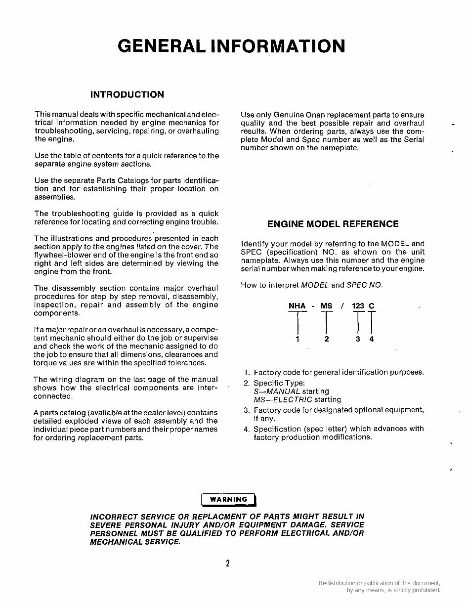
GENERAL INFORMATION INTRODUCTION This manual deals with specific mechanical and elec- trical information needed by engine mechanics for troubleshooting, servicing, repairing, or overhauling the engine. Use the table of contents for a quick reference to the separate engine system sections. Use the separate Parts Catalogs for parts identifica- tion and for establishing their proper location on assemblies. The troubleshooting guide is provided as a quick reference for locating and correcting engine trouble. The illustrations and procedures presented in each section apply to the engines listed on the cover. The flywheel-blower end of the engine is the front end so right and left sides are determined by viewing the engine from the front. The disassembly section contains major overhaul procedures for step by step removal, disassembly, inspection, repair and assembly of the engine components. If a major repair or an overhaul is necessary, a compe- tent mechanic should either do the job or supervise and check the work of the mechanic assigned to do the job to ensure that all dimensions, clearances and torque values are within the specified tolerances. The wiring diagram on the last page of the manual shows how the electrical components are inter- connected. A parts catalog (available at the dealer level) contains detailed exploded views of each assembly and the individual piece part numbers and their proper names for ordering replacement parts. Use only Genuine Onan replacement parts to ensure quality and the best possible repair and overhaul results. When ordering parts, always use the com- plete Model and Spec number as well as the Serial number shown on the nameplate. - ENGINE MODEL REFERENCE Identify your model by referring to the MODEL and SPEC (specification) NO. as shown on the unit nameplate. Always use this number and the engine serial number when making reference toyour engine. How to interpret MODEL and SPEC NO. NHA - MS / 123 C T T TT 1 2 3 4 1. Factory code for general identification purposes. 2. Specific Type: S-MANUAL starting MS-ELEC TRlC starting if any. factory production modifications. 3. Factory code for designated optional equipment, 4. Specification (spec letter) which advances with , WARNING I INCORRECT SERVICE OR REPLACMENT OF PARTS MIGHT RESULT IN SEVERE PERSONAL INJURY AND/OR EQUIPMENT DAMAGE. SERVICE PERSONNEL MUST BE QUALIFIED TO PERFORM ELECTRICAL AND/OR MECHANl CA L S ER VICE. 2
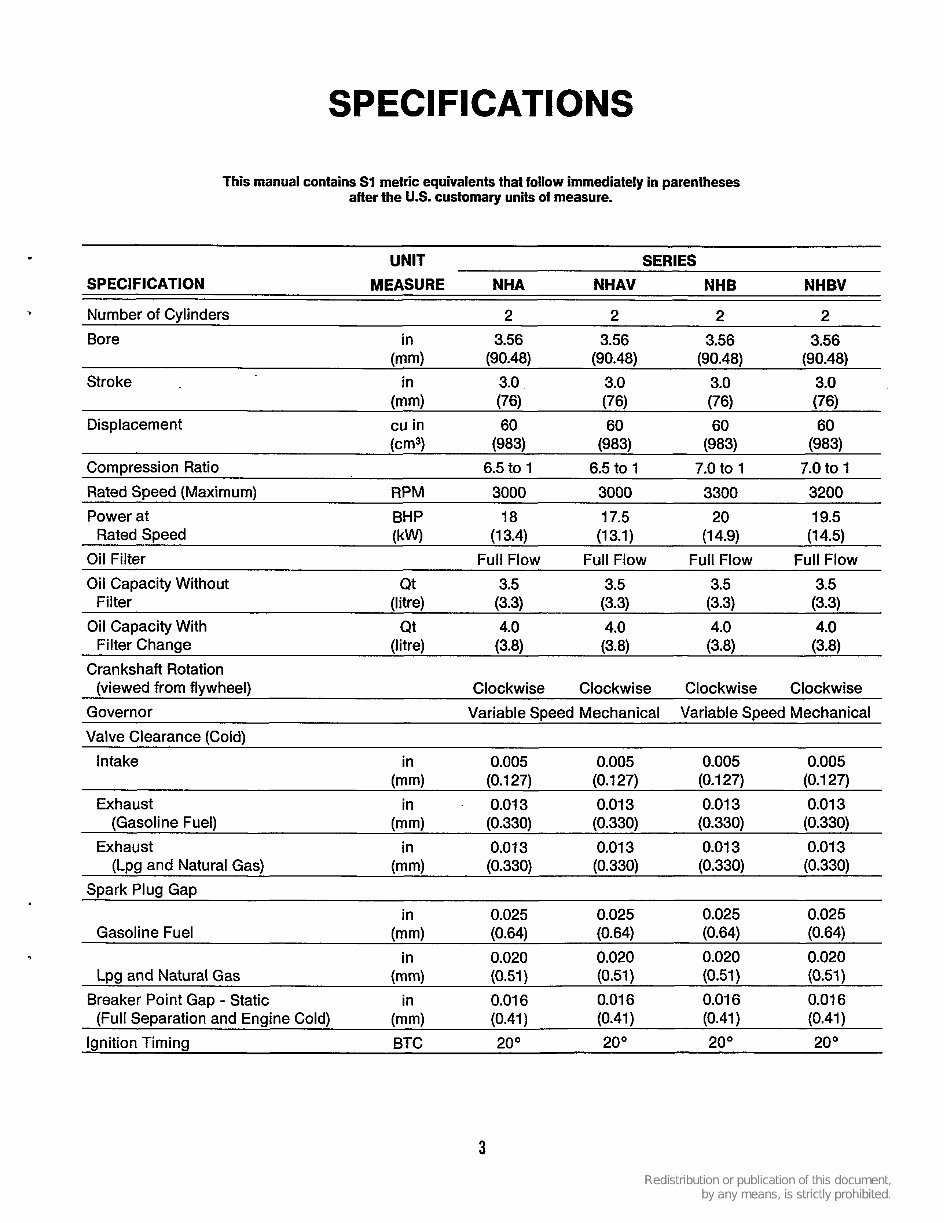
SPECIFICATIONS This manual contains Sl metric equivalents that follow immediately in parentheses after the U.S. customary units of measure. UNIT SERIES SPECIFICATION MEASURE NHA NHAV NHB NHBV Number of Cylinders 2 2 2 2 Bore in 3.56 3.56 3.56 3.56 Stroke in 3.0 3.0 3.0 3.0 Displacement cu in 60 60 60 60 Compression Ratio 6.5 to 1 6.5 to 1 7.0 to 1 7.0 to 1 Rated Speed (Maximum) RPM 3000 3000 3300 3200 (mm) (90.48) (90.48) (90.48) (90.48) (mm) (76) (76) (76) (76) @m3) (983) (983) (983) (983) Power at BHP 18 17.5 20 19.5 Oil Filter Full Flow Full Flow Full Flow Full Flow Rated Speed (kW) (1 3.4) (1 3.1) (1 4.9) (1 4.5) Oil Capacity Without Qt 3.5 3.5 3.5 3.5 Filter (litre) (3.3) (3.3) (3.3) (3-3) Oil Capacity With Qt 4.0 4.0 4.0 4.0 Filter Change (I i t re) (34 (3.8) (3.8) (3.8) Crankshaft Rotation (viewed from flywheel) Clockwise Clockwise Clockwise Clockwise Governor Variable SDeed Mechanical Variable SDeed Mechanical Valve Clearance (Cold) Intake in 0.005 0.005 0.005 0.005 (mm) (0.1 27) (0.1 27) (0.1 27) (0.1 27) Exhaust in 0.01 3 0.01 3 0.01 3 0.01 3 (Gasoline Fuel) (mm) (0.330) (0.330) (0.330) (0.330) Exhaust in 0.01 3 0.01 3 0.01 3 0.01 3 (Lpg and Natural Gas) (mm) (0.330) (0.330) (0.330) (0.330) Spark Plug Gap in 0.025 0.025 0.025 0.025 Gasoline Fuel (mm) (0.64) (0.64) (0.64) (0.64) in 0.020 0.020 0.020 0.020 Lpg and Natural Gas (mm) (0.51) (0.51) (0.51) (0.51) Breaker Point Gap - Static in 0.01 6 0.01 6 0.01 6 0.01 6 (Full Separation and Engine Cold) (mm) (0.41) (0.41) (0.41) (0.41) Ignition Timing BTC 20° 20" 20 " 20" 3
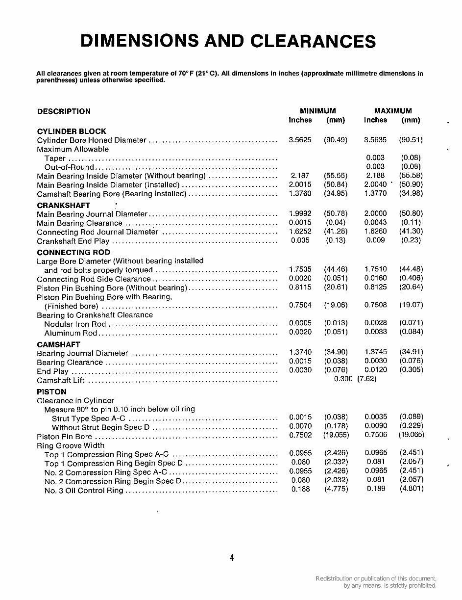
DIMENSIONS AND CLEARANCES All clearances given at room temperature of 70" F (21OC) . All dimensions in inches (approximate millimetre dimensions in parentheses) unless otherwise specified . DESCRIPTION CYLINDER BLOCK Maximum Allowable Cylinder Bore Honed Diameter ....................................... Taper ............................................................... Out-of-Round ....................................................... Main Bearing Inside Diameter (Without bearing) ..................... Main Bearing Inside Diameter (Installed) ............................. CRANKSHAFT Camshaft Bearing Bore (Bearing installed) ........................... Main Bearing Journal Diameter ....................................... Main Bearing Clearance .............................................. Connecting Rod Journal Diameter ................................... Crankshaft End Play .................................................. CONNECTING ROD Large Bore Diameter (Without bearing installed and rod bolts properly torqued ..................................... Connecting Rod Side Clearance ...................................... Piston Pin Bushing Bore (Without bearing) ........................... (Finished bore) ..................................................... Nodular Iron Rod ................................................... Aluminum Rod ...................................................... Bearing Journal Diameter ............................................ Bearing Clearance .................................................... End Play .............................................................. Camshaft Lift ......................................................... PISTON Clearance in Cylinder Piston Pin Bushing Bore with Bearing. Bearing to Crankshaft Clearance CAMSHAFT Measure 90" to pin 0.10 inch below oil ring Strut Type Spec A-C ............................................. Without Strut Begin Spec D ...................................... Piston Pin Bore ....................................................... Ring Groove Width Top 1 Compression Ring Spec A-C ................................ Top 1 Compression Ring Begin Spec D ............................ No. 2 Compression Ring Spec A-C ................................. No . 2 Compression Ring Begin Spec D ............................. No . 3 Oil Control Ring .............................................. MINIMUM MAXIMUM Inches (mm) Inches (mm) 3.5625 (90.49) 3.5635 (90.51) 0.003 (0.08) 0.003 (0.08) 2.187 (55.55) 2.188 (55.58) 2.0015 (50.84) 2.0040 (50.90) 1.3760 (34.95) 1.3770 (34.98) 1.9992 (50.78) 2.0000 (50.80) 0.0015 (0.04) 0.0043 (0.11) 1.6252 (41.28) 1.6260 (41.30) 0.005 (0.13) 0.009 (0.23) 1.7505 (44.46) 1.7510 (44.48) 0.0020 (0.051 ) 0.0160 (0.406) 0.8115 (20.61) 0.8125 (20.64) 0.7504 (1 9.06) 0.7508 (1 9.07) 0.0005 (0.013) 0.0028 (0.071) 0.0020 (0.051) 0.0033 (0.084) 1.3740 (34.90) 1.3745 (34.91) 0.0015 (0.038) 0.0030 (0.076) 0.0030 (0.076) 0.0120 (0.305) 0.300 (7.62) 0.0015 (0.038) 0.0035 (0.089) 0.0070 (0.178) 0.0090 (0.229) 0.7502 (19.055) 0.7506 (19.065) 0.0955 (2.426) 0.0965 (2.451) 0.080 (2.032) 0.081 (2.057) c 0.0955 (2.426) 0.0965 (2.451) 0.080 (2.032) 0.081 (2.057) 0.188 (4.775) 0.189 (4.801) 4
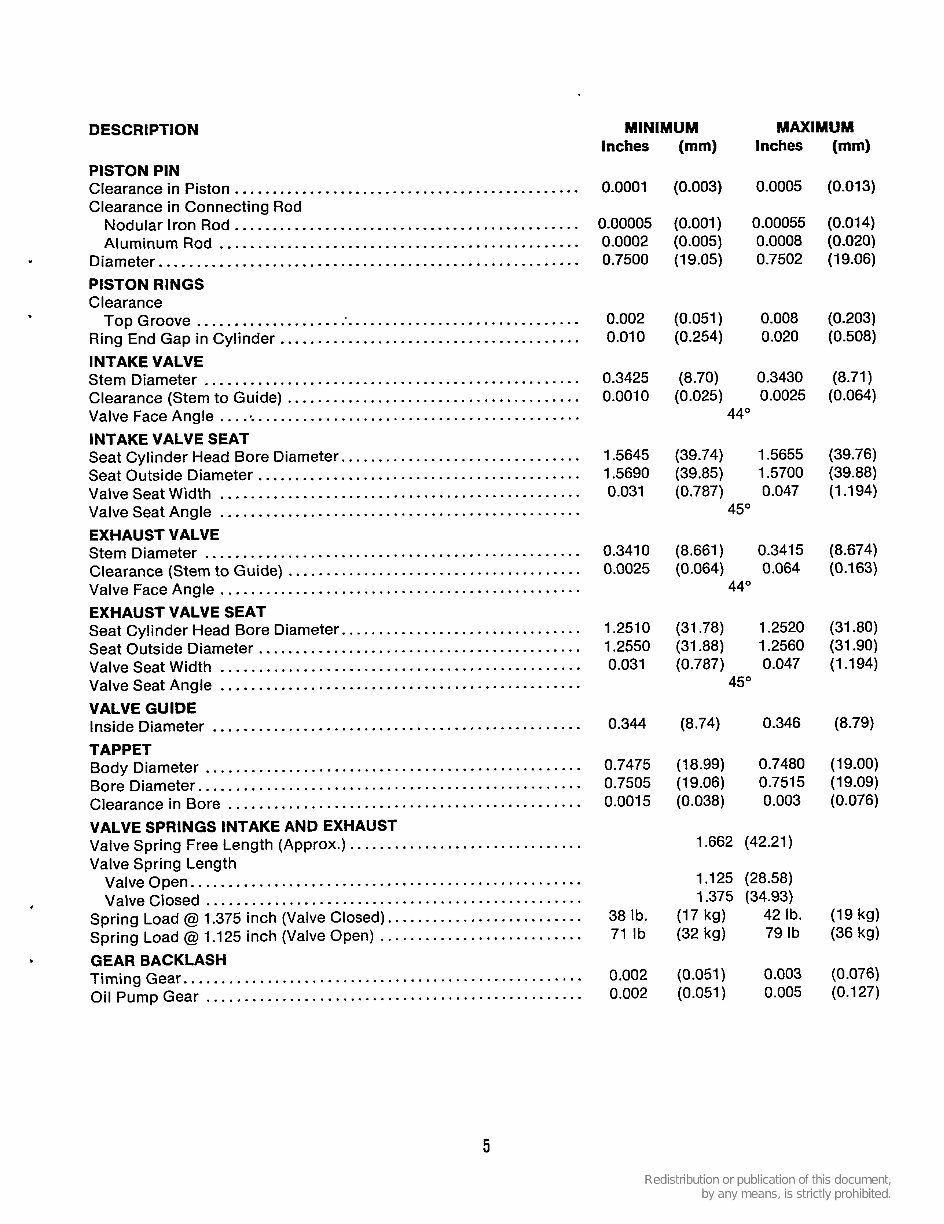
DESCRIPTION MINIMUM MAXIMUM Inches (mm) Inches (mm) PISTON PIN Clearance in Piston .............................................. Clearance in Connecting Rod Nodular Iron Rod .............................................. Aluminum Rod ................................................ Diameter ........................................................ PISTON RINGS Clearance Top Groove .................................................... Ring End Gap in Cylinder ........................................ INTAKE VALVE Stem Diameter .................................................. Clearance (Stem to Guide) ....................................... Valve Face Angle ................................................. INTAKE VALVE SEAT Seat Cylinder Head Bore Diameter ................................ Seat Outside Diameter ........................................... Valve Seat Width ................................................ Valve Seat Angle ................................................ EXHAUST VALVE Stem Diameter .................................................. Clearance (Stem to Guide) ....................................... Valve Face Angle ................................................ EXHAUST VALVE SEAT Seat Cylinder Head Bore Diameter ................................ Seat Outside Diameter ........................................... Valve Seat Width ................................................ Valve Seat Angle ................................................ VALVE GUIDE Inside Diameter ................................................. TAPPET Body Diameter .................................................. Bore Diameter ................................................... Clearance in Bore ............................................... VALVE SPRINGS INTAKE AND EXHAUST Valve Spring Length Valve Spring Free Length (Approx.) ............................... Valve Open .................................................... Spring Load @ 1.375 inch (Valve Closed) .......................... Spring Load @ 1.125 inch (Valve Open) ........................... Timing Gear ..................................................... Oil Pump Gear .................................................. Valve Closed .................................................. GEAR BACKLASH 0.0001 (0.003) 0.0005 (0.013) 0.00005 (0.001) 0.00055 (0.014) 0.0002 (0.005) 0.0008 (0.020) 0.7500 (1 9.05) 0.7502 (1 9.06) 0.002 (0.051) 0.008 (0.203) 0.010 (0.254) 0.020 (0.508) 0.3425 (8.70) 0.3430 (8.71) 0.001 0 (0.025) 0.0025 (0.064) 44" 1.5645 (39.74) 1 S655 (39.76) 1.5690 (39.85) 1.5700 (39.88) 0.031 (0.787) 0.047 (1.194) 45" 0.3410 (8.661 ) 0.3415 (8.674) 0.0025 (0.064) 0.064 (0.163) 44" 1.251 0 (31.78) 1.2520 (31-80) 1.2550 (31.88) 1.2560 (31.90) 0.031 (0.787) 0.047 (1.194) 45" 0.344 (8.74) 0.346 (8.79) 0.7475 (1 8.99) 0.7480 (1 9.00) 0.7505 (19.06) 0.751 5 (1 9-09) 0.001 5 (0.038) 0.003 (0.076) 1.662 (42.21) 1.125 (28.58) 38 Ib . (17 kg) 42 Ib . (19 kg) 71 Ib (32 kg) 79Ib (36 kg) 1.375 (34.93) 0.002 (0.051) 0.003 (0.076) 0.002 (0.051) 0.005 (0.127) 5
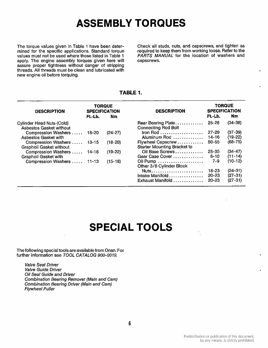
ASSEMBLY TORQUES The torque values given in Table 1 have been deter- mined for the specific applications. Standard torque values must not be used where those listed in Table 1 apply. The engine assembly torques given here will assure proper tightness without danger of stripping threads. All threads must be clean and lubricated with new engine oil before torquing. Check all studs, nuts, and capscrews, and tighten as required to keep them from working loose. Refer to the PARTS MANUAL for the location of washers and capscrews. TABLE 1. DESCRIPTION Cylinder Head Nuts (Cold) Asbestos Gasket without Asbestos Gasket with Graphoil Gasket without Graphoil Gasket with Compression Washers ..... Compression Washers ..... Compression Washers ..... Compression Washers ..... TORQUE SPECIFICATION DESCRIPTION Ft.-Lb. Nm Rear Bearing Plate.. ........... Iron Rod.. .................. Aluminum Rod .............. 13-1 5 (1 8-20) Flywheel Capscrew ............ Starter Mounting Bracket to 14-16 (1 9-22) Oil Base Screws.. ........... Gear Case Cover.. ............ 11-13 (15-18) Oil Pump ..................... Other 3/8 Cylinder Block Nuts, ....................... Intake Manifold.. .............. Exhaust Manifold .............. Connecting Rod Bolt '1 8-20 (24-27) SPECIAL TOOLS The following special tools are available from Onan. For further information see TOOL CATALOG 900-0079. Valve Seat Driver Valve Guide Driver Oil Seal Guide and Driver Combination Bearing Remover (Main and Cam) Combination Bearing Driver (Main and Cam) Flywheel Puller TORQUE SPECIFICATION Ft.-Lb. Nm 25-28 (34-38) 27-29 (37-39) 14-1 6 (1 9-22) 50-55 (68-75) 25-35 (34-47) 8-10 (11-14) 7-9 (10-12) 18-23 (24-31) 20-23 (27-31) 20-23 (27-31) 6
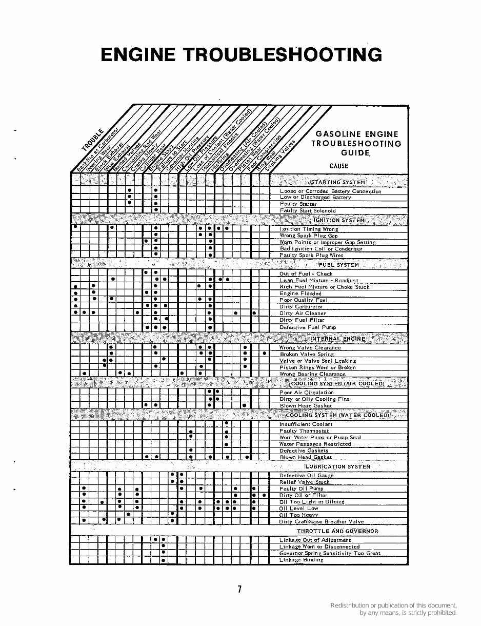
ENGINE TROUBLESHOOTING GASOLINE ENGINE TR OU BLES H 0 OTlN G t . . . - . . i - . . . - . _ . _ . . . A . - THROTTLE AND GOVERNOR 7
You're Reading a Preview
What's Included?
Lifetime Access
Fast Download Speeds
Online & Offline Access
Access PDF Contents & Bookmarks
Full Search Facility
Print one or all pages of your manual
$39.99
Onan Cummins NHA, NHAV, NHB & NHBV Engine Service & Parts Manual -