

Onan Marine MDL3 MDL4 MDL6 Service Manual 934-0500
What's Included?
Fast Download Speeds
Online & Offline Access
Access PDF Contents & Bookmarks
Full Search Facility
Print one or all pages of your manual

Caution: This document contains mixed page sizes (8.5 x 11 or 11 x
17), which may affect printing. Please adjust your printer settings
according to the size of each page you wish to print.
MDL3
MDL4
MDL6
.s
1
, ~-
I
934-0500
. 8-91
Printed in U.S.A.
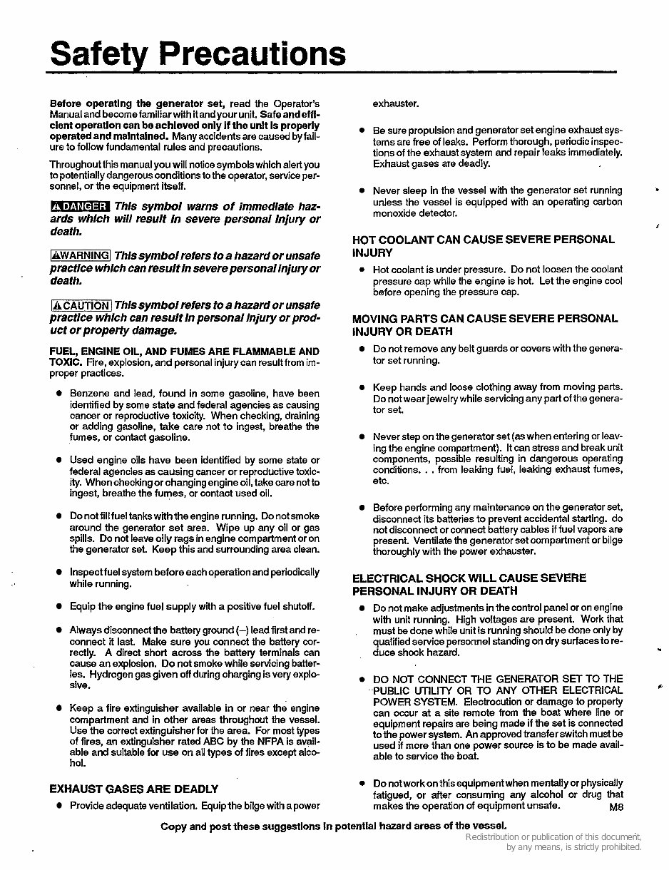
Safety Precautions
Before operating the generator set, read the Operator’s
Manualandbecomefamiliarwith it andvourunit. Safeandeffl-
exhauster.
dent operatlon can be achleved onli if the unit is properly
operated and maintained. Manyaccidents are caused byfail-
ure to follow fundamental rules and precautions.
Throughout this manualyou will notice symbolswhich alert you
to potentiallydangerousconditionsto the operator, service per-
sonnel, or the equipment itself.
. D’ This symbol warns of immedlate haz-
ards which will result in severe personal Injury or
death.
1 - 1 Thissymbol refers to a hazard or unsafe
practlce which can result in severe personal injury or
death.
[A CAUTiON 1 Thls symbol mfers to a hazard or unsafe
practlce which can result in personal Injury or prod-
uct or properfy damage.
FUEL, ENGINE OIL, AND FUMES ARE FLAMMABLE AND
TOXIC. Fire, explosion, and personalinjurycan result from im-
proper practices.
Benzene and lead, found in some gasoline, have been
identifiedby some state and federal agencies as causing
cancer or reproductive toxicity. When checking, draining
or adding gasoline, take care not to ingest, breathe the
fumes, or contact gasoline.
Used engine oils have been identified by some state or
federal agencies as causingcancer or reproductive toxic-
ity. Whencheckingor changingengineoil, take care notto
ingest, breathe the fumes, or contact used oil.
Do not fill fueltankswith the engine running. Do notsmoke
around the generator set area. Wipe up any oil or gas
spills. Do not leaveoily rags in engine compartment or on
the generator set. Keep this and surrounding area clean.
lnspectfuel system beforeeachoperationand periodically
while running.
Equip the engine fuel supply with a positive fuel shutoff.
Always disconnectthe battery ground (-) leadfirst and re-
connect it last. Make sure you connect the battery cor-
rectly. A direct short across the battery terminals can
cause an explosion. Do not smoke while servicing batter-
ies. Hydrogen gas given off during charging is very explo-
sive.
0 Be sure propulsionand generator set engine exhaust sys-
tems are free of leaks. Performthorough, periodic inspec-
tions of the exhaust system and repair leaks immediately.
Exhaust gases are deadly.
0 Never sleep in the vessel with the generator set running
unless the vessel is equipped with an operating carbon
monoxide detector.
.
3
HOT COOLANT CAN CAUSE SEVERE PERSONAL
INJURY
0 Hot coolant is under pressure. Do not loosen the coolant
pressure cap while the engine is hot. Let the engine cool
before opening the pressure cap.
MOVING PARTS CAN CAUSE SEVERE PERSONAL
INJURY OR DEATH
Do not removeany belt guards or covers with the genera-
tor set running.
Keep hands and loose clothing away from moving parts.
Do notwearjewelry while servicingany part of the genera-
tor set.
Never step on the generator set (as when entering or leav-
ingthe engine compartment). It can stress and break unit
components, possible resulting in dangerous operating
conditions. . . from leaking fuel, leaking exhaust fumes,
etc.
Beforeperformingany maintenance on the generator set,
disconnect its batteries to prevent accidental starting. do
not disconnect or connect battery cables if fuel vapors are
present. Ventilate the generatorset compartment or bilge
thoroughly with the power exhauster.
ELECTRICAL SHOCK WILL CAUSE SEVERE
PERSONAL INJURY OR DEATH
Do not make adjustmentsinthe control panel or on engine
with unit running. High voltages are present. Work that
must be done while unit is runningshould be done only by
qualified service personnelstandingon dry surfacesto re-
duce shock hazard.
.
U
0 DO NOT CONNECT THE GENERATOR SET TO THE
PUBLIC UTILITY OR TO ANY OTHER ELECTRICAL
P
POWER SYSTEM. Electrocution or damage to property
can occur at a site remote from the boat where line or
equipment repairs are being made if the set is connected
to the power system. An approvedtransfer switch must be
used if more than one power source is to be made avail-
able to service the boat.
Keep a fire extinguisher available in or near the engine
compartment and in other areas throughout the vessel.
Use the correct extinguisher for the area. For most types
of fires, an extinguisher rated ABC by the NFPA is avail-
able and suitable for use on all types of fires except alco-
hol.
0 Do notworkon this equipment when mentallyor physically
fatigued, or after consuming any alcohol or drug that
makes the operation of equipmentunsafe. M8
EXHAUST GASES ARE DEADLY
Provideadequate ventilation. Equip the bilgewith a power
Copy and post these suggestions In potential hazard areas of the vessel.
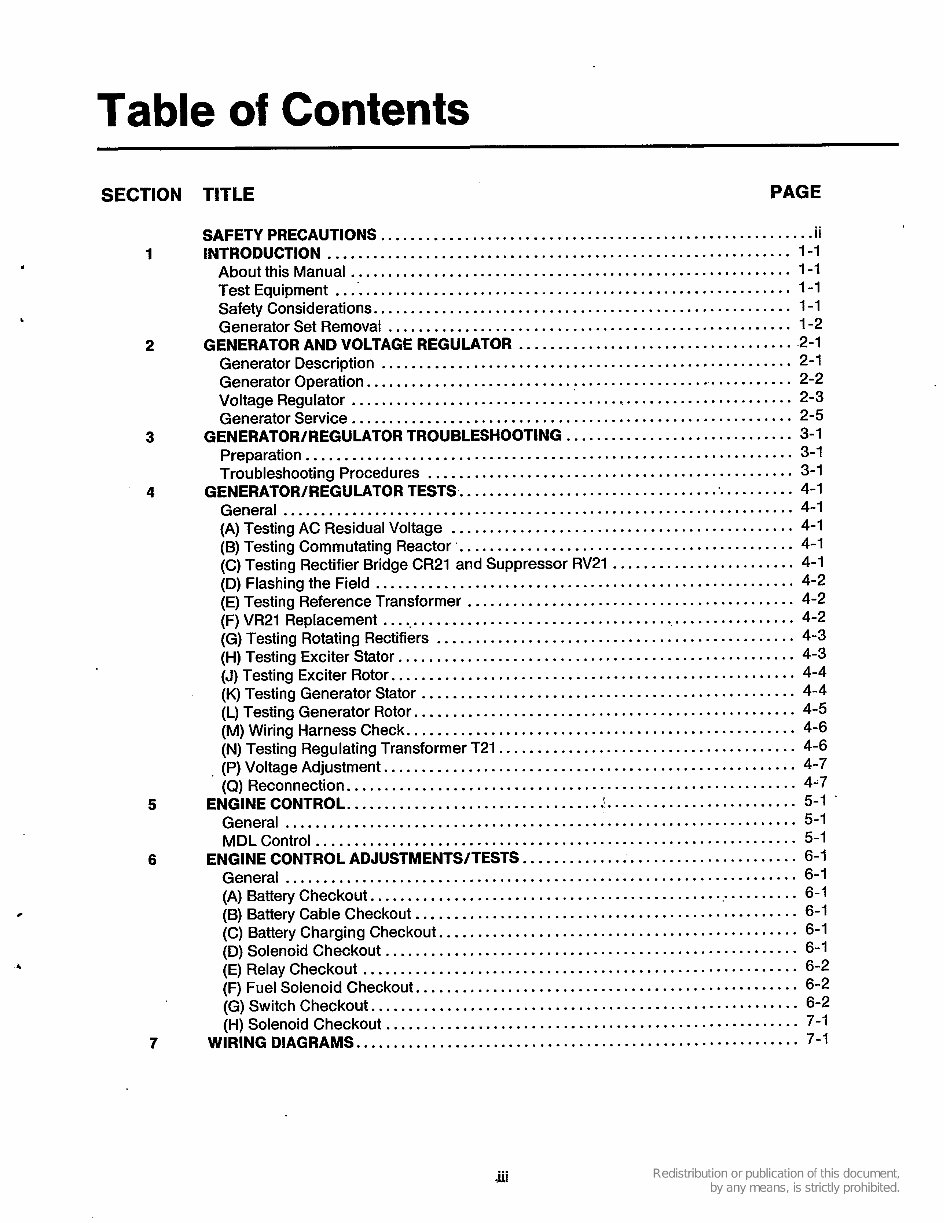
Table of Contents
SECTION TITLE PAGE
SAFETY PRECAUTIONS ......................................................... ii
1 INTRODUCTION ............................................................. 1-1
About this Manual .......................................................... 1-1
Test Equipment ............................................................. 1-1
Safety Considerations ....................................................... 1-1
Generator Set Removal ..................................................... 1-2
GENERATOR AND VOLTAGE REGULATOR ..................................... 2-1
Generator Description ...................................................... 2-1
Generator Operation ........................................................ 2-2
Voltage Regulator ........................................................... 2-3
Generator Service .......................................................... 2-5
3 GENERATOWREGULATOR TROUBLESHOOTING .............................. 3-1
Preparation ................................................................ 3-1
Troubleshooting Procedures ................................................ 3-1
4 GENERATOWREGULATOR TESTS .............................................. 4-1
General ................................................................... 4-1
(A) Testing AC Residual Voltage ............................................. 4-1
(B) Testing Commutating Reactor ............................................. 4-1
(C) Testing Rectifier Bridge CR21 and Suppressor RV21 ........................ 4-1
(D) Flashing the Field ....................................................... 4-2
(E) Testing Reference Transformer ........................................... 4-2
(F) VR21 Replacement ....................................................... 4-2
(G) Testing Rotating Rectifiers ............................................... 4-3
(H) Testing Exciter Stator .................................................... 4-3
(J) Testing Exciter Rotor ..................................................... 4-4
(K) Testing Generator Stator ................................................. 4-4
(L) Testing Generator Rotor .................................................. 4-5
(M) Wiring Harness Check ................................................... 4-6
(N) Testing Regulating Transformer T21 ....................................... 4-6
. (P) Voltage Adjustment ...................................................... 4-7
(Q) Reconnection ........................................................... 4-7
General ................................................................... 5-1
MDL Control ............................................................... 5-1
ENGINE CONTROL ADJUSTMENTS/TESTS .................................... 6-1
General ................................................................... 6-1
(A) Battery Checkout ......................................................... 6-1
(B) Battery Cable Checkout .................................................. 6-1
(C) Battery Charging Checkout ............................................... 6-1
(D) Solenoid Checkout ...................................................... 6-1
(E) Relay Checkout ......................................................... 6-2
(F) Fuel Solenoid Checkout .................................................. 6-2
(G) Switch Checkout ........................................................ 6-2
(H) Solenoid Checkout ...................................................... 7-1
7 WIRING DIAGRAMS .......................................................... 7-1
2
5 ENGINE CONTROL ................................. ......................... 5-1 .
6
. iii

I
Section 1 Introduction
ABOUT THIS MANUAL
This manual covers troubleshooting and repair informa-
tion for the generator and control. Refer to a separate
engine service manual 934-0750 when servicing the
engine.
This manual has separate sections for the generator
and voltage regulator, engine control, and associated
wiring diagrams. While the wiring diagrams at the end of
the manual are included to help trace or isolate prob-
lems, it is suggested that service personnel use the
wiring diagrams shipped with the unit for trouble-
shooting.
Repair information for solid state printed circuit boards
is not extensive because they lend themselves more to
replacement than repair. Application of meters or hot
soldering irons to printed circuit boards by other than
qualified personnel can cause unnecessary and expen-
sive damage.
Repair of the printed circuit boards is not recommended
except by the factory. A return and exchange service
has been initiated whereby faulty printed circuit boards
can be returned to the Distributor and exchanged for
good units. For more information, contact your Onan
Distributor.
b
High voltage (Megger) testing or high
1 - 1 potential (high pot) testing oigenera-
tor windings can cause damage to solid state compo-
nents. Isolate these components before testing.
TEST EQUIPMENT
Most of the test procedures in this manual can be per-
formed'with an AC-DC multimeter such as a Simpson
Model 260 VOM or a digital VOM. Some other instru-
ments to have available are:
0 Megger or Insulation Resistance Meter
0 Onan Multitester
0 Wheatstone Bridge
0 Jumper Leads
0 Load Test Panel
0 Variac
0 AC Voltmeter
DC Voltmeter
Frequency Meter
Tachometer or Strobotach
See Tool Catalog 900-001 9.
Several troubleshooting guides are included in this
manual to help the serviceperson locate the cause of
various malfunctions. Note that some malfunctions
might have several possible'causes. For this reason,the
service person may haveto investigate several problem
areas in order to isolate the source of the malfunction.
Because of the complexity of the product, a trouble-
shooting chart cannot list every malfunction and cause.
In some situations, the serviceperson will haveto rely on
experience and a knowledge of the product to locate the
problem and service as required.
SAFETY CONSIDERATIONS
Always consider the safety aspects of any service
procedure. Generator sets present several hazards that
the serviceperson must be aware of to safely complete
the job. Read through the safety precautions listed on
the inside cover and familiarize yourself with the various
hazards shown in Table 1-1. Once the hazards are
known, approach the job with a safety conscious atti-
tude. Being safety conscious is the most effective way to
avoid injury to yourself or others. Reduce the chance
that an accident will occur by adopting the following
safeguards.
Safeguards to Avoid Hazards
0 Use Personal Protection - Protect your body by
wearing appropriate safety equipment. Protective
clothing includes safety shoes, gloves, safety
glasses, and hard hats. Leave rings and jewelry off
and do not wear loose clothing that might get
caught on equipment.
0 Work to Reduce the Hazard - The, workshop area
and all pieces of equipment used can contribute to
reducing the hazard potential. Keep guards and
shields in place on machinery and maintain equip-
ment in good working condition. Store flammable
liquids in approved containers, or other ignition
source. Keep the workshop clean and well-lighted,
and provide adequate ventilation. Keep fire extin-
guishers and safety equipment nearby and be pre-
pared to respond to an emergency.
1-1
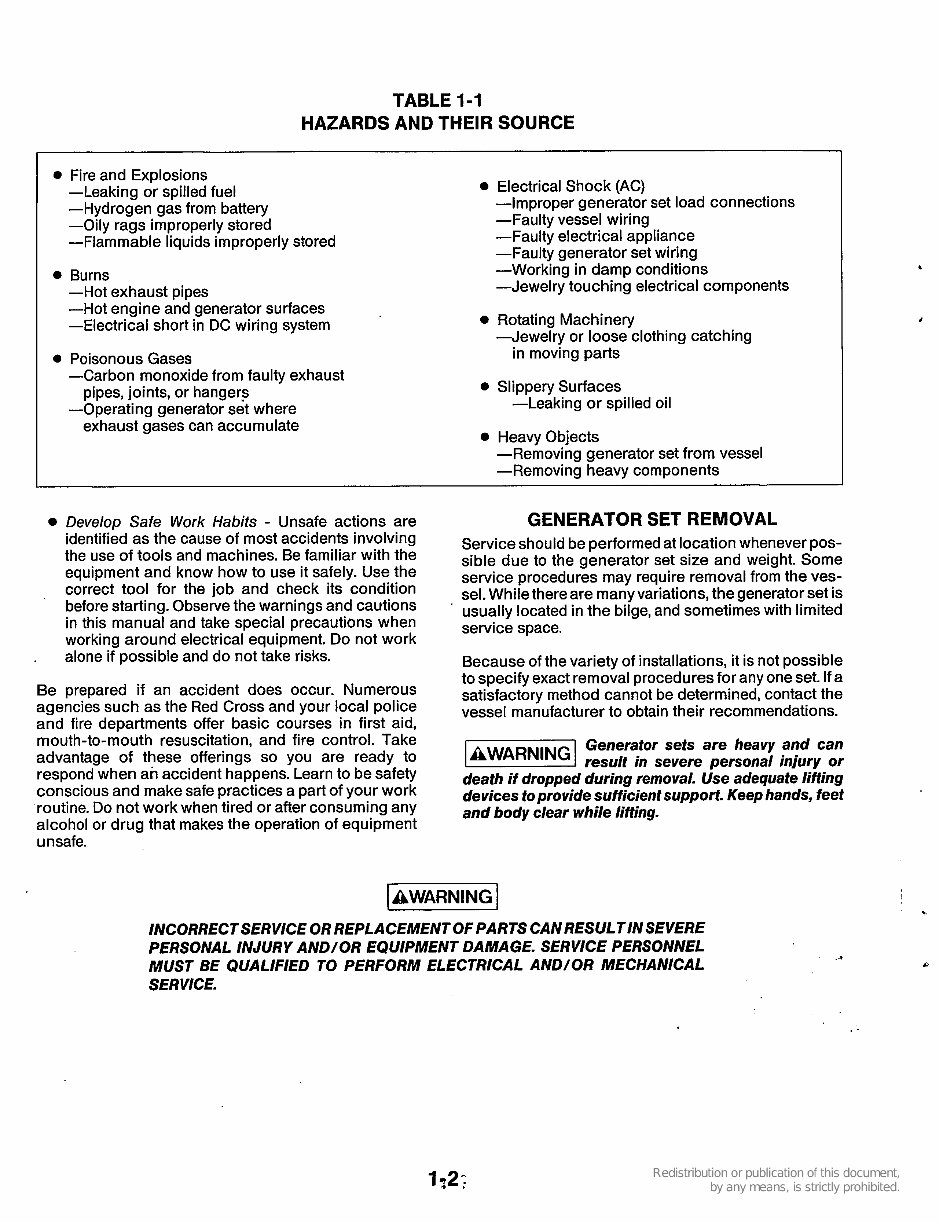
TABLE 1-1
HAZARDS AND THEIR SOURCE
0 Fire and Explosions
-Leaking or spilled fuel
-Hydrogen gas from battery
-Oily rags improperly stored
-Flammable liquids improperly stored
0 Burns
-Hot exhaust pipes
-Hot engine and generator surfaces
-Electrical short in DC wiring system
-Carbon monoxide from faulty exhaust
pipes, joints, or hangers
-Operating generator set where
exhaust gases can accumulate
0 Poisonous Gases
0 Electrical Shock (AC)
-Improper generator set load connections
-Faulty vessel wiring
-Faulty electrical appliance
-Faulty generator set wiring
-Working in damp conditions
-Jewelry touching electrical components
0 Rotating Machinery
-Jewelry or loose clothing catching
in moving parts
0 Slippery Surfaces
-Leaking or spilled oil
0 Heavy Objects
-Removing generator set from vessel
-Removing heavy components
0 Develop Safe Work Habits - Unsafe actions are GENERATOR SET REMOVAL
identified as the cause of most accidents involving
the use of tools and machines. Be familiar with the
equipment and know how to use it safely. Use the
correct tool for the job and check its condition
before starting. Observe the warnings and cautions
in this manual and take special precautions when
working around electrical equipment. Do not work
alone if possible and do not take risks.
Be prepared if an accident does occur. Numerous
agencies such as the Red Cross and your local police
and fire departments offer basic courses in first aid,
mouth-to-mouth resuscitation, and fire control. Take
advantage of these offerings so you are ready to
respond when an accident happens. Learn to be safety
conscious and make safe practices a part of your work
routine. Do not work when tired or after consuming any
alcohol or drug that makes the operation of equipment
unsafe.
Service should be performed at location whenever pos-
sible due to the generator set size and weight. Some
service procedures may require removal from the ves-
sel. While there are many variations, the generator set is
usually located in the bilge, and sometimes with limited
service space.
Because of the variety of installations, it is not possible
to specify exact removal proceduresfor any one set. If a
satisfactory method cannot be determined, contact the
vessel manufacturer to obtain their recommendations.
Generator sets are heavy and can
l3!ZEEI result in severe personal injury or
death if dropped during removal. Use adequate lifting
devices to provide sufficient support. Keep hands, feet
and body clear while lifting.
IAWARNING I
INCORRECTSERVICE OR REPLACEMENTOF PARTSCANRESULTINSEVERE
PERSONAL INJURY AND/OR EQUIPMENT DAMAGE. SERVICE PERSONNEL
MUST BE QUALIFIED TO PERFORM ELECTRICAL AND/OR MECHANICAL
SERVICE.
P
..
Section 2. Generator/Voltage Regulator
GENERATOR DESCRIPTION
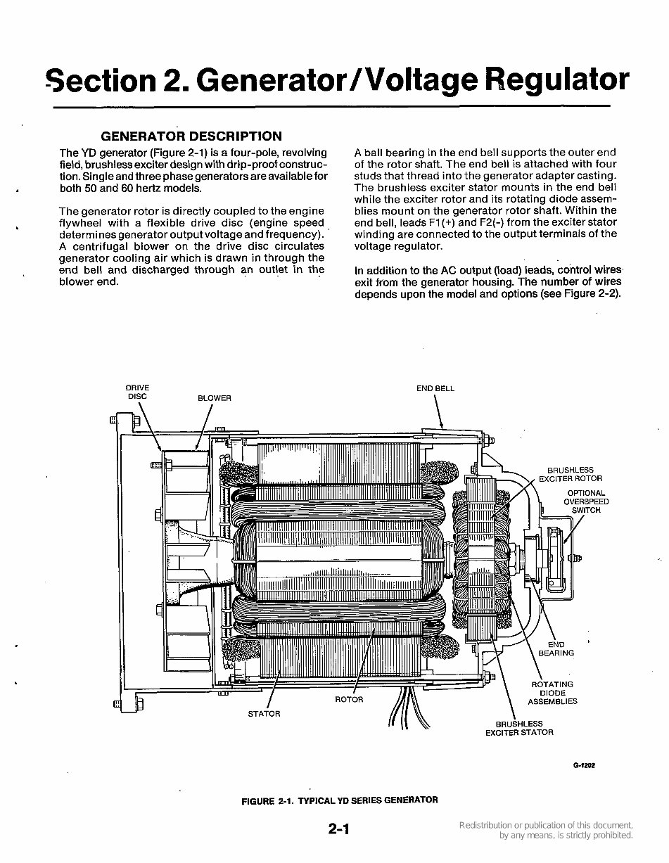
The YD generator (Figure 2-1) is a four-pole, revolving
field, brushless exciter design with drip-proof construc-
tion. Single and three phase generators are available for
both 50 and 60 hertz models. d
The generator rotor is directly coupled to the engine
flywheel with a flexible drive disc (engine speed
determines generator output voltage and frequency).
A centrifugal blower on the drive disc circulates
generator cooling air which is drawn in through the
end bell and discharged through an outlet in the
blower end.
.
DRIVE
DISC BLOWER
A ball bearing in the end bell supports the outer end
of the rotor shaft. The end bell is attached with four
studs that thread into the generator adapter casting.
The brushless exciter stator mounts in the end bell
while the exciter rotor and its rotating diode assem-
blies mount on the generator rotor shaft. Within the
end bell, leads F1 (+) and F2(-) from the exciter stator
winding are connected to the output terminals of the
voltage regulator.
In addition to the AC output (load) leads, control wires.
exit ffom the generator housing. The number of wires
depends upon the model and options (see Figure 2-2).
END BELL
\
FIGURE 2-1. TYPICAL YD SERIES GENERATOR
2-1
CONTROL LEADS
THREE-PHASE
ll
CODE
3 8 53
SINGLE
PHASE
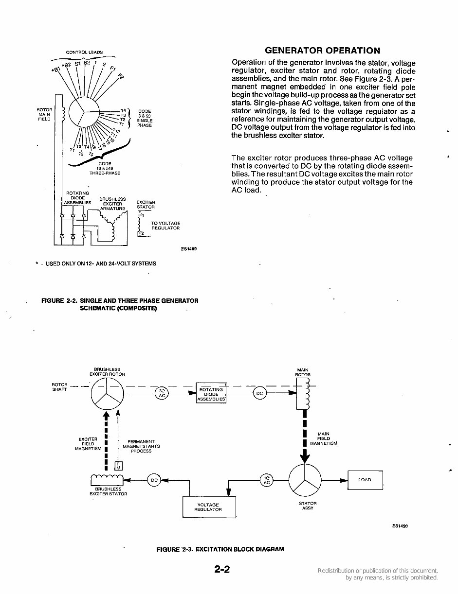
GENERATOR OPERATION
Operation of the generator involves the stator, voltage
regulator, exciter stator and rotor, rotating diode
assemblies, and the main rotor. See Figure 2-3. A per-
manent magnet embedded in one exciter field pole
begin the voltage build-up process as the generator set
starts. Single-phase AC voltage, taken from one of the
stator windings, is fed to the voltage regulator as a
reference for maintaining the generator output voltage.
DC voltage output from the voltage regulator is fed into
the brushless exciter stator.
b
The exciter rotor produces three-phase AC voltage
that is converted to DC by the rotating diode assem-
blies. The resultant DC voltage excites the main rotor
winding to produce the stator output voltage for the
AC load.
1
EXCITER
STATOR
ES1489
* - USED ONLY ON 12- AND 24-VOLT SYSTEMS
, FIGURE 2-2. SINGLE AND THREE PHASE GENERATOR
SCHEMATLC (COMPOSITE)
ROTOR
SHAFT
BRUSHLESS MAIN
EXCITER ROTOR ROTOR
- - . @+ -
ASSEMBLIES
W
?!
U
I
I
I'
EXCITER ' ' 1 : :
I I PERMANENT I MAGNETISM
MAGNETISM I I MA$~~c~sRTs
BRUSHLESS
EXCITER STATOR
I
STATOR
ASSY
VOLTAGE
I REGULATOR
1
ES1490
FIGURE '2-3. EXCITATION BLOCK DIAGRAM
2-2
VOLTAGE REGULATOR
The voltage regulator controls the output of the
generator's0 that a constant voltage is maintained
under varying load conditions. There are two types of
voltage regulators used on these sets-transformer
and electronic (solid state). The description and
operation of each type is covered separately.
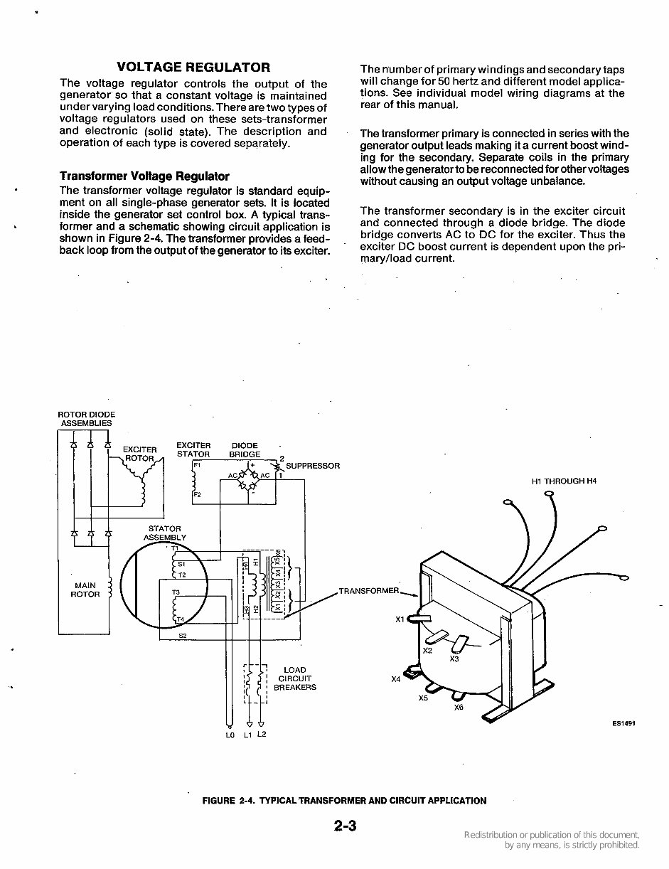
Transformer Voltage Regulator
The transformer voltage regulator is standard equip-
ment on all single-phase generator sets. It is located
inside the generator set control box. A typical trans-
shown in Figure 2-4. The transformer provides a feed-
back loop from the output of the generator to its exciter.
.
former and a schematic showing circuit application is
The number of primary windings and secondary taps
will change for 50 hertz and different model applica-
tions. See individual model wiring diagrams at the
rear of this manual.
The transformer primary is connected in series with the
generator output leads making it a current boost wind-
ing for the secondary. Separate coils in the primary
allow the generator to be reconnectedfor other voltages
without causing an output voltage unbalance.
The transformer secondary is in the exciter circuit
and connected through a diode bridge. The diode
bridge converts AC to DC for the exciter. Thus the
exciter DC boost current is dependent upon the pri-
mary/load current.
ROTOR DIODE
ASSEMBLIES
H1 THROUGH H4
ES1491
LO L1 L2
FIGURE 2-4. TYPICAL TRANSFORMER AND CIRCUIT APPLICATION
2-3
You're Reading a Preview
What's Included?
Fast Download Speeds
Online & Offline Access
Access PDF Contents & Bookmarks
Full Search Facility
Print one or all pages of your manual
$31.99
Viewed 21 Times Today


Secure transaction
What's Included?
Fast Download Speeds
Online & Offline Access
Access PDF Contents & Bookmarks
Full Search Facility
Print one or all pages of your manual
$31.99
Complete Factory Service Repair Workshop Manual is available for instant access on your computer, tablet, or smartphone. This Professional Manual covers all repairs, servicing, and troubleshooting procedures. It contains detailed pages with photos and diagrams, along with step-by-step instructions and highly detailed exploded diagrams and pictures. This manual is useful for both professional Mechanics and Technicians, as well as DIY enthusiasts. The files are easy to read, bookmarked, searchable, and can be viewed on almost any computer. You can print one page or the whole manual for your convenience.


