MS-1 iii Safety Precautions Before operating the generator set (genset), read the Operator’s Manual and become familiar with it and the equipment. Safe and efficient operation can be achieved only if the equipment is properly operated and maintained. Many accidents are caused by failure to follow fundamental rules and precautions. The following symbols, found throughout this manual, alert you to potentially dangerous conditions to the oper- ator, service personnel, or the equipment. This symbol warns of immediate hazards which will result in severe personal in- jury or death. WARNING This symbol refers to a hazard or un- safe practice which can result in severe person- al injury or death. CAUTION This symbol refers to a hazard or un- safe practice which can result in personal injury or product or property damage. FUEL AND FUMES ARE FLAMMABLE Fire, explosion, and personal injury or death can result from improper practices. • DO NOT fill fuel tanks while engine is running, un- less tanks are outside the engine compartment. Fuel contact with hot engine or exhaust is a potential fire hazard. • DO NOT permit any flame, cigarette, pilot light, spark, arcing equipment, or other ignition source near the generator set or fuel tank. • Fuel lines must be adequately secured and free of leaks. Fuel connection at the engine should be made with an approved flexible line. Do not use copper piping on flexible lines as copper will be- come brittle if continuously vibrated or repeatedly bent. • Natural gas is lighter than air, and will tend to gather under hoods. Propane is heavier than air, and will tend to gather in sumps or low areas. NFPA code re- quires all persons handling propane to be trained and qualified. • Be sure all fuel supplies have a positive shutoff valve. • Be sure battery area has been well-ventilated prior to servicing near it. Lead-acid batteries emit a highly explosive hydrogen gas that can be ignited by arc- ing, sparking, smoking, etc. EXHAUST GASES ARE DEADLY • Provide an adequate exhaust system to properly expel discharged gases away from enclosed or sheltered areas and areas where individuals are likely to congregate. Visually and audibly inspect the exhaust daily for leaks per the maintenance schedule. Make sure that exhaust manifolds are se- cured and not warped. Do not use exhaust gases to heat a compartment. • Be sure the unit is well ventilated. • Engine exhaust and some of its constituents are known to the state of California to cause cancer, birth defects, and other reproductive harm. MOVING PARTS CAN CAUSE SEVERE PERSONAL INJURY OR DEATH • Keep your hands, clothing, and jewelry away from moving parts. • Before starting work on the generator set, discon- nect battery charger from its AC source, then dis- connect starting batteries, negative (-) cable first. This will prevent accidental starting. • Make sure that fasteners on the generator set are secure. Tighten supports and clamps, keep guards in position over fans, drive belts, etc. • Do not wear loose clothing or jewelry in the vicinity of moving parts, or while working on electrical equip- ment. Loose clothing and jewelry can become caught in moving parts. Jewelry can short out elec- trical contacts and cause shock or burning. • If adjustment must be made while the unit is run- ning, use extreme caution around hot manifolds, moving parts, etc.
iv ELECTRICAL SHOCK CAN CAUSE SEVERE PERSONAL INJURY OR DEATH • Remove electric power before removing protective shields or touching electrical equipment. Use rub- ber insulative mats placed on dry wood platforms over floors that are metal or concrete when around electrical equipment. Do not wear damp clothing (particularly wet shoes) or allow skin surface to be damp when handling electrical equipment. • Use extreme caution when working on electrical components. High voltages can cause injury or death. DO NOT tamper with interlocks. • Follow all applicable state and local electrical codes. Have all electrical installations performed by a qualified licensed electrician. Tag and lock open switches to avoid accidental closure. • DO NOT CONNECT GENERATOR SET DIRECT- LY TO ANY BUILDING ELECTRICAL SYSTEM. Hazardous voltages can flow from the generator set into the utility line. This creates a potential for elec- trocution or property damage. Connect only through an approved isolation switch or an ap- proved paralleling device. GENERAL SAFETY PRECAUTIONS • Coolants under pressure have a higher boiling point than water. DO NOT open a radiator or heat ex- changer pressure cap while the engine is running. Allow the generator set to cool and bleed the system pressure first. • Benzene and lead, found in some gasoline, have been identified by some state and federal agencies as causing cancer or reproductive toxicity. When checking, draining or adding gasoline, take care not to ingest, breathe the fumes, or contact gasoline. • Used engine oils have been identified by some state or federal agencies as causing cancer or reproduc- tive toxicity. When checking or changing engine oil, take care not to ingest, breathe the fumes, or con- tact used oil. • Provide appropriate fire extinguishers and install them in convenient locations. Consult the local fire department for the correct type of extinguisher to use. Do not use foam on electrical fires. Use extin- guishers rated ABC by NFPA. • Make sure that rags are not left on or near the en- gine. • Remove all unnecessary grease and oil from the unit. Accumulated grease and oil can cause over- heating and engine damage which present a poten- tial fire hazard. • Keep the generator set and the surrounding area clean and free from obstructions. Remove any de- bris from the set and keep the floor clean and dry. • Do not work on this equipment when mentally or physically fatigued, or after consuming any alcohol or drug that makes the operation of equipment un- safe. • Substances in exhaust gases have been identified by some state or federal agencies as causing can- cer or reproductive toxicity. Take care not to breath or ingest or come into contact with exhaust gases. KEEP THIS MANUAL NEAR THE GENSET FOR EASY REFERENCE
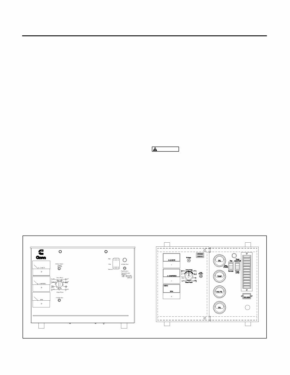
1-1 1. Introduction ABOUT THIS MANUAL This service manual is for the GG Series generator sets (gensets) listed on the front cover. It includes engine and generator troubleshooting guides. En- gine service instructions are in the applicable en- gine service manual. Operating and maintenance instructions are in the applicable Operator’s Manu- al. This manual does not have instructions for servic- ing printed circuit board assemblies. Always re- place a faulty printed circuit board assembly. Attempts to repair a printed circuit board can lead to costly damage to the equipment. This manual contains basic (generic) wiring diagrams and schematics that are included to help in troubleshooting. Service personnel must use the actual wiring diagram and schematic shipped with each unit. The wiring diagrams and schematics that are maintained with the unit should be updated when modifications are made to the unit. Read Safety Precautions and carefully observe all instructions and precautions in this manual. TEST EQUIPMENT Most of the tests in this manual can be done with an AC-DC multimeter, frequency meter, Wheatstone bridge (0.001 ohm precision is necessary for mea- suring stator winding resistance) and load test pan- el. HOW TO OBTAIN SERVICE Always give the complete Model, Specification and Serial number of the generator set as shown on the nameplate when seeking additional service information or replacement parts. The nameplate is located on the side of the generator output box. WARNING Incorrect service or replacement of parts can result in severe personal injury or death, and/or equipment damage. Service per- sonnel must be qualified to perform electrical and mechanical service. Read and follow Safety Precautions, on pages iii and iv. There are separate Engine Control and Trouble- shooting sections for gensets using the Sentinel control or the Detector control (Figure 1-1). Refer to the Table of Contents for specific information relat- ing to your genset. The remaining sections apply to both versions. Detector 12 Control Sentinel Control FIGURE 1-1. CONTROL PANEL CONFIGURATIONS
1-2
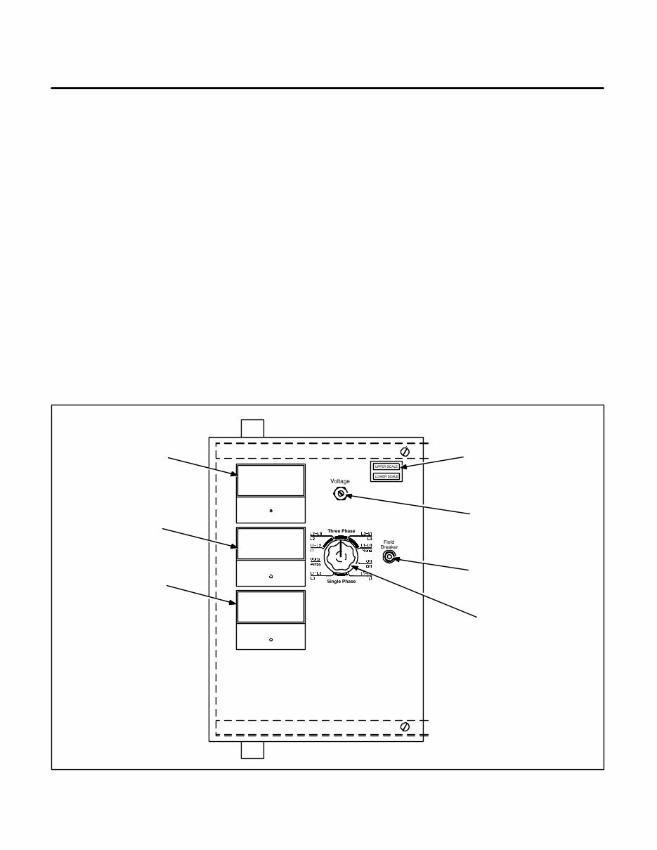
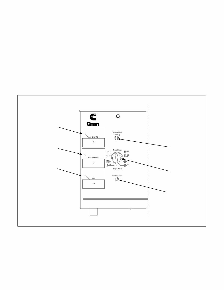
2-1 2. AC Control GENERAL The control box is mounted on top of the generator, facing the rear. Figure 2-1 (Detector Control) and Figure 2-2 (Sentinel Control) point out the compo- nents on the AC control panel. Refer to Section 9 for the AC control wiring diagrams. AC CONTROL PANEL COMPONENTS (DETECTOR CONTROL) Field Circuit Breaker (CB21) The field circuit breaker protects the generator from over-excita- tion. AC Voltmeter (M21) The voltmeter indicates output voltage for the phase selected. AC Ammeter (M22) The ammeter indicates output amperage for the phase selected. Input to the am- meter is from current transformers CT21, CT22, and CT23. Phase Selector Switch (S21) The selector switch is used to select the phase for voltage and amper- age readings. Scale Indicator Lamps (DS21 and DS22) The scale indicator lamps indicate whether to read the upper or lower scales of the voltmeter and ammeter. Frequency Meter (M23) The frequency meter indi- cates output frequency in Hertz (Hz) and engine speed in RPM. Output Voltage Trimmer (R21) The output voltage trimmer can be used to adjust output voltage plus or minus five percent of nominal voltage. UPPER AND LOWER SCALE INDICATOR VOLTAGE ADJUST EXCITATION FIELD BREAKER PHASE SELECTOR SWITCH FREQUENCY/ RPM METER AC AMMETER AC VOLTMETER A-C AMPERES A-C VOLTS HERTZ RPM FIGURE 2-1. AC CONTROL PANEL (DETECTOR CONTROL)
2-2 AC CONTROL PANEL COMPONENTS (SENTINEL CONTROL) AC Voltmeter (M21) The voltmeter indicates output voltage for the phase selected. AC Ammeter (M22) The ammeter indicates output amperage for the phase selected. Input to the am- meter is from current transformers CT21, CT22, and CT23. Frequency/RPM Meter (M23) The frequency me- ter indicates output frequency in Hertz (Hz) and en- gine speed in RPM. Phase Selector Switch (S21) The selector switch is used to select the phase for voltage and amper- age readings. Output Voltage Trimmer (R21) The output voltage trimmer can be used to adjust output voltage plus or minus five percent of nominal voltage. Field Circuit Breaker (CB21) The field circuit breaker protects the generator from over-excita- tion. VOLTAGE ADJUST EXCITATION FIELD BREAKER PHASE SELECTOR SWITCH FREQUENCY/ RPM METER AC AMMETER AC VOLTMETER FIGURE 2-2. AC CONTROL PANEL (SENTINEL CONTROL)
This complete workshop service repair manual for Cummins Onan GGFB GGFC GGHB GGHC GGHD Generator Sets is an essential resource for both professional mechanics and DIY enthusiasts. It covers every service and repair procedure with easy-to-follow step-by-step instructions and pictures, making any job easy to do. You can save a significant amount of money by performing your own repairs using this comprehensive manual.
Once downloaded, the manual is yours to keep forever. You have the flexibility to print out specific pages, chapters, or the entire manual. Additionally, you can easily transfer it to your tablet or smartphone for convenient access.
All models, engines, trim, and transmission types are covered in this manual, ensuring that it caters to a wide range of needs. It includes high-quality content that comprehensively covers all repair procedures from A to Z, making it a valuable asset for anyone working on Cummins Onan GGFB GGFC GGHB GGHC GGHD Generator Sets.
Compatible with all PC and MAC computers, tablets, and mobile phones, this downloadable manual requires only Adobe Reader, which is typically pre-installed on most computers or can be downloaded for free. This ensures easy access to the manual across various devices without any compatibility issues.
Upon payment by Visa, MasterCard, or PayPal, the manual will be instantly emailed to the address provided during checkout, allowing for immediate access and convenience. Customer satisfaction is guaranteed, making this manual a reliable and valuable investment for all your service and repair needs.








 Lifetime Access




