Onan DKC, DKD, MDKC, MDKD Service Manual Cummins Onan Generator Repair Book 981-0502
What's Included?
Lifetime Access
Fast Download Speeds
Online & Offline Access
Access PDF Contents & Bookmarks
Full Search Facility
Print one or all pages of your manual
Caution: This document contains mixed page sizes (8.5 x 11 or 11 x 17), which may affect printing. Please adjust your printer settings according to the size of each page you wish to print. Redistribution or publication of this document by any means, is strictly prohibited.
~ . ~ - . . . . _r ,. ,.- _.. . . , . DKC, DKD MDKC, MDKD Printed in U.S.A. 981 -0502 3-94 Redistribution or publication of this document by any means, is strictly prohibited.
Before operating the generator set, read this manual and become familiar with it and the equipment. Safe and efficient operation can be achieved only if the unit is properly operated and maintained. Many accidents are caused by failure to follow fundamental rules and precautions. The following symbols, found throughout this manual, alert you to potentiallydangerous conditions to the opera- tor, service personnel, or the equipment. This symbol warns of immediate hazards which will result in severe personal injury or death. IQWARP(ING1 Thissymbol refers to a hazard or unsafe practice which can result in severe personal injury or death. b - 1 Thissymbol refers to a hazard or unsafe practice which can result in personal injury or product or propetty damage. Read and observe each of the following safety precautions. FUEL AND FUMES ARE FLAMMABLE Fire, explosion, and personal injury can result from im- proper practices. 0 Do not smoke or allow an open flame or spark-produc- ing equipment near the generator set or fuel tank. Inspect the fuel lines and connections daily for leaks per the maintenance schedule. EXHAUST GASES ARE DEADLY 0 Never sleep in the vehicle with the generator set running unless vehicle is equipped with an operating carbon monoxide detector. 0 Inspect exhaust system daily for leaks per the maintenance schedule. Do not use engine cooling air to heat a compartment. 0 Never operate the generator set inside a building or in an area where exhaust gases could accumulate, such as near a wall or snow bank, or in high grass. When parking, make sure the exhaust outlet is not obstructed. Make sure the generator set is well ventilated. ELECTRICALSHOCK CAN CAUSE SEVERE PERSONAL INJURY OR DEATH Disconnect the negative (-) cable at the starting battery before removing protective shields or touching electrical equipment. Use rubber insulative mats placed on dry wood platforms on the ground or over floors that are metal or concrete when around electrical equipment. Do not wear damp clothing (particularly wet shoes) or allow skin surfaces to be damp when handling electrical equipment. 0 Use extreme caution when working on electrical com- ponents. High voltages can cause injury or death. 0 Tag remote or open switches to avoid accidental clo- sure or starting. 0 DO NOT CONNECT GENERATOR SET DIRECTLY TO ANY BUILDING ELECTRICAL SYSTEM. Hazardous voltages can flow from the generator set into the utility line. This creates a potential for electrocution or property damage. Connect only through an approved device and after building main switch is open. Consult an electrician in regard to emergency power use. MOVING PARTS CAN CAUSE SEVERE PERSONAL INJURY OR DEATH 0 Before starting work on the generator set, disconnect negative (-) cable at the battery. This will prevent accidental arcing or starting. 0 Keep your hands away from moving parts. 0 Make sure that fasteners on the generator set are se- cure. lighten supports and clamps, keep guards in po- sition over fans, etc. 0 Do not wear loose clothing or jewelry while working on generator sets, because they can become caught in moving parts. Jewelry can short out electrical contacts and cause shock or burning. 0 If adjustment must be made while the unit is running, use extreme caution around hot manifolds, moving parts, etc. GENERAL SAFETY PRECAUTIONS 0 Wear safety glasses and protective clothing when servicing batteries. DO NOT SMOKE while servicing batteries. Lead-acid batteries emit a highly explosive hydrogen gas that can be ignited by electrical arcing or by smoking. 0 Have a fire extinguisher rated ABC nearby. Maintain extinguisher properly and become familiar with its use. 0 Benzene and lead, found in some gasoline, have been identified by some state and federal agencies as causing cancgr or reproductive toxicity. When checking, draining or adding gasoline, take care not to ingest, breathe the fumes, or contact gasoline. 0 Used engine oils have been identifiedby some state or federal agencies as causing cancer or reproductive toxicity. When checking or changing engine oil, take care not to ingest, breathe the fumes, or contact used oil. Remove all unnecessary grease and oil from the unit. Accumulated grease and oil can cause overheating and engine damage, which presents a potential fire hazard. Do not store anything in the generator set compad- ment such as oil or gas cans, oily rags, chains, wooden blocks, portable propane cylinders, etc. Afire could re- sult or the generator set operation (cooling, noise and vibration) may be adversely affected. Keep the com- partment floor clean and dry. Do not work on this equipment when mentally or physically .fatigued, or after consuming any alcohol o- drug that makes the operation of equipment unsafe. .I , , RGA-OP' Redistribution or publication of this document by any means, is strictly prohibited.
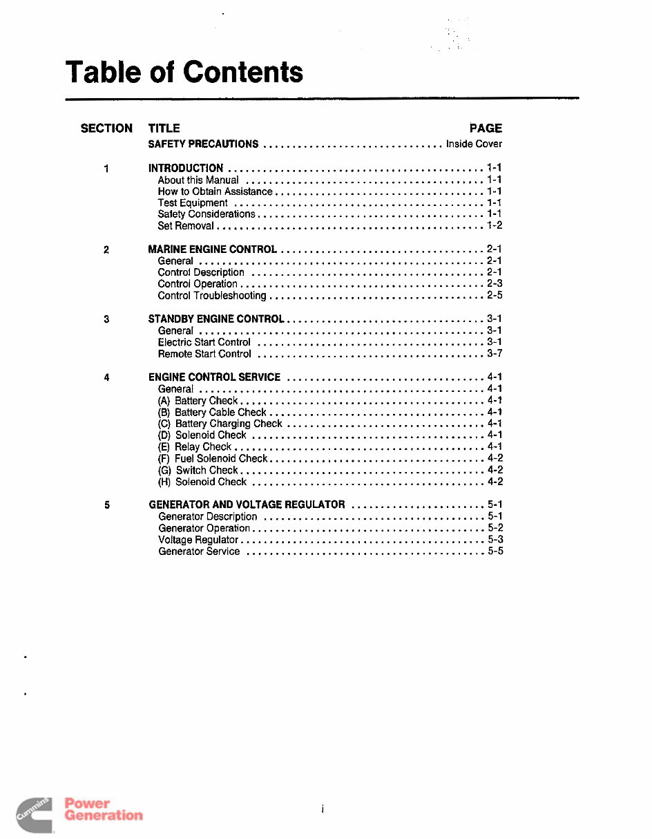
Table of Contents SECTION TITLE PAGE SAFETY PRECAUTIONS ............................... Inside Cover 1 INTRODUCTION ............................................ 1-1 About this Manual ......................................... 1-1 How to Obtain Assistance .................................... 1-1 Test Equipment ........................................... 1-1 Safety Considerations ....................................... 1-1 Set Removal .............................................. 1-2 2 3 4 5 MARINE ENGINE CONTROL ................................... 2-1 General ................................................. 2-1 Control Description ........................................ 2.1 Control Operation .......................................... 2-3 Control Troubleshooting ..................................... 2-5 General ................................................. 3-1 Electric Start Control ....................................... 3-1 Remote Start Control ....................................... 3-7 STANDBY ENGINE CONTROL .................................. 3.1 ENGINE CONTROL SERVICE .................................. 4.1 General ................................................. 4-1 (A) BatteryCheck .......................................... 4-1 (B) Battery Cable Check ..................................... 4.1 (C) Battery Charging Check .................................. 4.1 (D) Solenoid Check ....................................... -4-1 (E) Relay Check ........................................... 4.1 (F) Fuel Solenoid Check ..................................... 4.2 (G) Switchcheck .......................................... 4-2 (H) Solenoid Check ....................................... -4-2 GENERATOR AND VOLTAGE REGULATOR ....................... 5-1 Generator Description ...................................... 5-1 Generator Operation ........................................ 5-2 Voltage Regulator .......................................... 5-3 Generator Service ......................................... 5-5 i Redistribution or publication of this document by any means, is strictly prohibited.
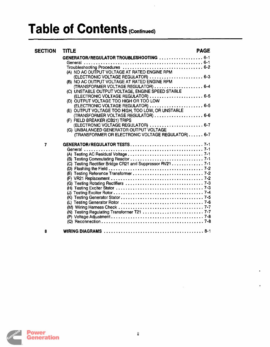
Table Of COIltentS (Continued) SECTION TITLE PAGE GENERATOR/REGULATOR TROUBLESHOOTING .................. 6-1 General ................................................. 6-1 Troubleshooting Procedures ................................. 6-2 (A) NO AC OUTPUT VOLTAGE AT RATED ENGINE RPM (B) NO AC OUTPUT VOLTAGE AT RATED ENGINE RPM (C) UNSTABLE OUTPUT VOLTAGE. ENGINE SPEED STABLE (D) OUTPUT VOLTAGE TOO HIGH OR TOO LOW (E) OUTPUT VOLTAGE TOO HIGH. TOO LOW. OR UNSTABLE (F) FIELD BREAKER (CB21) TRIPS (G) UNBALANCED GENERATOR OUTPUT VOLTAGE (ELECTRONICVOLTAGE REGULATOR) ...................... 6.3 (TRANSFORMER VOLTAGE REGULATOR) .................... 6-4 (ELECTRONIC VOLTAGE REGULATOR) ...................... 6-5 (ELECTRONIC VOLTAGE REGUMTOR) ...................... 6-5 (TRANSFORMER VOLTAGE REGULATOR) .................... 6-6 (ELECTRONICVOLTAGE REGULATOR) ...................... 6 . 7 (TRANSFORMER OR ELECTRONIC VOLTAGE REGULATOR) ...... 6-7 7 GENERATOR/REGULATOR TESTS .............................. 7-1 General ................................................. 7-1 (A) Testing AC Residual Voltage ............................... 7-1 (B) Testing Commutating Reactor .............................. 7 . 1 (C) Testing Rectifier Bridge CR21 and Suppressor RV21 ............. 7-1 (D) Flashing the Field ....................................... 7-2 (E) Testing Reference Transformer ............................. 7-2 (F) VR21 Replacement ...................................... 7-2 (G) Testing Rotating Rectifiers ................................ 7-3 (H) Testing Exciter Stator .................................... 7-3 (J) Testing Exciter Rotor ..................................... 7-4 (K) Testing Generator Stator .................................. 7-5 (L) Testing Generator Rotor .................................. 7-6 (M) Wiring Harness Check ................................... 7-7 (N) Testing Regulating Transformer T21 ......................... 7-7 (P) Voltage Adjustment ...................................... 7-8 (a) Reconnection .......................................... 7-8 8 WIRING DIAGRAMS ......................................... 8-1 ii Redistribution or publication of this document by any means, is strictly prohibited.
Section 1 Introduction ABOUT THIS MANUAL For servicing purposes, the generator set can be divided into three basic parts: the engine, the generator, and the control. This manual contains troubleshooting and repair information for the generator and the control. Refer to the Engine Service Manual (981-0501) when servicing the engine. Study this manual carefully and observe all the warn- ings and cautions throughout the manual. Knowing the generator set, using it properly, and following a regular maintenance schedule can result in longer unit life, better performance and safer operation. Information for printed circuit board repair is limited because it is more efficient to replace the boards in the field and repair them at the factory. Application of meters or hot soldering irons to printed circuit boards by other than qualified service personnel can cause unneces- sary and expensive damage. This manual contains basic wiring diagrams and sche- matics that are included to help in troubleshooting. Ser- vice personnel should use the actual wiring diagram and schematic shipped with each unit. The wiring dia- grams and schematics that are maintained with the unit should be updated when modifications are made to the unit. HOW TO OBTAIN ASSISTANCE Always give the complete model number and serial number as shown on the Onan nameplate when seek- ing additional service information or replacement parts. TEST EQUIPMENT Most of the test procedures in this manual can be per- formed with a multimeter such as the Simpson Model 260 VOM or with a digital VOM. Additional instruments used to service generator sets that should be available are: AC Voltmeter DC Voltmeter Frequency Meter Jumper Leads Load Test Panel Megger or Insulation Resistance Meter Frequency Meter or Strobotach Variac Wheatstone Bridge or Digital Ohmmeter Incorrect service or replacement of l ZCEHE4 parts can result in severe personal injury, death, and /or equipment damage. Serviceper- sonnel must be qualified to perform electrical and mechanical service. SAFETY CONSIDERATIONS Always consider the safety aspects of any service procedure. Generator sets present several safety hazards that the service person must be aware of to safely completethe job. Readthrough the safety precau- tions listed on the inside cover and familiarize yourself with the hazards shown in Table 1-1. Once the hazards are known, approach the job with a safety conscious attitude. Being safety conscious is the most effective way to avoid injury to yourself or others. Reduce the chance that an accident will occur by adopting the following safeguards. Safeguards to Avoid Hazards Use personal protection - Protect your body by wearing the appropriate safety equipment. Protec- tive clothing includes safety shoes, gloves, safety glasses, and hard hats. Leave rings and jewelry off and do not wear loose clothing that might get caught on equipment. 0 Work to Reduce the Hazard - The workshop area and all pieces of equipment used can contribute to reducing the hazard potential. Keep guards and shields in place on machinery and maintain equip- ment in good working order. Store flammable liq- uids in approved containers awayfrom open flame, spark, pilot light, cigarette, or other ignition source. Keep the workshop clean and well-lighted, and provide adequate ventilation. Keep fire extinguisher and safety equipment nearby and be prepared to respond to an emergency. 0 Develop Safe Work Habits - Unsafe actions are identifiedas the source of most accidents involving the use of tools and machines. Be familiar with the equipment and know how to use it safely. Use the correct tool for the job and check its condition before starting. Observe the warnings and cautions in this manual and take special precautions when working around electrical equipment. Do not work alone if possible and do not take risks. 1-1 Redistribution or publication of this document by any means, is strictly prohibited.
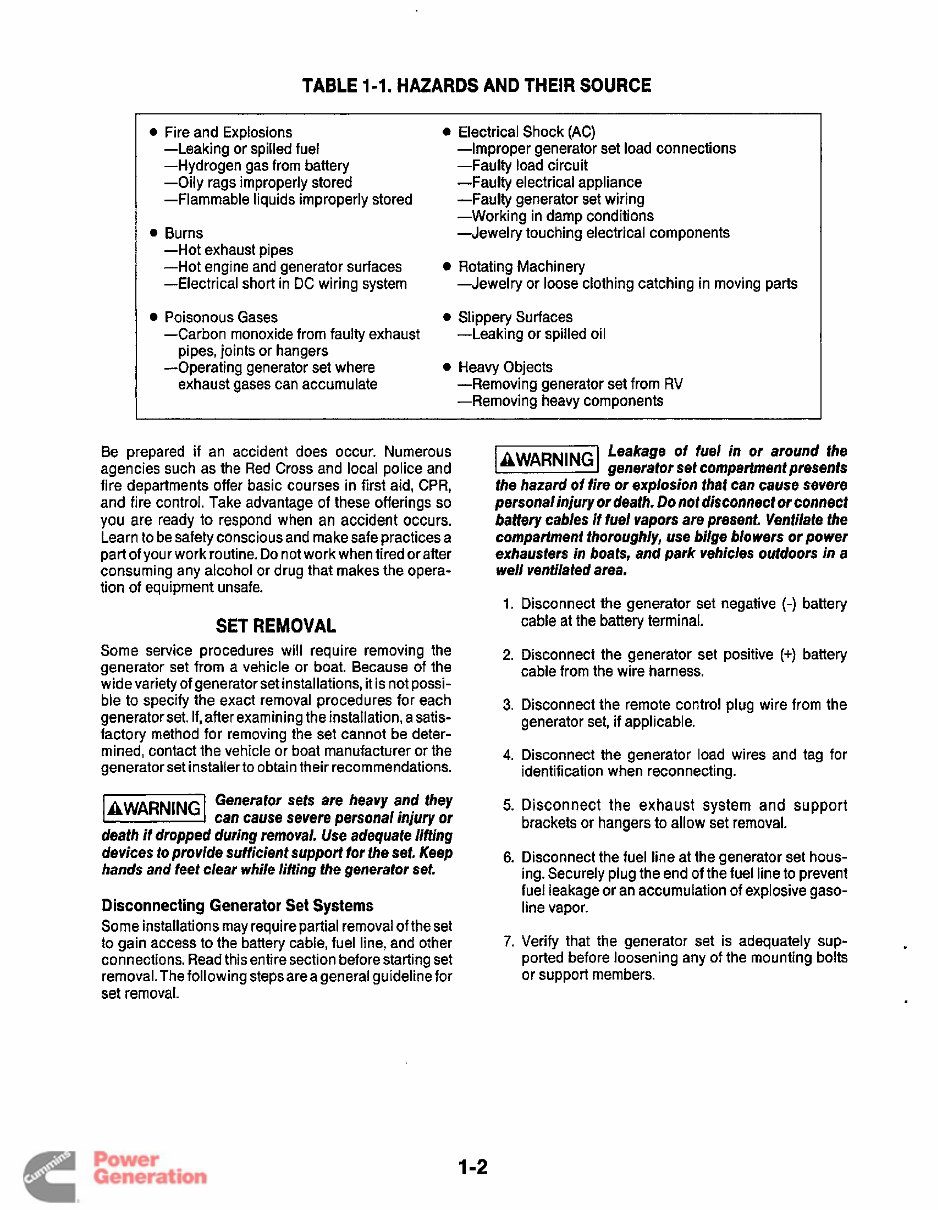
TABLE 1-1. HAZARDS AND THEIR SOURCE 0 Fire and Explosions -Leaking or spilled fuel -Hydrogen gas from battery -Oily rags improperly stored -Flammable liquids improperly stored 0 Burns -Hot exhaust pipes -Hot engine and generator surfaces -Electrical short in DC wiring system -Carbon monoxide from faulty exhaust pipes, joints or hangers -Operating generator set where exhaust gases can accumulate Poisonous Gases 0 Electrical Shock (AC) -Improper generator set load connections -Faulty load circuit -Faulty electrical appliance -Faulty generator set wiring -Working in damp conditions -Jewelry touching electrical components -Jewelry or loose clothing catching in moving parts -Leaking or spilled oil Rotating Machinery 0 Slippery Surfaces 0 Heavy Objects -Removing generator set from RV -Removing heavy components Be prepared if an accident does occur. Numerous agencies such as the Red Cross and local police and fire departments offer basic courses in first aid, CPR, and fire control. Take advantage of these offerings so you are ready to respond when an accident occurs. Learn to be safety conscious and make safe practices a part of your work routine. Do not work when tired or after consuming any alcohol or drug that makes the opera- tion of equipment unsafe. SET REMOVAL Some service procedures will require removing the generator set from a vehicle or boat. Because of the wide variety of generator set installations, it is not possi- ble to specify the exact removal procedures for each generator set. If, after examining the installation, a satis- factory method for removing the set cannot be deter- mined, contact the vehicle or boat manufacturer or the generator set installerto obtain their recommendations. Generator sets are heavy and they lZEEEl can cause severe personal injury or death if dropped during removal. Use adequate lifting devices to provide sufficient support for the set. Keep hands and feet clear while lifting the generator set. DisconnectingGenerator Set Systems Some installations may requirepartial removal of the set to gain access to the battery cable, fuel line, and other connections. Read this entire section before starting set removal. The following steps are a general guideline for set removal. Leakage of fuel in or around the [BWARNINGI generator set compartmentpresents the hazard of fire or explosion that can cause severe personalinjury or death. Do not disconnect or connect battery cables if fuel vapors are present. Ventilate the compartment thoroughly, use bilge blowers or power exhausters in boats, and park vehicles outdoors in a well ventilated area. 1. Disconnect the generator set negative (-) battery 2. Disconnect the generator set positive (+) battery cable at the battery terminal. cable from the wire harness. 3. Disconnect the remote control plug wire from the generator set, if applicable. 4. Disconnect the generator load wires and tag for identificationwhen reconnecting. 5. Disconnect the exhaust system and support brackets or hangers to allow set removal. 6. Disconnect the fuel line at the generator set hous- ing. Securely plug the end of the fuel line to prevent fuel leakage or an accumulation of explosive gaso- line vapor. 7. Verify that the generator set is adequately sup- ported before loosening any of the mounting bolts or support members. 1 -2 Redistribution or publication of this document by any means, is strictly prohibited.
Leakage of fuel presents fhe hazard @!@!!%I of fire or explosion that can cause severe personal injury or death. Make certain all fuel line openings are plugged to prevent gasoline vapor from accumulating. Before disconnecting the fuel line, be certain thereare no ignition sources such as flame, spark, pilot light, cigareite, etc., near the generatorset. Keep an ABC type fire extinguisher nearby. When reinstallingthe generator set, be sure all mount- ing hardware, and electrical, exhaust, and fuel system componentsareconnectedexactly as they were before removal. Refer to the appropriate installation manual during reinstallation for important safety precautions. Check for oil and fuel leaks. Check exhaust system audibly and visually with the generator set running. Repair any leaks immediately. Replaceworn, damaged, or corroded exhaust and fuel line components before leaks occur. 1-3 Redistribution or publication of this document by any means, is strictly prohibited.
Redistribution or publication of this document by any means, is strictly prohibited.
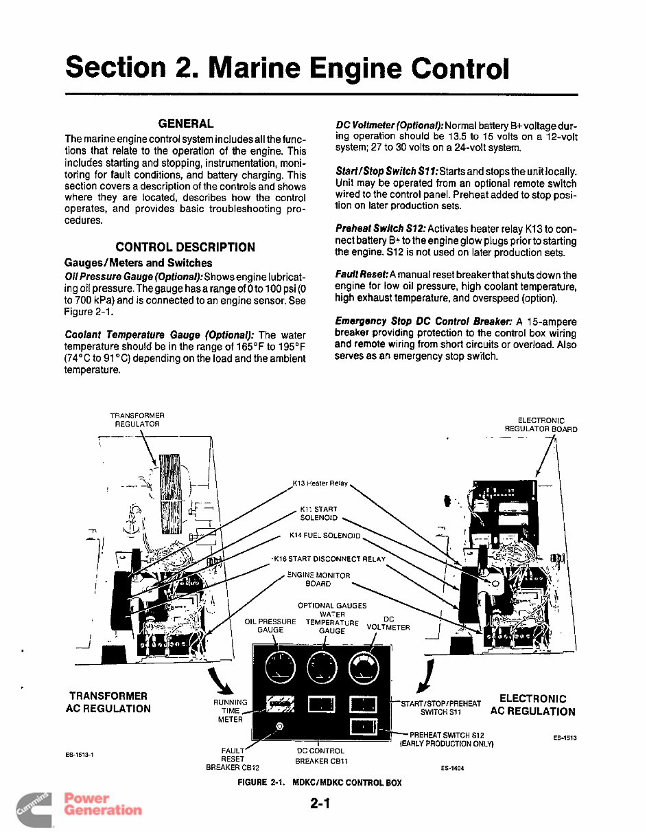
Section 2. Marine Engine Control GENERAL The marine engine control system includesall thefunc- tions that relate to the operation of the engine. This includes starting and stopping, instrumentation, moni- toring for fault conditions, and battery charging. This section covers a description of the controls and shows where they are located, describes how the control operates, and provides basic troubleshooting pro- cedures. CONTROL DESCRIPTION Gauges/Meters and Switches Oil Pressure Gauge (0ptional):Shows engine lubricat- ing oil pressure. The gauge hasa range of 0 to 100 psi (0 to 700 kPa) and is connected to an engine sensor. See Figure 2-1. Coolant Temperafure Gauge (Optional): The water temperature should be in the range of 165OF to 195°F (74°C to 91 "C) depending on the load and the ambient temperature. TRANSFORMER REGULATOR DC Voltmeter (Optional): Normal battery B+ voltage dur- ing operation should be 13.5 to 15 volts on a 12-volt system; 27 to 30 volts on a 24-volt system. Starf/Stop Switch S77:Starts and stopsthe unit locally. Unit may be operated from an optional remote switch wired to the control panel. Preheat added to stop posi- tion on later production sets. Preheat Switch S72: Activates heater relay K13 to con- nect battery B+ to the engine glow plugs prior to starting the engine. S12 is not used on later production sets. Fault Reset:A manual reset breakerthat shuts down the engine for low oil pressure, high coolant temperature, high exhaust temperature, and overspeed (option). Emergency Stop DC Control Breaker: A 15-ampere breaker providing protection to the control box wiring and remote wiring from short circuits or overload. Also serves as an emergency stop switch. EL ECTR 0 N I C REGULATOR BOARD /\ Redistribution or publication of this document by any means, is strictly prohibited.
The Onan Cummins DKC, DKD, MDKC, MDKD Generators Service Repair Manual is a comprehensive workshop manual that provides detailed servicing instructions for your Onan Cummins Generator. It offers complete information on repair, servicing, preventative maintenance, and troubleshooting procedures. This manual is an indispensable source of detailed maintenance and repair information, featuring photos, illustrations, and step-by-step instructions to guide you through the entire repair process.
Useful for both professional mechanics and DIY enthusiasts, this manual covers the following Onan Cummins Generator Models: DKC, DKD, MDKC, MDKD.
Key features of this manual include:
Instant access with no waiting time
Easy navigation for quick identification of service repair procedures
Detailed illustrations, exploded diagrams, drawings, and photos to guide you through every service repair procedure
File Format: PDF
Pages: 71
Printable: Yes
Language: English
Subjects covered in this Onan Cummins Generator Complete Service Shop Manual:
ENGINE AND ACCESSORIES
GENERATOR
SAFETY PRECAUTIONS
CONTROL PANEL
OPERATION
PERIODIC MAINTENANCE
GENERATOR SET CONTROL
SPECIFICATIONS
WIRING DIAGRAM
After purchasing the service manual, you can instantly access and view it. The manual is fully printable, allowing you to print pages whenever needed.
Recently Viewed
5,521,897Happy Clients
2,594,462eManuals
1,120,453Trusted Sellers
15Years in Business
Price:
Actual Price:
Onan DKC, DKD, MDKC, MDKD Service Manual Cummins Onan Generator Repair Book 981-0502