Onan BGD & NHD Generator Sets Spec H Service Manual Cummins Generator Repair Book 965-0500
What's Included?
Lifetime Access
Fast Download Speeds
Online & Offline Access
Access PDF Contents & Bookmarks
Full Search Facility
Print one or all pages of your manual
Caution: This document contains mixed page sizes (8.5 x 11 or 11 x 17), which may affect printing. Please adjust your printer settings according to the size of each page you wish to print.
Service Manual Model BGD and NHD Generator Sets, Beginning Spec H Printed in U.S.A. 11-95 965-0500
Safety Precautions Thoroughly read the OPERATOR’S MANUAL before operating the genset. Safe operation and top perfor- mance can be obtained only with proper operation and maintenance. The following symbols in this Manual alert you to poten- tial hazards to the operator, service person and equip- ment. Alerts you to an immediate hazard which will result in severe personal injury or death. Alerts you to a hazard or unsafe prac- tice which can result in severe personal injury or death. Alerts you to a hazard or unsafe prac- tice which can result in personal injury or equipment damage. Electricity, fuel, exhaust, moving parts and batteries present hazards which can result in severe personal inju- ry or death. GENERAL PRECAUTIONS • Keep ABC fire extinguishers handy. • Make sure all fasteners are secure and torqued properly. • Keep the genset and its compartment clean. Ex- cess oil and oily rags can catch fire. Dirt and gear stowed in the compartment can restrict cooling air. • Before working on the genset, disconnect the nega- tive (- ) battery cable at the battery to prevent start- ing. • Use caution when making adjustments while the genset is running—hot, moving or electrically live parts can cause severe personal injury or death. • Used engine oil has been identified by some state and federal agencies as causing cancer or repro- ductive toxicity. Do not ingest, inhale, or contact used oil or its vapors. • Benzene and lead in some gasolines have been identified by some state and federal agencies as causing cancer or reproductive toxicity. Do not to in- gest, inhale or contact gasoline or its vapors. • Do not work on the genset when mentally or physi- cally fatigued or after consuming alcohol or drugs. • Carefully follow all applicable local, state and feder- al codes. GENERATOR VOLTAGE IS DEADLY! • Generator output connections must be made by a qualified electrician in accordance with applicable codes. • The genset must not be connected to the public util- ity or any other source of electrical power. Connec- tion could lead to electrocution of utility workers, damage to equipment and fire. An approved switch- ing device must be used to prevent interconnec- tions. • Use caution when working on live electrical equip- ment. Remove jewelry, make sure clothing and shoes are dry and stand on a dry wooden platform on the ground or floor. FUEL IS FLAMMABLE AND EXPLOSIVE • Keep flames, cigarettes, sparks, pilot lights, electri- cal arc-producing equipment and switches and all other sources of ignition well away from areas where fuel fumes are present and areas sharing ventilation. • Fuel lines must be secured, free of leaks and sepa- rated or shielded from electrical wiring. • Use approved non-conductive flexible fuel hose for fuel connections at the genset. ENGINE EXHAUST IS DEADLY! • Learn the symptoms of carbon monoxide poisoning in this Manual. • Never sleep in the vehicle while the genset is run- ning unless the vehicle has a working carbon mon- oxide detector. • The exhaust system must be installed in accor- dance with the genset Installation Manual. • Do not use engine cooling air to heat the vehicle in- terior. • Make sure there is ample fresh air when operating the genset in a confined area. MOVING PARTS CAN CAUSE SEVERE PERSONAL INJURY OR DEATH • Do not wear loose clothing or jewelry near moving parts such as PTO shafts, fans, belts and pulleys. • Keep hands away from moving parts. • Keep guards in place over fans, belts, pulleys, etc. BATTERY GAS IS EXPLOSIVE • WEAR SAFETY GLASSES and DO NOT SMOKE while servicing batteries. • When disconnecting or reconnecting battery cables, always disconnect the negative (- ) battery cable first and reconnect it last to reduce arcing.
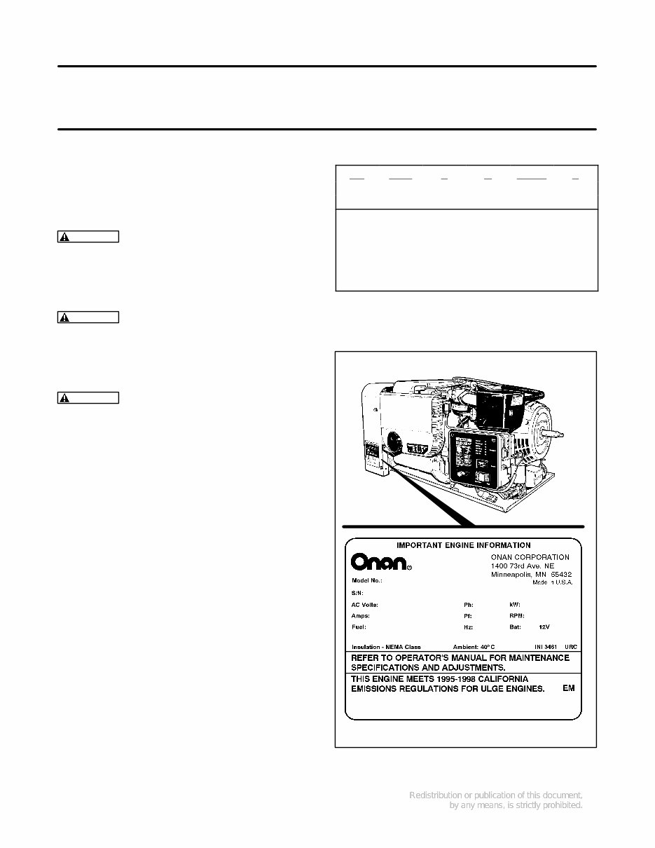
3 Introduction This is the service manual for the Series BGD and NHD generator sets (gensets) for commercial ve- hicles. Read and carefully observe all of the instruc- tions and precautions in this manual. Figure 2 illus- trates a typical genset. WARNING Improper service or parts replace- ment can lead to severe personal injury or death and to damage to equipment and property. Ser- vice personnel must be qualified to perform electrical and mechanical service. WARNING Unauthorized modifications or re- placement of fuel, exhaust, air intake or speed control system components that affect engine emissions are prohibited by law in the State of California. WARNING LPG (liquified petroleum gas) is flammable and explosive and can cause as- phyxiation. NFPA 58, Section 1.6 requires all persons handling LPG to be trained in proper handling and operating procedures. See the Operator’s Manual for instructions concern- ing operation, maintenance and storage and for rec- ommendations concerning engine lubricating oil and fuel. See the Installation Manual for important recom- mendations concerning the installation and for a list of the installation codes and standards for safety which may be applicable. See the Parts Manual for parts identification num- bers and required quantities and for exploded views of the genset subassemblies. Genuine Onan re- placement parts are recommended for best results. When contacting Onan for parts, service or product information, be ready to provide the model number and the serial number, both of which appear on the genset nameplate. See Table 1 for the significance of each character of the model number and Figure 1 for how the model and serial numbers are displayed on the nameplate. TABLE 1. MODEL NUMBER 6.5 NHD F B 30502 L | | | | | | 1 2 3 4 5 6 1. Rated Power in Kilowatts 2. Genset Family 3. Starting Method Code 4. Voltage and Frequency Code 5. Options and Special Features Code 6. Spec Letter designating modifications SN5980U1G2RA 980 cc 6.5NHDFB30502L A953123456 FIGURE 1. TYPICAL NAMEPLATE
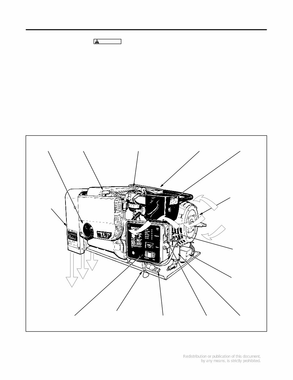
4 WARNING EXHAUST GAS IS DEADLY! All engine exhaust contains contain carbon monoxide, an odorless, colorless, poisonous gas that can cause unconsciousness and death. Symptoms of carbon monoxide poisoning include: • Dizziness • Nausea • Headache • Vomiting • Weakness and Sleepiness • Inability to Think Coherently IF YOU EXPERIENCE ANY OF THESE SYMPTOMS, GET INTO FRESH AIR IMMEDIATELY. If symp- toms persist, seek medical attention. Shut down the genset and do not operate it until it has been inspected and repaired. Never sleep in the vehicle while the genset is running unless the vehicle has a working carbon mon- oxide detector. The exhaust system must be installed in accordance with the genset Installation Manual. Make sure there is ample fresh air when operating the genset in a confined area. THE EXHAUST OUTLET FLANGE IS ACCESSIBLE THROUGH THE WARM AIR DISCHARGE OPENING BATTERY CABLE CONNECTIONS (HIDDEN) WARM AIR DISCHARGE CONTROL PANEL COOLING AIR AIR CLEANER REMOTE START ENABLE SWITCH CONNECTOR BLOWER HOUSING SPARK PLUG (HIDDEN) SPARK PLUG CARBURETOR AND GOVERNOR ADJUSTMENTS OIL FILTER GASOLINE FUEL PUMP CONTROL FUSE F1 REMOTE CONTROL CONNECTOR PLUG LINE CIRCUIT BREAKERS AC VOLTAGE REGULATOR (1-PHASE) FIGURE 2. TYPICAL GENSET
5 Specifications GASOLINE MODELS BGD NHD GENERATOR: 4-Pole Revolving Field, Self-Excited, Electronically Regulated Power (watts) 4500 4000 6500 5000 Frequency (Hertz) 60 50 60 50 120/240 Volt Single-Phase Output Current (amperes @ 1.0 PF) 37.5/18.8 33.3/16.6 54/57 41.7/20.8 120/240 Volt Three-Phase Output Current (amperes @ 1.0 PF) 21.7/10.8 - 31.3/15.6 - 220/380 Volt Three-Phase Output Current (amperes @ 1.0 PF) - 10.5/6.1 - 13.1/7.6 Speed (RPM) 1800 1500 1800 1500 FUEL CONSUMPTION: No load gph (l/h) Half load gph (l/h) Full load gph (l/h) 0.3 (1.1) 0.5 (1.9) 0.8 (3.0) 0.3 (1.1) 0.5 (1.9) 0.8 (3.0) 0.4 (1.5) 0.7 (2.6) 1.3 (4.9) 0.4 (1.5) 0.7 (2.6) 1.0 (3.8) ENGINE: 2-Cylinder Opposed, 4-Cycle, Spark-Ignited, Side-Valve, Air Cooled Bore 3.250 inch (83 mm) 3.563 inch (90 mm) Stroke 2.875 inch (73 mm) 3.000 inch (76 mm) Displacement 48 inch 3 (782 cc) 60 inch 3 (980 cc) Compression Ratio 7.0 : 1 7.0 : 1 Min. Cylinder Compression Test Pressure 75 psi (517 kPa) 75 psi (517 kPa) Oil Capacity (with filter)* 3.5 quart (3.3 l) 3.5 quart (3.3 l) Intake Valve Clearance (Cold) 0.005 inch (0.13 mm) 0.005 inch (0.13 mm) Exhaust Valve Clearance (Cold) 0.013 inch (0.33 mm) 0.013 inch (0.33 mm) Spark Plug Gap 0.025 inch (0.64 mm) 0.025 inch (0.64 mm) Spark Plug Tightening Torque 8 lbs-ft (10 N-m) 8 lbs-ft (10 N-m) Ignition Timing (Beginning Spec L) 12° BTDC non-adjustable 12° BTDC non-adjustable Ignition Timing (Prior to Spec L) 14°-18° BTDC non-adjustable 14°-18° BTDC non-adjustable Max. Fuel Supply Pressure at Carburetor 6 psi (41 kPa) 6 psi (41 kPa) Max. Fuel Pump Lift 3 feet (0.9 m) 3 feet (0.9 m) Fuel Fitting 5/16 inch OD Hose Barb 5/16 inch OD Hose Barb Exhaust Tailpipe Requirements 1-3/8 inch ID, 18 Ga Steel Tubing 1-3/8 inch ID, 18 Ga Steel Tubing CONTROL AND CRANKING SYSTEM: 12 VDC Nominal Battery Voltage 12 volts 12 volts Minimum Battery Cold Cranking Capacity: Above/Below Freezing 360/450 amperes 360/450 amperes Nominal Regulated-Voltage Battery Charging Output 10 amperes 10 amperes Control Fuse F1 (Beginning Spec J) 10 amperes mini-bayonet 10 amperes mini-bayonet Control Fuse F1 (Spec H only) 5 amperes slow-blow 5 amperes slow-blow Ignition/Choke F2 (Spec H only) 10 amperes mini-bayonet 10 amperes mini-bayonet * -See Periodic Maintenance for oil filling instructions.
6 LPG MODELS BGD NHD GENERATOR: 4-Pole Revolving Field, Self-Excited, Electronically Regulated Power (watts) 4500 4000 6300 5000 Frequency (Hertz) 60 50 60 50 120/240 Volt Single-Phase Output Current (amperes @ 1.0 PF) 37.5/18.8 33.3/16.6 52.5/26.3 41.7/20.8 120/240 Volt Three-Phase Output Current (amperes @ 1.0 PF) 21.7/10.8 - 30.3/15.2 - 220/380 Volt Three-Phase Output Current (amperes @ 1.0 PF) - 10.5/6.1 - 13.1/7.6 Speed (RPM) 1800 1500 1800 1500 FUEL CONSUMPTION: No load lbs/h (kg/h) Half load lbs/h (kg/h Full load lbs/h (kg/h 1.8 (0.8) 3.1 (1.4) 4.4 (2.0) 1.5 (0.7) 2.6 (1.2) 4.0 (1.8) 2.2 (1.0) 3.8 (1.7) 6.6 (3.0) 2.0 (0.9) 3.5 (1.6) 5.1 (2.3) ENGINE: 2-Cylinder Opposed, 4-Cycle, Spark-Ignited, Side-Valve, Air Cooled Bore 3.250 inch (83 mm) 3.563 inch (90 mm) Stroke 2.875 inch (73 mm) 3.000 inch (76 mm) Displacement 48 inch 3 (782 cc) 60 inch 3 (980 cc) Compression Ratio 7.0 : 1 7.0 : 1 Min. Cylinder Compression Test Pressure 75 psi (517 kPa) 75 psi (517 kPa) Oil Capacity (with filter)* 3.5 quarts (3.3 l) 3.5 quarts (3.3 l) Intake Valve Clearance (Cold) 0.005 inch (0.13 mm) 0.005 inch (0.13 mm) Exhaust Valve Clearance (Cold) 0.013 inch (0.33 mm) 0.013 inch (0.33 mm) Spark Plug Gap 0.025 inch (0.64 mm) 0.025 inch (0.64 mm) Spark Plug Tightening Torque 8 lbs-ft (10 N-m) 8 lbs-ft (10 N-m) Ignition Timing (Beginning Spec L) 12° BTDC non-adjustable 12° BTDC non-adjustable Ignition Timing (Prior to Spec L) 14°-18° BTDC non-adjustable 14°-18° BTDC non-adjustable LPG Vapor Supply Pressure Range (Vapor-Withdrawal Only) 9 to 13 inch (229 to 330 mm) W.C. (water column) 9 to 13 inch (229 to 330 mm) W.C. (water column) LPG Connection for Vapor Withdrawal 3/4 inch NPT Tapping 3/4 inch NPT Tapping LPG Connection for Liquid Withdrawal 1/4 inch NPTF Tapping 1/4 inch NPTF Tapping Exhaust Tailpipe Requirements 1-3/8 inch ID, 18 Ga Steel Tubing 1-3/8 inch ID, 18 Ga Steel Tubing CONTROL AND CRANKING SYSTEM: 12 VDC Nominal Battery Voltage 12 volts 12 volts Minimum Battery Cold Cranking Capacity: Above/Below Freezing 360/450 amperes 360/450 amperes Nominal Regulated-Voltage Battery Charging Output 10 amperes 10 amperes Control Fuse F1 (Beginning Spec J) 10 amperes mini-bayonet 10 amperes mini-bayonet Control Fuse F1 (Spec H only) 5 amperes slow-blow 5 amperes slow-blow Ignition/Choke F2 (Spec H only) 10 amperes mini-bayonet 10 amperes mini-bayonet * -See Periodic Maintenance for oil filling instructions.
7 Tolerances and Clearances All dimensional tolerances and clearances are in inches (millimeters) unless otherwise indicated MODEL BDG MODEL NHD Cylinder Bore (Standard Size)* 3.2490-3.2500 (82.52-82.55) 3.5625-3.5635 (90.49-90.51) Cylinder Taper (maximum) 0.005 (0.13) 0.003 (0.08) Cylinder Out of Round (maximum) 0.003 (0.08) 0.003 (0.08) Clearance in Cylinder 0.0033-0.0053 (0.084-0.135) 0.0070-0.0090 (0.178-0.229) Ring Gap 0.010-0.020 (0.25-0.50) 0.010-0.020 (0.25-0.50) #1 (Top) Piston Ring Groove Width 0.0602-0.0612 (1.53-1.55) 0.0602-0.0612 (0.25-0.50) #2 Piston Ring Groove Width 0.0602-0.0612 (1.53-1.55) 0.0602-0.0612 (1.53-1.55) #3 Piston Ring Groove Width 0.1193-0.1203 (3.03-3.06) 0.1193-0.1203 (3.03-3.06) #1 (Top) Piston Ring Groove Width Prior to Spec F 0.080-0.081 (2.03-2.06) 0.080-0.081 (2.03-2.06) #2 Piston Ring Groove Width Prior to Spec F 0.080-0.081 (2.03-2.06) 0.080-0.081 (2.03-2.06) #3 Piston Ring Groove Width Prior to Spec F 0.188-0.189 (4.78-4.80) 0.188-0.189 (4.78-4.80) #1 (Top) Piston Ring Side Clearance 0.003-0.008 (0.076-0.203) 0.002-0.008 (0.051-0.203) Piston Pin Diameter 0.6875-0.6877 (17.46-17.47) 0.7500-0.7502 (19.05-19.06) Piston Pin Fit in Rod 0.0002-0.007 (0.005-0.018) 0.0002-0.0008 (0.005-0.020) Connecting Rod Side Clearance 0.002-0.016 (0.051-0.406) 0.002-0.016 (0.051-0.406) Connecting Rod Bearing Clearance 0.0020-0.0033 (0.051-0.084) 0.002-0.0033 (0.051-0.084) Crankshaft Main Bearing Journal Diameter 1.9992-2.0000 (50.780-50.800) 1.9992-2.0000 (50.780-50.800) Crankshaft Rod Journal Bearing Diameter 1.6252-1.6260 (41.280-41.300) 1.6252-1.6260 (41.280-41.300) Crankshaft Main Bearing Diameter 2.0024-2.0034 (50.860-50.886) 2.0015-2.0040 (50.838-50.902) Crankshaft Main Bearing Clearance 0.0024-0.0042 (0.061-0.107) 0.0024-0.0042 (0.061-0.107) Crankshaft End Play 0.006-0.012 (0.15-0.30) 0.006-0.012 (0.15-0.30) * - The bore is 0.005 inch oversize if the engine serial number has suffix “E”.
The Onan Cummins BGD & NHD Generator Sets Beginning Spec H Service Repair Manual is a comprehensive workshop manual that provides detailed servicing instructions for your Onan Cummins Generator. It includes complete information on repair, servicing, preventative maintenance, and troubleshooting procedures. This manual features step-by-step instructions, photos, and illustrations to guide you through the entire repair process, making it an indispensable source of detailed maintenance and repair information for professional mechanics and DIY enthusiasts alike.
Key features of this manual include:
Instant access with no waiting time
Easy navigation for quick identification of service repair procedures
Detailed illustrations, exploded diagrams, drawings, and photos to guide you through every service repair procedure
File Format: PDF
Pages: 108
Printable: Yes
Language: English
This manual covers the following Onan Cummins Generator Models:
BGD & NHD Generator Sets Beginning Spec H
Subjects covered in this manual:
Engine and Accessories, including major engine service, engine sensors, governor actuator, exhaust manifold, fuel system, starter, and battery charging alternator
Generator, including testing, disassembly, reassembly, reconnecting, and line circuit breakers
Safety precautions
Control panel operation, engine oil recommendations, engine coolant, and periodic maintenance
Generator set control, DC circuit breaker, engine oil pressure sender, engine coolant temperature sender, governor actuator, starter relay
Specifications and wiring diagram
Upon purchasing this service manual, you will have instant access to the fully printable PDF, allowing you to view and print pages whenever needed.
Recently Viewed
5,521,897Happy Clients
2,594,462eManuals
1,120,453Trusted Sellers
15Years in Business
Price:
Actual Price:
Onan BGD & NHD Generator Sets Spec H Service Manual Cummins Generator Repair Book 965-0500