

ONAN EngineS BG Parts and Service Manual
What's Included?
Fast Download Speeds
Online & Offline Access
Access PDF Contents & Bookmarks
Full Search Facility
Print one or all pages of your manual
Service
and
Parts
Manual
BG
Engine
965-0251
1 1 A75
Printed In USA
Safety Precautions
*
It is recommendedthat you read your engine manual and be-
come thoroughly acquainted with your equipment before you
start the engine.
1 - 1 This symbol is used throughout this
manual to warn of possible serious personal injury.
- 1 This symbol refers to possible equip-
ment damage.
Fuels, electricalequipment, batteries, exhaustgases andmov-
ing parts presentpotentialhazardsthat could resultin serious,
personalinjury. Take careinfollowing these recommended pro-
cedures.
Safety Codes
0 All local,state andfederal codes shouldbeconsultedand
compliedwith.
0 This engine is not designedor intendedfor usein aircraft.
Any such use is at the owner’s sole risk.
General
Provideappropriatefire extinguishers and install them in
convenient locations. Use an extinguisher rated ABC by
NFPA.
Makesure that allfastenersonthe engineare secureand
accurately torqued. Keep guards in position over fans,
driving belts, etc.
If it is necessary to makeadjustmentswhile the engine is
running, useextreme cautionwhen closeto hot exhausts,
moving parts, etc.
Protect Against Moving Parts
0 Do not wear looseclothing in the vicinity of moving parts,
such as PTO shafts, flywheels, blowers, couplings, fans,
belts, etc.
0 Keep your hands away from moving parts.
Batteries
0 Before starting work on the engine, disconnect batteries
to prevent inadvertentstartingof the engine.
0 DO NOT SMOKE while servicing batteries. Lead acid bat-
teries give off a highly explosive hydrogen gas which can
be ignitedby flame, electricalarcing or by smoking.
0 Verify battery polarity before connecting battery cables.
Connect negative cable last.
Fuel System
0 DO NOTfillfuel tanks while engine is running.
DO NOTsmokeor use an openflame inthe vicinity of the
engine or fuel tank. Internalcombustionengine fuels are
highly flammable.
Fuel lines must be of steel piping, adequately secured,
and free from leaks. Piping at the engine should be ap-
provedflexible line. Do not use copper pipingfor flexible
lines as copper will work harden and become brittle
enough to break.
Be sure all fuel supplies have a positiveshutoff valve.
Exhaust System
Exhaustproducts of any internalcombustionengine are
toxic and can cause injury, or death if inhaled. All engine
applications, especially those within a confined area,
should be equipped with an exhaustsystem to discharge
gases to the outside atmosphere.
0 DO NOT use exhaust gases to heat a compartment.
0 Makesure that your exhaust system is free of leaks. En-
sure that exhaust manifolds are secure and are not
warped by bolts unevenlytorqued.
Exhaust Gas Is Deadly!
Exhaustgasescontaincarbon monoxide,a poisonousgasthat
mightcause unconsciousness anddeath. It is an odorless and
colorless gas formed during combustion of hydrocarbonfuels.
Symptoms of carbon monoxide poisoning are:
0 Dizziness 0 Vomiting
0 Headache 0 MuscularTwitching
0 Weakness and Sleepiness
If you experience any of these symptoms, get out intofresh air
immediately, shut downthe unitand do not useuntil it has been
inspected.
The best protection against carbon monoxide inhalation is
proper installation andregular, frequent inspections of the com-
plete exhaustsystem. If you noticea change inthe sound or ap-
pearance of exhaust system, shut the unit down immediately
andhave it inspectedand repairedat once by a competent me-
chanic.
Cooling System
Throbbing in Temples
0 Coolantsunder pressure have a higher boilingpoint than
water. DO NOT open a radiator pressure cap when cool-
ant temperature is above 212 degrees F (1 00 degrees C)
or while engine is running.
0 Makesure that oily rags are not left on or nearthe engine.
0 Remove all unnecessarygreaseand oilfromthe unit. Ac-
cumulated grease and oil can cause overheating and
subsequent engine damage and present a potential fire
hazard.
4
Keep The Unit And Surrounding Area Clean
c
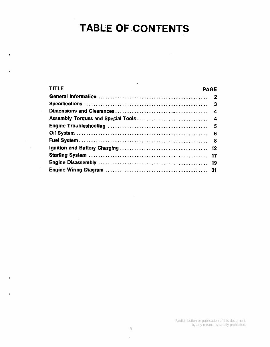
TABLE.OF CONTENTS
.
.TITLE PAGE
General Information ............................................. 2
Specifications ................................................... 3
Dimensions and Clearances ....................................... 4
Assembly Torques and Special Tools ............................. 4
Engine Troubleshooting ......................................... 5
Oil System ...................................................... 6
Fuel System ...................................................... 8
Ignition and Battery Charging .................................... 12
Starting System ................................................. 17
Engine Disassembly ............................................. 19
Engine Wiring Diagram .......................................... 31
t
1
GENERAL INFORMATION
This manual contains proper information for the
servicing and overhaul of your Onan engine. Use the
PARTS CATALOG in the rear portion of this book to
help you with disassemblyand assembly procedures.
Flywheel end of engine is considered the front. Left and right sides
are determined looking at front of engine.
If it is necessary to contact your dealer or the factory
about this engine, always supply the complete
MODEL and SPEC NUMBER as well as the SERIAL
NUMBER shown on the engine nameplate. The
engine nameplate is located on left side of blower
housing (end opposite oil filter).
Refer to the TROUBLESHOOT/NG GUIDE for
assistance in locating and correcting troubles which
may occur. If a major repair or overhaul becomes
necessary, the engine should be carefully checked
and necessary repairs made by a competent
mechanic. Maintain factory limits and clearances as
shown, replacing worn parts when necessary.
P
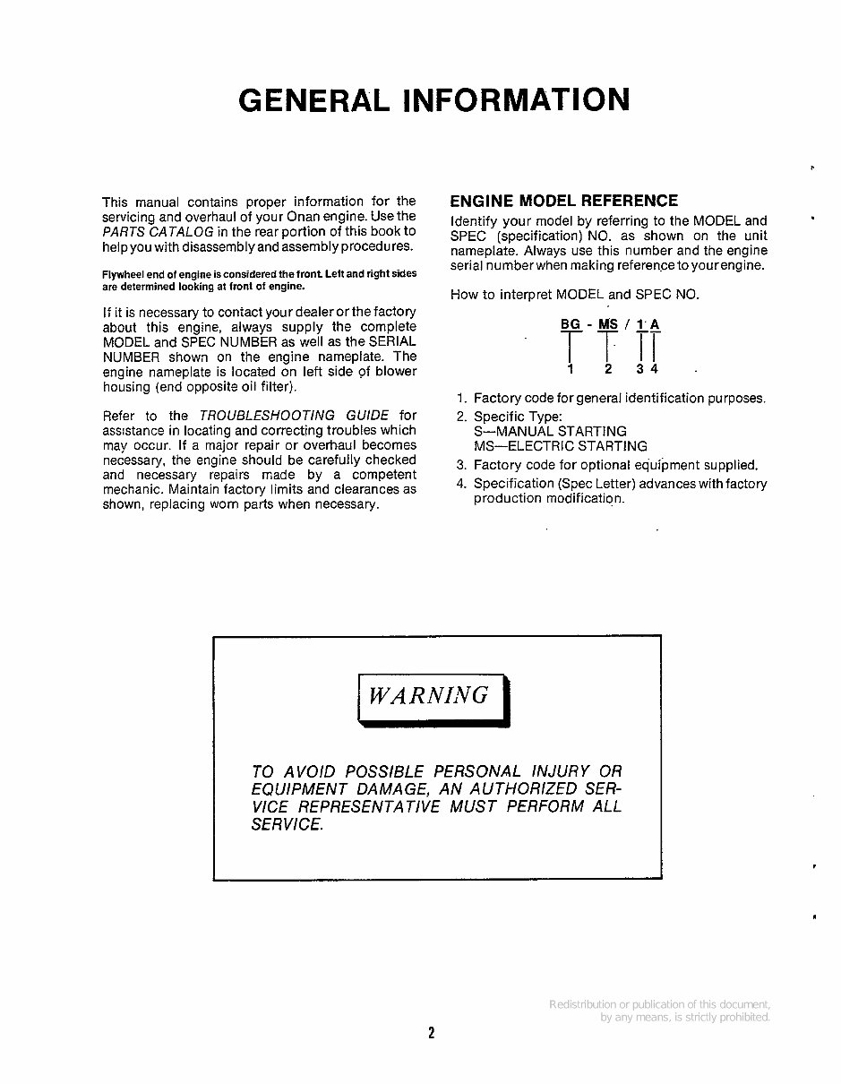
ENGINE MODEL REFERENCE
Identify your model by referring to the MODEL and
SPEC (specification) NO. as shown on the unit
nameplate. Always use this number and the engine
serial numberwhen making reference toyourengine.
How to interpret MODEL and SPEC NO.
.
Factory code for general identification purposes.
Specific Type:
S-MANUAL STARTING
MS-ELECTRIC STARTING
Factory code for optional equipment supplied.
Specification (Spec Letter) advances with factory
production modification.
I WARNING I
TO AVOlD POSSIBLE PERSONAL INJURY OR
VICE REPRESENTATIVE MUST PERFORM All
SE R VICE,
EQUIPMENT DAMAGE, AN AUTHORIZED SER-
2
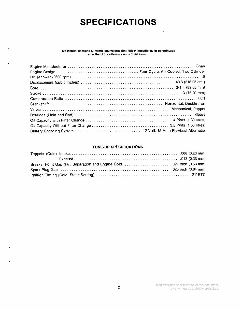
SP ECIF KAT IONS
This manual contains SI metric equivalents that follow immediately in parentheses
after the U.S. customary units of measure.
Engine Manufacturer ..................................................................... Onan
Engine Design.. ............................................ Four Cycle, Air-Cooled. Two Cylinder
i-lorsepower (3600 rpm) ...................................................................... 78
Displacement (cubic inches) ................................................... 49.8 (816.22 crn )
Bore .......................................................................... 3-114 (82.55 mm]
Stroke ............................................................................ 3 (76.20 mm)
Compression Ratio ........................................................................ 7.0:l
Crankshaft ........................... .:. ................................ Horizontal. Ductile Iron
Valves ..................................................................... Mechanical. Poppet
Bearings (Main and Rod) ................................................................ Sleeve
Oil Capacity with Filter Change .............................................. 4 Pints (1.89 Iiti-es)
011 Capacity Without Filter Change .......................................... 3.5 Pints (1.66 litresi
Battery Charging System .................................... 12 Volt. 15 Amp Flywheel Alternator
TUNE-UP SPECIFICATIONS
Tappets (Cold) Intake.. ......................................................... -008 (0-29 rnm)
Exhaust.. ....................................................... -013 (0.33 mm)
Spark Plug Gap ............................................................ .025 inch (0.64 rnm)
Ignition Timing (Cold. Static Setting) .................................................... 21'BTC
Breaker Point Gap (Full Separation and Engine Cold) ........................ .021 inch (0.53 mm)
3
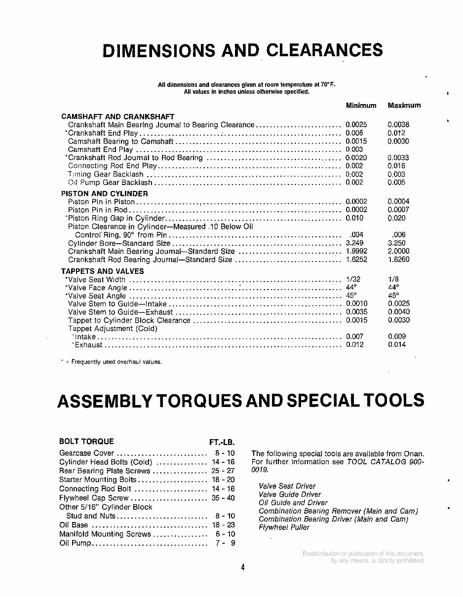
DIMENSIONS AND CLEARANCES
All dimensions and clearances given at room temperature at 7OoF .
All values in inches unless otherwise specified .
Minimum
CAMSHAFT AND CRANKSHAFT
Crankshaft Main Bearing Journal to Bearing Clearance ......................... 0.0025
*Crankshaft End Play .......................................................... 0.006
Camshaft Bearing to Camshaft ................................................ 0.0015
Camshaft End Play ........................................................... 0.003
'Crankshaft Rod Journal to Rod Bearing ....................................... 0.0020
Connecting Rod End Play ..................................................... 0.002
Timing Gear Backlash ........................................................ 0.002
01; Pump Gear Backlash ...................................................... 0.002
Piston Pin in Piston ........................................................... 0.0002
Piston Pin in Rod ............................................................. 0.0002
'Piston Ring Gap in Cylinder ................................................... 0.010
Piston Clearance in Cylinder-Measured . 10 Below Oil
Control' Ring. 90" from Pin .................................................... 004
Crankshaft Main Bearing Journal-Standard Size ............................... 1.9992
Crankshaft Rod Bearing Journal-Standard Size ............................... 1.6252
PISTON AND CYLINDER
Cylinder Bore-Standard Size ................................................. 3.249
TAPPETS AND VALVES
"Valve Seat Width ............................................................. 1/32
'Valve Face Angle ........................ .................................... 44"
'Valve Seat Angle ............................................................. 45"
Valve Stem to Guide-Intake .................................................. 0.0010
Valve Stem to Guide-Exhaust ................................................ 0.0035
Tappet to Cylinder Block Clearance ........................................... 0.0015
Tappet Adjustment (Cold)
'Intake ...................................................................... 0.007
'Exhaust .................................................................... 0.012
I
Maxim u rn
0.0038
0.01 2
0.0030
b
0.0033
0.01 6
0.003
0.005
0.0004
0.0007
0.020
.006
3.250
2.0000
1.6260
1/8
44"
45"
0.0025
0.0040
0.0030
0.009
0.014
* . Frequently used overhaul values .
ASSEMBLY TORQUES AND SPECIALTOOLS
BOLT TORQUE FT.-LB.
Gearcase Cover .......................... 8 . 10
Cylinder Head Bolts (Cold) ............... 14 . 16
Rear Bearing Plate Screws ................ 25 . 27
Starter Mounting Bolts .................... 18 . 20
Connecting Rod Bolt ..................... 14 . 16
Flywheel Cap Screw ...................... 35 . 40
Other 5/16" Cylinder Block
Stud and Nuts .......................... 8 . 10
Oil Base ................................. 18 . 23
Manifold Mounting Screws ................ 6 . 10
Oil Pump ................................. 7 . 9
The following special tools are available from Onan .
For further information see TOOL CATALOG 900-
00 19 .
P
Valve Seat Driver
Valve Guide Driver
Oil Guide and Driver
Combination Bearing Remover (Main and Cam)
Combination Bearing Driver (Main and Cam)
Flywheel Puller
4
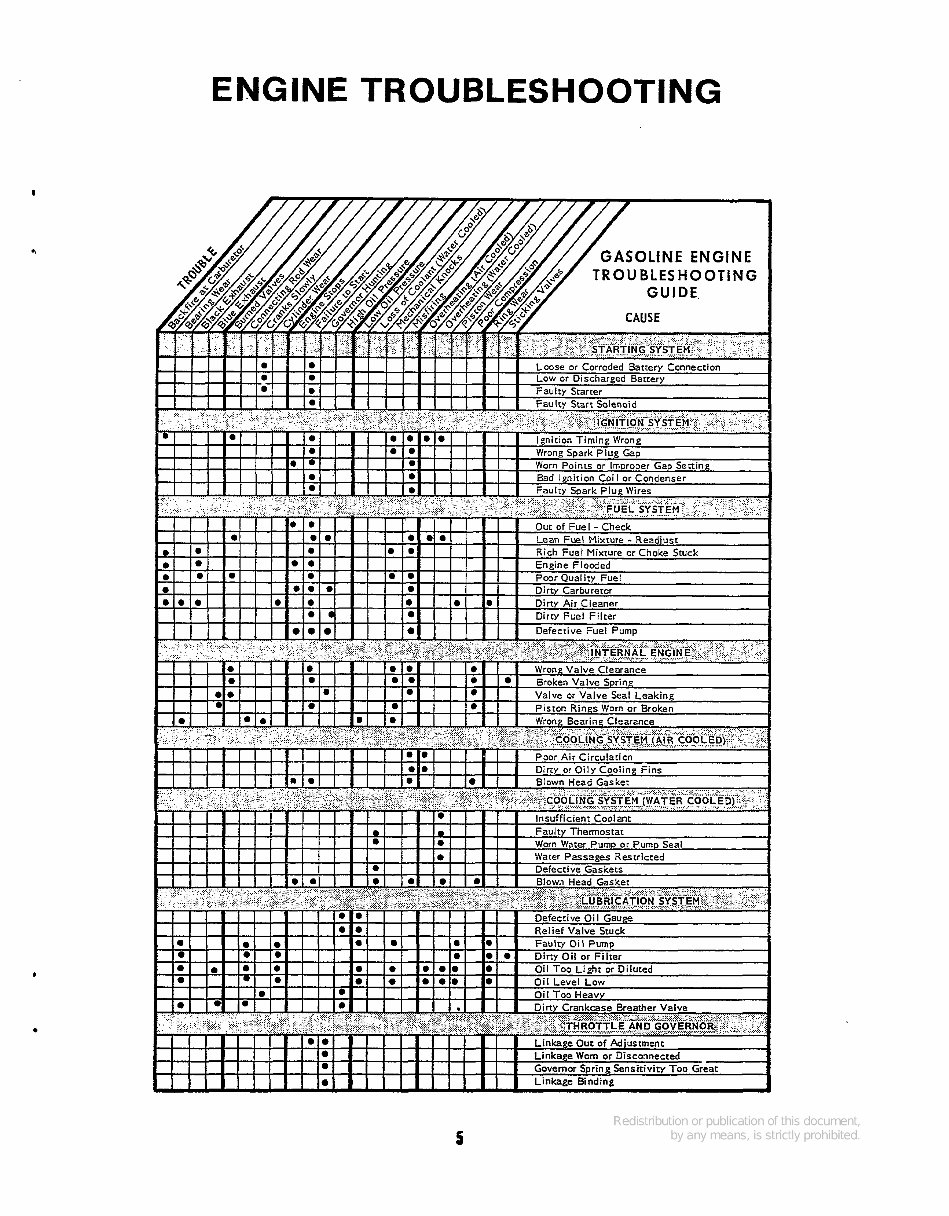
ENGINE TROUBLESHOOTING
I
5
OIL SYSTEM
Do not overfill crankcase. Do not use service
DS oil. Do not mix brands norgradesof motor
oil. Engine damage could result from mixing non-compatible oils.
I
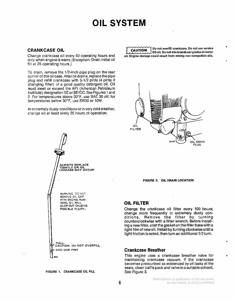
CRANKCASE OIL
Change crankcase Oil every 50 operating hours and
only when engine is warm. (Exception: Drain initial oil
fill at 25 operating hours.)
To drain, remove the 1/2-inch pipe plug on the rear
corner of the oil base. After oil drains, replacethe pipe
plug and refill crankcase with 3-1/2 pints (4 pints if
changing filter) of a good quality detergent oil. Oil
must meet or exceed the API (American Petroleum
Institute) designation SEorSEKC. SeeFigures 1 and
2. For temperatures above 30°F, use SAE 30 oil; for
temperatures below 3OoF, use 5W30 or 1OW.
In extremely dusty conditions or in very cold weather,
change oil at least every 25 hours of operation.
LWAYS REPLACE
IGHTLY OR OIL
LEAKAGE MAY OCCUR
WARY:NG: 23 Edc'!'
REMD'IE O!L CAP
NING. O!L WILL
@LOW OUT CAUSING
POSS BLE INJURY.
WH ENGIW iwr+
CAUTION- DO NOT OVERFILL
ADD ONE PINT
FIGURE 1. CRANKCASE OIL FILL
FIGURE 2 OIL DRAlN LOCATION
OIL FILTER
Change the crankcase oil filter every ?OO hours;
change more frequently in extremely dusty con-
ditions. Remove the filter by turning
counterclockwise with a filter wrench. Before install-
inganewfitter,coatthegasketon thefilterbasewith a
light film of new oil. Install.byturning clockwise until a
light friction is noted, then turn an additional 1/2 turn.
*
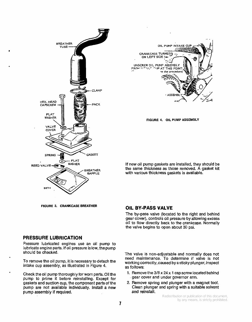
Crankcase Breather
This engine uses a crankcase breather valve for
maintaining crankcase vacuum. if the crankcase
becomes pressurized as evidenced by oil leaks at the
seals, clean baffle pack and valvein asuitablesolvent.
See Figure 3.
6
-
REED VALVE
FIGURE 3. CRANKCASE BREATHER
PRESSURE LUBRICATION
Pressure lubricated engines use an oil pump to
lubricate engine parts. If oil pressure islow,thepump
should be checked.
To remove the oil pump, it is necessary to detach the
intake cup assembly, as illustrated in Figure 4.
Check the oil pump thoroughlyfor worn parts. Oil the
pump to prime it before reinstalling. Except for
gaskets and suction cup, the component parts of the
pump are not available individually. Install a new
pump assembly if required.
b
.. .
OIL PUMP IN
CRANKCASE
ON LEFT S
UNSCREW OIL PU
FROV '?'-l<r -ItP
,T
FIGURE 4. OIL PUMP ASSEMBLY
If new oil pump gaskets are installed, they should be
the same thickness as those removed. A gasket kit
with various thickness gaskets is available.
OIL BY-PASS VALVE
The by-pass valve (located to the right and behind
gear cover), controls oil pressure by allowing excess
oil to flow directly back to the crankcase. Normally
the valve begins to open about 30 psi.
The valve is non-adjustable and normally does not
need maintenance. To determine if valve is not
working correctly,caused by asticky plunger, inspect
as follows:
1. Remove the 3/8 x 24 x 1 cap screw located behind
2. Remove spring and plunger with a magnet tool.
Clean plunger and spring with a suitable solvent
and reinstall.
, gear cover and under governor arm.
7
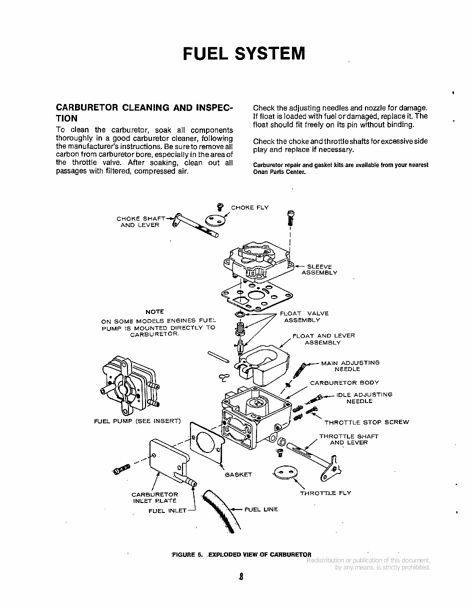
FUEL SYSTEM
CARBURETOR CLEANING AND INSPEC-
TlON
To clean the carburetor, soak all components
Check the adjusting needles and nozzle for damage.
If float is loaded with fuel or damaged, replace it. The
float should fit freely on its pin without binding.
the throttle After ;lean Out Carburetor repair and gasket kits are available from your nearest
passages with filtered, compressed air. Onan Parts Center.
CHOKE FLY
I
I
CHOKE SHAFT
AND LEVER
AT VALVE
NOTE
FLOAT AND LEVER
ON SOME MODELS ENGINES FUEL
PUMP IS MOUNTED DIRECTLY TO
CARBURETOR.
- SLEEVE
ASSEMBLY
-dd
MA 1% t.gST I N G
CARBURETOR BODY
5?
IDLE ADJUSTING
NEEDLE
THROTTLE STOP SCREW
THROTTLE SHAFT
CARB.URE1
1 \\- FUEL LINE
FUEL INLET
INLET PLATE
‘FIGURE 5. .EXPLODED VlEW OF CARBURETOR
8
You're Reading a Preview
What's Included?
Fast Download Speeds
Online & Offline Access
Access PDF Contents & Bookmarks
Full Search Facility
Print one or all pages of your manual
$28.99
$37.99
Viewed 14 Times Today


Secure transaction
What's Included?
Fast Download Speeds
Online & Offline Access
Access PDF Contents & Bookmarks
Full Search Facility
Print one or all pages of your manual
$28.99
$37.99
Get the comprehensive Onan Engines BG Parts and Service Manual for all your repair needs. This manual is compatible with all versions of Windows, Mac, and Linux, making it accessible to a wide range of users. It is available in a printable format, allowing for easy reference in the workshop or garage. With instant high-speed access, you can quickly find the information you need to get the job done efficiently. The only requirement is Adobe Reader, which is commonly available on most systems.


