

YAMAHA Generator EF6600DE Service Repair Manual
What's Included?
Fast Download Speeds
Online & Offline Access
Access PDF Contents & Bookmarks
Full Search Facility
Print one or all pages of your manual

SUPPLEMENTARY SERVICE MANUAL
EF6600DE
YG6600D
YG6600DE
7CC-28197-11 LIT-19616-01-33

HOW TO USE THIS MANUAL
PARTICULARLY IMPORTANT IN-
FORMATION
This material is distinguished by the following
notation.
Q
The Safety Alert Symbol means ATTENTION!
BECOME ALERT! YOUR SAFETY IS IN-
VOLVED!
w
Failure to follow WARNING instructions could
result in se v ere injur y or death to the machine
operator, a bystander or a person inspecting
or repairing the machine.
cC
A CAUTION indicates special precautions that
must be taken to avoid damage to the ma-
chine.
NOTE:
A NOTE provides key information to make pro-
cedures easier or clearer.
MANUAL FORMAT
The procedures in this manual are organized
in a sequential, step-by-step format. The infor-
mation has been compiled to provide the me-
chanic with an easy to read, handy reference
that contains comprehensive explanations of
all disassembly, repair, assembly, and inspec-
tion operations.
In this revised format, the condition of a faulty
component will precede an arrow symbol and
the course of action required will follow the
symbol, e.g.,
9 Bearings
Pitting/damage → Replace.
EXPLODED DIAGRAM
Each chapter provides exploded diagrams be-
fore each disassembly section for ease in
identifying the correct disassembly and as-
sembly procedures.
FOREWORD
This Supplementary Service Manual has been
prepared to introduce new service and new data
for the EF6600DE, YG6600D and YG6600DE.
For complete information on service proce-
dures, it is necessary to use this Supplementary
Service Manual together with following manual:
NOTICE
This manual was written by the Yamaha Motor
Company primarily for use by Yamaha dealers
and their qualified mechanics. It is not possible to
put an entire mechanic’s education into one man-
ual, so it is assumed that persons using this book
to perform maintenance and repairs on Yamaha
generators have a basic understanding of the
mechanical precepts and procedures inherent to
generator repair technology. Without such knowl-
edge, attempted repairs or service to this model
may render it unfit for use and/or unsafe.
Yamaha Motor Company Ltd. is continually striv-
ing to further improve all models manufactured by
Yamaha. Modifications and significant changes in
specifications or procedures will be forwarded to
all Authorized Yamaha dealers and will, where ap-
plicable, appear in future editions of this manual.
EF4600DE, EF6600DE
YG4600D, YG6600D, YG6600DE
SERVICE MANUAL:
7RH-28197-10 (310062) E. February 1996
LIT-19616-00-73
EF5200DE, EF6600DE
YG5200D, YG6600D, YG6600DE
SUPPLEMENTARY SERVICE MANUAL:
7WV-28197-10 (310125) E. August 2001
LIT -19616-00-98
EF6600DE, YG6600D, YG6600DE
SUPPLEMENTARY SERVICE MANUAL
©2008 by Yamaha Motor
Corporation, U.S.A.
1st Edition, February 2008
All rights reserved. Any reprinting or
unauthorized use without the written
permission of Yamaha Motor
Corporation, U.S.A.
is expressly prohibited.
Printed in U.S.A.
LIT-19616-01-33
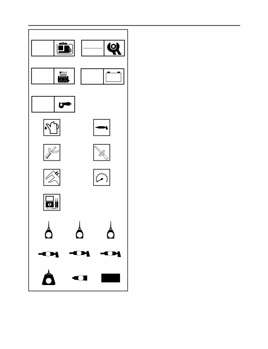
ILLUSTRATED SYMBOLS
(Refer to the illustration)
Illustrated symbols 1 through 5 are designed
as thumb tabs to indicate the chapter’s num-
ber and content.
1 General information
2 Periodic inspections and adjustments
3 Engine
4 Electrical
5 Specifications
Illustrated symbols 6 through w are used to
identify the specific tools and test equipment.
6 Filling fluid
7 Lubricant
8 Special tool
9 Tightening
0 Wear limit, clearance
q Engine speed
w Ω, V, A
Illustrated symbols e through a in the ex-
ploded diagram indicate the grades of lubri-
cant and the locations of the lubrication points.
e Apply engine oil
r Apply gear oil
t Apply molybdenum disulfide oil
y Apply wheel bearing grease
u Apply lightweight lithium-soap base grease
i Apply molybdenum disulfide grease
o Apply a locking agent (LOCTITE
®
)
p Apply Yamaha bond
a Use a new one
1 2
3 4
5
6 7
8 9
0 q
w
e r t
y u i
o p a
GEN
INFO
INSP
ADJ
ENG
ñ +
ELEC
SPEC
T
R
.
.
E G M
B
LS
M
LT
4
New

CONTENTS
GENERAL INFORMATION .............................................................................................................. 1
MACHINE IDENTIFICATION ....................................................................................................... 1
SERIAL NUMBER ................................................................................................................... 1
STARTING SERIAL NUMBER ................................................................................................ 1
PERIODIC INSPECTION AND ADJUSTMENT .............................................................................. 2
CONTROL PANEL ....................................................................................................................... 2
RECEPTACLE ........................................................................................................................ 3
FUEL TANK, CANISTER ............................................................................................................. 4
CANISTER INSTALLATION .................................................................................................... 5
MUFFLER .................................................................................................................................... 6
EXHAUST PIPE AND MUFFLER INSTALLATION .................................................................. 6
ENGINE ........................................................................................................................................... 7
CONTROL BOX ........................................................................................................................... 7
ELECTRICAL .................................................................................................................................. 8
ELECTRICAL COMPONENTS AND CIRCUIT DIAGRAM .......................................................... 8
EF6600DE .............................................................................................................................. 8
EF6600DE .............................................................................................................................. 9
YG6600D .............................................................................................................................. 10
YG6600D .............................................................................................................................. 11
YG6600DE ............................................................................................................................ 12
YG6600DE ............................................................................................................................ 13
ECONOMY IDLE SYSTEM DIAGRAM ..................................................................................... 14
GENERATOR SYSTEM ............................................................................................................. 15
TROUBLESHOOTING CHART ............................................................................................. 15
SPECIFICATIONS ......................................................................................................................... 20
GENERAL SPECIFICATIONS ................................................................................................... 20
MAINTENANCE SPECIFICATIONS .......................................................................................... 22
ENGINE ................................................................................................................................ 22
GENERATOR ........................................................................................................................ 25
ELECTRICAL ........................................................................................................................ 26
TIGHTENING TORQUE ............................................................................................................ 27
GENERAL TORQUE SPECIFICATIONS ................................................................................... 28
DEFINITION OF UNITS ............................................................................................................ 28
WIRE ROUTING DIAGRAM ...................................................................................................... 29
CONTROL BOX PANEL AND BEHIND CONTROL BOX ...................................................... 29
EF6600DE ............................................................................................................................ 29
YG6600D .............................................................................................................................. 30
YG6600DE ............................................................................................................................ 31
CANISTER ............................................................................................................................ 32
1
GEN
INFO
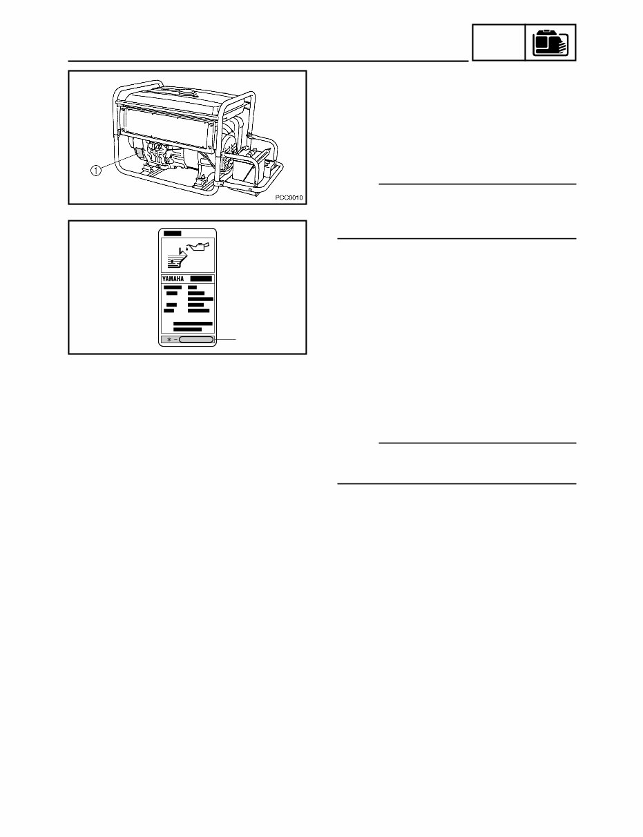
MACHINE IDENTIFICATION
PCC0020
2
GENERAL INFORMATION
MACHINE IDENTIFICATION
SERIAL NUMBER
The serial number is printed at the line 2 on a
label 1 which is affixed to the generator as
shown.
NOTE:
The first three characters of this number are
for model identification, the remaining digits
are the unit production number.
STARTING SERIAL NUMBER
EF6600DE: 7CC-1100101~
YG6600D: 7CC-1130101~
YG6600DE: 7CC-1150101~
NOTE:
Designs and specifications are subject to
change without notice.
2
INSP
ADJ
CONTROL PANEL
7
6
6
7
6
7
7
5
1
3
3
2
4
2
9
2
10
9
1
7
8
7
8
1
1
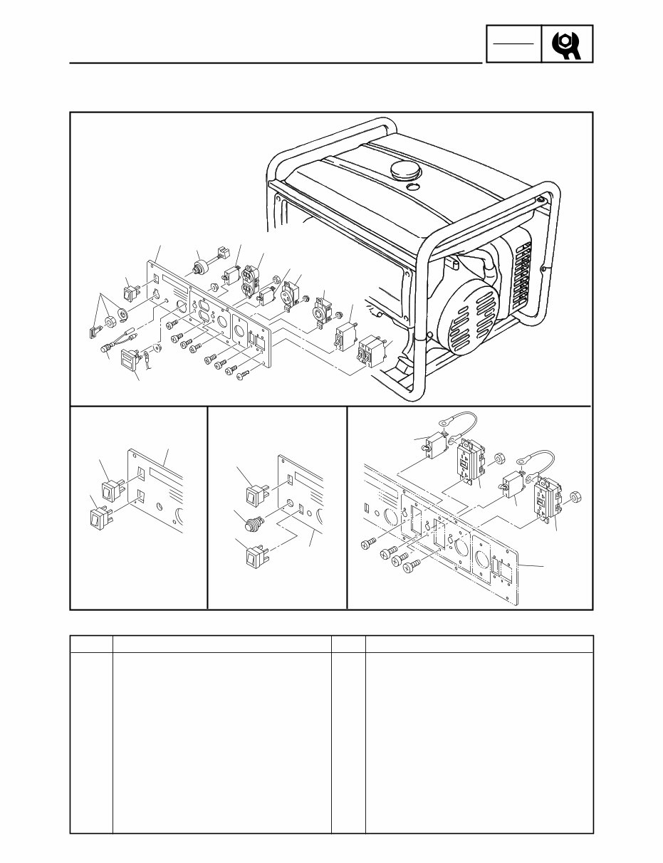
PERIODIC INSPECTION AND ADJUSTMENT
CONTROL PANEL
Order Job name/Parts name Q’ty Remarks
Control panel removal Remove the parts in the order below.
1 Panel cover 1
2 Economy idle switch 1
3 Main Switch 1
4 Oil warning light 1
5 Voltage meter 1
6 AC receptacles 2
7 AC switch(es) 4
8 G.F.C.I receptacles 2
9 Engine switch 1
10 Starter switch 1
For installation, reverse the removal
procedure.
JOB INSTRUCTION CHART
EF6600DE
YG6600D YG6600DE YG6600DE/
YG6600D
3
INSP
ADJ
RECEPTACLE
2 1
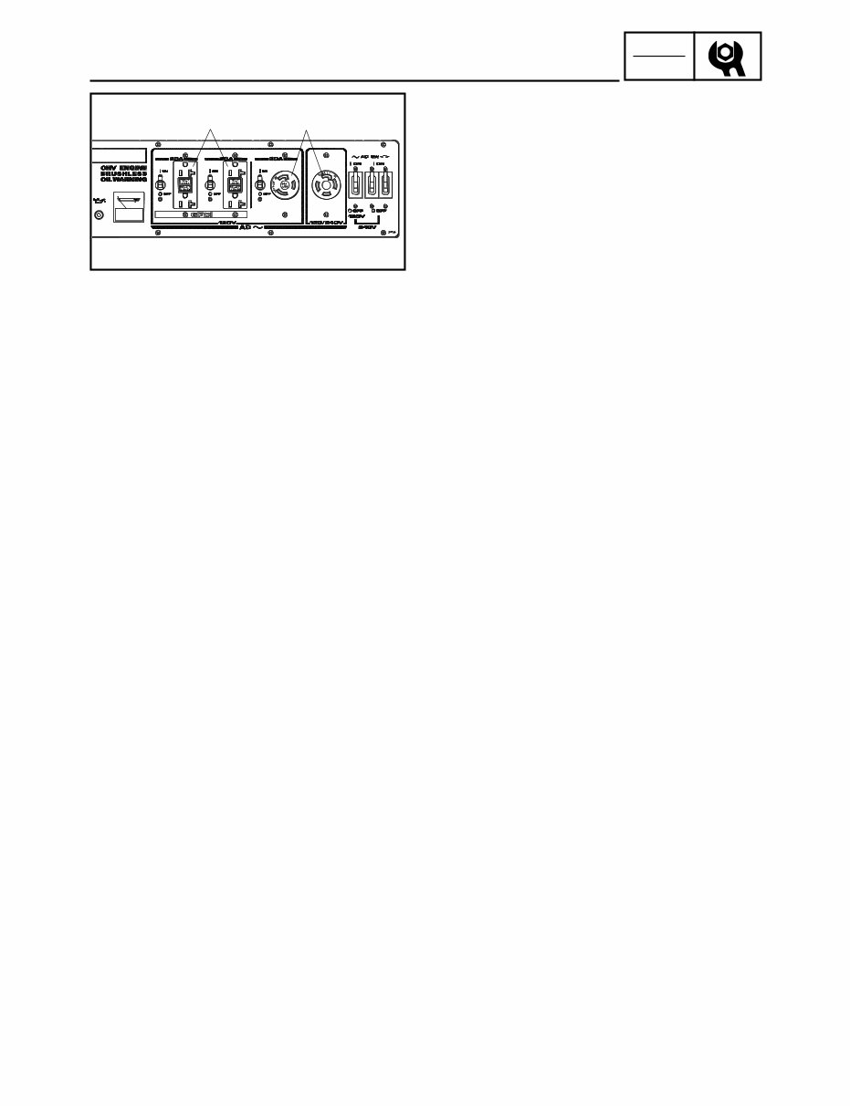
RECEPTACLE
1. Check:
9 G.F.C.I. receptacle 1
9 AC receptacle 2
Cracks/damage → Replace.
Poor connection → Correct.
1, 2 : 125V, 20 A
4
INSP
ADJ
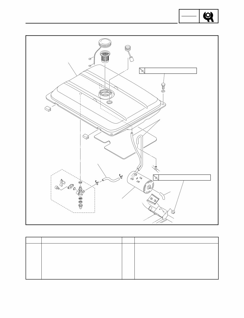
FUEL TANK, CANISTER
3
1
2
4
7 Nm (0.7 m•kg,5.1 ft•lb)
7 Nm (0.7 m•kg,5.1 ft•lb)
2
FUEL TANK, CANISTER
Order Job name/Parts name Q’ty Remarks
Air filter and fuel tank removal Remove the parts in the order below.
1 Fuel hose 1 Turn the fuel petcock to the “C” position.
2 Hose 3
3 Fuel tank 1
4 Canister 1
For installation, reverse the removal
procedure.
JOB INSTRUCTION CHART
5
INSP
ADJ
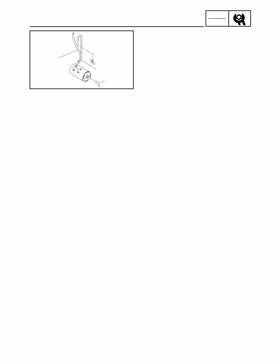
FUEL TANK, CANISTER
1
1
1
CANISTER INSTALLATION
1. Inspect:
9 Hose 1
Cracks/damage → Replace.
Poor connection → Correct.
6
ENG
MUFFLER
1
2
b
3
a
4
c
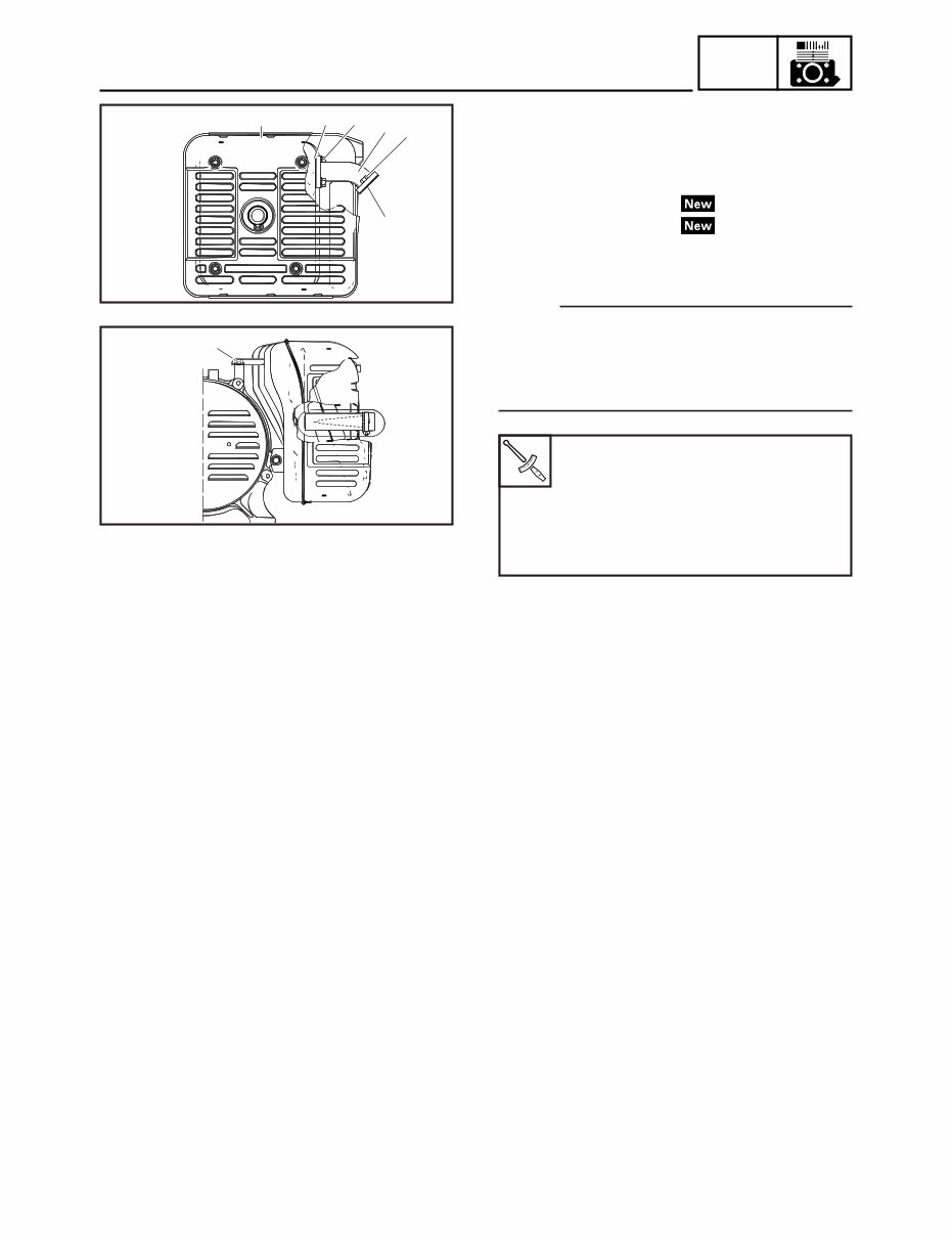
MUFFLER
EXHAUST PIPE AND MUFFLER INSTALLA-
TION
1. Install
9 Exhaust gasket 1 1
9 Exhaust gasket 2 2
9 Exhaust pipe 3
9 Muffler assembly 4
NOTE:
Tighten the nut a, nut b and bolt c until just
comes in contact with the surface, then tighten
them further to the specified torque in order of
nut a, nut b and bolt c.
Nut a
16 Nm (1.6 m · kg, 16.6 ft · lb)
Nut b
16 Nm (1.6 m · kg, 16.6 ft · lb)
Bolt c
16 Nm (1.6 m · kg, 16.6 ft · lb)
You're Reading a Preview
What's Included?
Fast Download Speeds
Online & Offline Access
Access PDF Contents & Bookmarks
Full Search Facility
Print one or all pages of your manual
$28.99
$37.99
Viewed 95 Times Today


Secure transaction
What's Included?
Fast Download Speeds
Online & Offline Access
Access PDF Contents & Bookmarks
Full Search Facility
Print one or all pages of your manual
$28.99
$37.99
The Yamaha Generator EF6600DE Service Repair Manual provides comprehensive information on the following:
- General Information
- Periodic Inspections And Adjustments
- Engine
- Electrical
- Specifications
This full version manual is available in PDF format, compatible with all versions of Windows, Mac, and Linux. It is printable and can be accessed instantly at high speed. Adobe Reader is required to view the manual.


