Yamaha EF4000DFW EF5200DE EF6600DE Generator Full Service & Repair Manual
Have a question?Ask Us
What's Included?
Fast Download Speeds
Offline Viewing
Access Contents & Bookmarks
Full Search Facility
Print one or all pages of your manual

EF4000DFW
EF4000DEFW
EF5200D
EF5200DE
EF6600D
EF6600DE
SERVICE MANUAL
7DA-F8197-10 LIT-19616-01-60

FOREWORD
This manual was written by the Yamaha Motor
Company primarily for use by Yamaha dealers
and their qualified mechanics. It is not possi-
ble to put an entire mechanic’s education into
one manual, so it is assumed that persons
using this book to perform maintenance and
repairs on Yamaha generators have a basic
understanding of the mechanical precepts and
procedures inherent to generator repair tech-
nology. Without such knowledge, attempted
repairs or service to this model may render it
unfit for use and/or unsafe.
Yamaha Motor Company Ltd. is continually
striving to further improve all models manufac-
tured by Yamaha. Modifications and significant
changes in specifications or procedures will
be forwarded to all Authorized Yamaha deal-
ers and will, where applicable, appear in
future editions of this manual.
TIP
This Service Manual contains information
regarding periodic maintenance to the
emission control system. Please read this
material carefully.
HOW TO USE THIS MANUAL
PARTICULARLY IMPORTANT
INFORMATION
Particularly important information is distin-
guished in this manual by the following nota-
tions.
This is the safety alert symbol. It is used to
alert you to potential personal injury haz-
ards. Obey all safety messages that follow
this symbol to avoid possible injury or
death.
WARNING
A WARNING indicates a hazardous situa-
tion which, if not avoided, could result in
death or serious injury.
NOTICE
A NOTICE indicates special precautions
that must be taken to avoid damage to the
machine or other property.
TIP
A TIP provides key information to make proce-
dures easier or clearer.
EF4000DFW/EF4000DEFW
EF5200D/EF5200DE
EF6600D/EF6600DE
SERVICE MANUAL
©2011 by Yamaha Motor
Corporation, U.S.A.
1st Edition, August 2011
All rights reserved. Any reprinting or
unauthorized use without the written
permission of Yamaha Motor
Corporation, U.S.A.
is expressly prohibited.
Printed in USA
LIT-19616-01-60
HOW TO USE THIS MANUAL
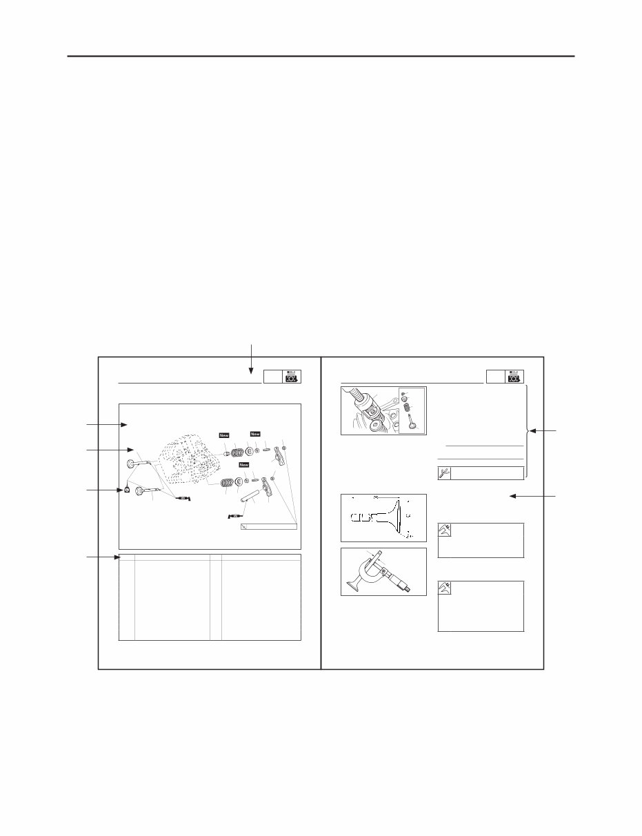
This manual is intended as a handy, easy-to-read reference book for the mechanic.
Comprehensive explanations of all installation, removal, disassembly, assembly, repair and check
procedures are laid out with the individual steps in sequential order.
9 The manual is divided into chapters and each chapter is divided into sections. The current sec-
tion title is shown at the top of each page 1.
9 Sub-section titles appear in smaller print than the section title 2.
9 To help identify parts and clarify procedure steps, there are exploded diagrams at the start of
each removal and disassembly section 3.
9 Numbers are given in the order of the jobs in the exploded diagram. A number indicates a dis-
assembly step 4.
9 Symbols indicate parts to be lubricated or replaced 5.
Refer to “ILLUSTRATED SYMBOLS”.
9 A job instruction chart accompanies the exploded diagram, providing the order of jobs, names of
parts, notes in jobs, etc. 6.
9 Jobs requiring more information (such as special tools and technical data) are described
sequentially 7.
3-33
ENG VALVE
1
4
9
8
7 Nm (0.7 m · kgf, 5.1 ft · lbf)
2 5 6
7 10
1
3
2 5
6 7
4
Order Job/Parts to remove Q’ty Remarks
Removing the valve Remove the parts in the order listed.
Cylinder head Refer to “CYLINDER HEAD COVER,
CYLINDER HEAD” on 3-29.
1 Locknut 2
2 Adjuster 2
3 Rocker arm shaft 1
4 Rocker arm 2
5 Valve cotter 2
6 Valve spring retainer 2
7 Valve spring 2
8 Exhaust valve 1
9 Intake valve 1
10 Valve stem seal 1 Intake side only.
For installation, reverse the removal pro-
cedure.
VALVE
3-34
ENG VALVE
1
2
3
4
5
SCF3180
302-001
a
REMOVING THE VALVE AND VALVE
SPRING
1. Remove:
9 Valve cotters 1
9 Valve spring retainers 2
9 Valve springs 3
9 Valves 4
9 Valve stem seal (Intake side only)
Remove the parts using the valve
spring compressor 5.
TIP
Do not compress the spring more than neces-
sary.
Valve spring compressor:
YM-01253, 90890-01253
CHECKING THE VALVE AND VALVE
SPRING
1. Measure:
9 Valve stem length a
9 Valve head diameter b
Valve stem length:
Intake: 88.1 mm (3.47 in)
Exhaust: 87.9 mm (3.46 in)
Valve head diameter:
Intake: 32.0 mm (1.26 in)
Exhaust: 27.0 mm (1.06 in)
Out of specifications → Replace.
2. Measure:
9 Valve stem diameter a
Valve stem diameter:
Standard
Intake: 5.948–5.963 mm
(0.2342–0.2348 in)
Exhaust: 5.940–5.955 mm
(0.2339–0.2344 in)
Wear limit
Intake: 5.9 mm (0.23 in)
Exhaust: 5.9 mm (0.23 in)
Out of specifications → Replace.
1
3
4
5
6
7
2
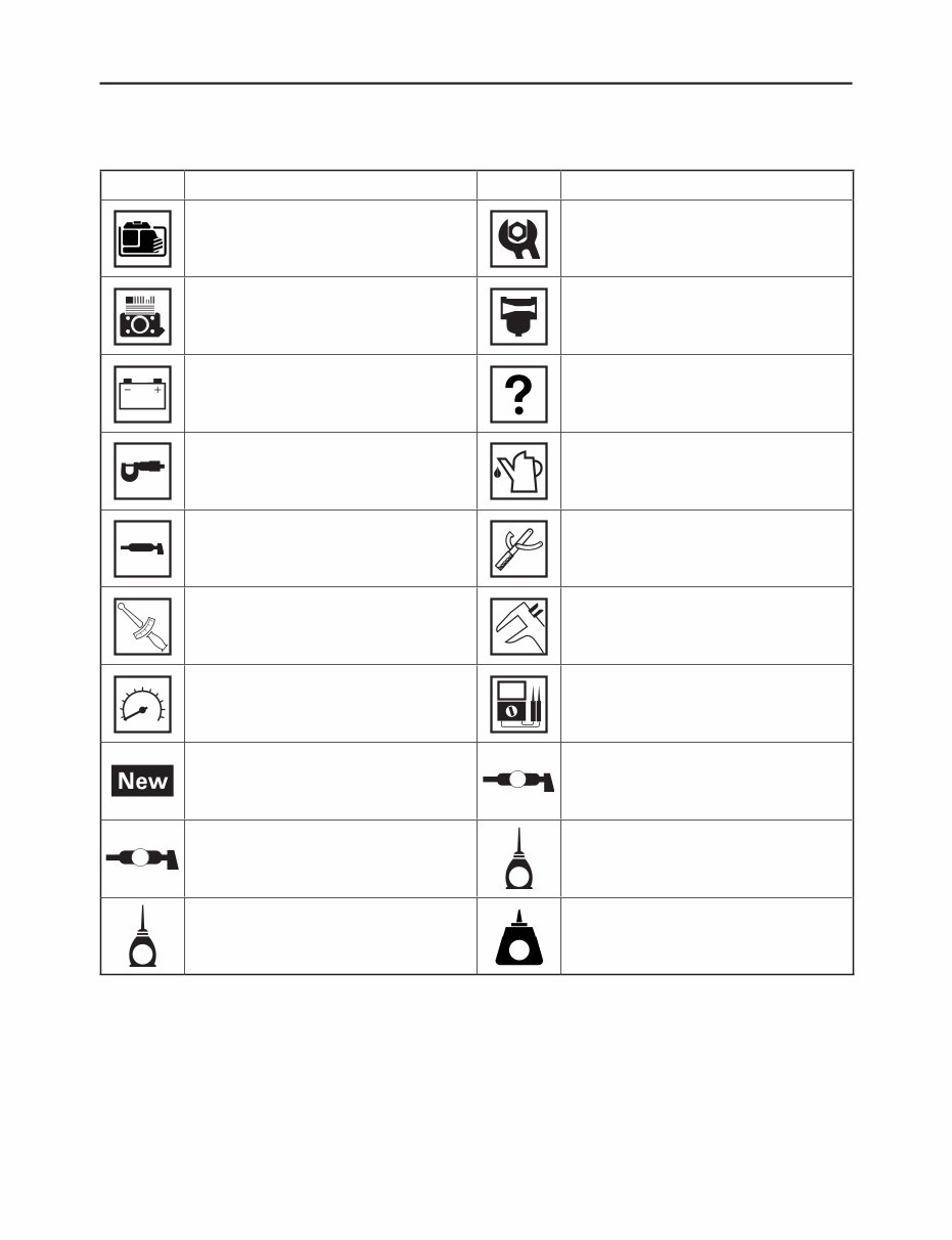
ILLUSTRATED SYMBOLS
(Refer to the illustration)
SYMBOL DEFINITION SYMBOL DEFINITION
General information
Periodic checks and
adjustments
Engine Carburetor
Electrical Troubleshooting
Specifications Filling fluid
Lubricant Special tool
T
R
.
.
Tightening torque Wear limit, clearance
Engine speed Electrical data
Replace the part with a new one.
LS
Lithium-soap base grease
M
Molybdenum disulfide grease
E
Engine oil
M
Molybdenum disulfide oil
LT
Apply locking agent (LOCTITE
®
)

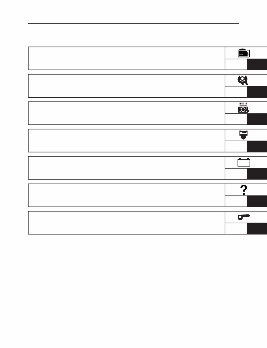
INDEX
GENERAL INFORMATION
GEN
INFO
PERIODIC CHECKS
AND ADJUSTMENTS
CHK
ADJ
ENGINE
ENG
CARBURETOR
ELECTRICAL
TROUBLESHOOTING
CARB
ELEC
TRBL
SPECIFICATIONS
SPEC
1
2
3
4
5
6
7

CHAPTER 1.
GENERAL INFORMATION
MACHINE IDENTIFICATION .....................1-1
ENGINE SERIAL NUMBER..................1-1
STARTING SERIAL NUMBER ..............1-1
IMPORTANT INFORMATION ....................1-2
PREPARATION FOR REMOVAL AND
DISASSEMBLY .....................................1-2
CAUTION ON SERVICE .......................1-2
NOTES ON SERVICE...........................1-2
ALL REPLACEMENT PARTS ...............1-3
GASKETS, OIL SEALS,
AND O-RINGS ......................................1-3
BEARINGS AND OIL SEALS ...............1-3
BASIC SERVICE INFORMATION..............1-4
ELECTRICAL SYSTEM ........................1-4
SPECIAL TOOLS AND TESTERS .............1-7
CHAPTER 2.
PERIODIC CHECKS AND
ADJUSTMENTS
INTRODUCTION ........................................2-1
MAINTENANCE INTERVALS CHART ......2-1
PERIODIC MAINTENANCE/
LUBRICATION INTERVALS ......................2-1
PERIODIC MAINTENANCE ......................2-3
SPARK PLUG .......................................2-3
FUEL LEAKAGE ...................................2-5
ENGINE OIL LEAKAGE .......................2-5
ENGINE OIL LEVEL .............................2-5
REPLACING THE ENGINE OIL ...........2-6
AIR FILTER ELEMENT .........................2-7
MUFFLER .............................................2-8
FUEL TANK FILTER..............................2-9
FUEL COCK STRAINER ....................2-10
BATTERY (EF4000DEFW/
EF5200DE/EF6600DE).......................2-10
BREATHER HOSE..............................2-11
CYLINDER HEAD
DECARBONIZATION ..........................2-11
ADJUSTING THE VALVE
CLEARANCE ......................................2-11
ADJUSTING THE ENGINE SPEED ...2-14
RECOIL STARTER .............................2-15
FITTINGS AND FASTENERS ............2-15
CHAPTER 3.
ENGINE
ENGINE INSPECTION...............................3-1
MEASURING THE COMPRESSION
PRESSURE ..........................................3-1
CONTROL BOX .........................................3-3
AIR FILTER ................................................3-5
FUEL TANK, CANISTER ...........................3-6
CHECKING THE CANISTER................3-7
MUFFLER ..................................................3-8
INSTALLING THE EXHAUST PIPE
AND MUFFLER ....................................3-9
ENGINE ....................................................3-10
RECOIL STARTER ..................................3-11
REMOVING THE RECOIL
STARTER ............................................3-12
CHECKING THE RECOIL
STARTER ............................................3-13
INSTALLING THE RECOIL
STARTER ............................................3-13
FLYWHEEL ..............................................3-15
REMOVING THE FLYWHEEL ............3-16
INSTALLING THE FLYWHEEL ...........3-17
INSTALLING THE TCI UNIT ...............3-18
GENERATOR ...........................................3-19
REMOVING THE STATOR
ASSEMBLY AND ROTOR
ASSEMBLY .........................................3-21
INSTALLING THE STATOR
ASSEMBLY AND ROTOR
ASSEMBLY .........................................3-22

GOVERNOR .............................................3-24
REMOVING THE FLYWEIGHT
SHAFT ASSEMBLY AND
GOVERNOR SHAFT ..........................3-26
DISASSEMBLING THE FLYWEIGHT
SHAFT ASSEMBLY ............................3-26
CHECKING THE FLYWEIGHT
SHAFT ASSEMBLY AND
GOVERNOR SHAFT ..........................3-27
ASSEMBLING THE FLYWEIGHT
SHAFT ASSEMBLY ............................3-27
INSTALLING THE FLYWEIGHT
SHAFT ASSEMBLY AND
GOVERNOR SHAFT ..........................3-27
ADJUSTING THE GOVERNOR..........3-28
CYLINDER HEAD COVER,
CYLINDER HEAD ....................................3-29
CHECKING THE PUSH ROD .............3-31
CHECKING THE CYLINDER
HEAD ..................................................3-31
INSTALLING THE CYLINDER
HEAD ASSEMBLY ..............................3-32
VALVE ......................................................3-33
REMOVING THE VALVE AND
VALVE SPRING ..................................3-34
CHECKING THE VALVE AND
VALVE SPRING ..................................3-34
CHECKING THE ROCKER ARM .......3-36
CHECKING THE VALVE SEAT ...........3-36
VALVE LAPPING ................................3-38
INSTALLING THE VALVE AND
VALVE SPRING ..................................3-38
PISTON, CAMSHAFT,
CRANKCASE, AND CRANKSHAFT .......3-40
REMOVING THE BALANCER
SHAFT, CAMSHAFT, AND VALVE
LIFTER................................................3-42
CHECKING THE BALANCER
SHAFT ................................................3-42
CHECKING THE CAMSHAFT ............3-43
CHECKING THE VALVE LIFTER........3-44
INSTALLING THE VALVE LIFTER,
BALANCER SHAFT, AND
CAMSHAFT ........................................3-44
CHECKING THE CRANKCASE
COVER ...............................................3-44
INSTALLING THE CRANKCASE
COVER ...............................................3-45
CHECKING THE CYLINDER..............3-45
CHECKING THE CRANKCASE .........3-46
CHECKING THE PISTON AND
PISTON PIN........................................3-47
CHECKING THE PISTON RING ........3-48
CHECKING THE CRANKSHAFT .......3-49
CHECKING THE CONNECTING
ROD OIL CLEARANCE ......................3-51
INSTALLING THE PISTON AND
PISTON RING.....................................3-52
INSTALLING THE CRANKSHAFT ......3-53
CHAPTER 4.
CARBURETOR
REMOVING THE CARBURETOR ..............4-1
DISASSEMBLING THE CARBURETOR ...4-3
EF4000DFW/EF5200D/EF6600D .........4-3
EF4000DEFW/EF5200DE/
EF6600DE ............................................4-5
CHECKING THE CARBURETOR .........4-7
CHECKING THE AUTO CHOKE
(EF4000DEFW/EF5200DE/
EF6600DE) ...........................................4-8
CHECKING THE FUEL CUT
SOLENOID VALVE................................4-9
CHAPTER 5.
ELECTRICAL
ELECTRICAL COMPONENTS ..................5-1
CIRCUIT DIAGRAM ...................................5-2
EF4000DFW .........................................5-2
EF4000DEFW .......................................5-3
EF5200D/EF6600D...............................5-4
EF5200DE/EF6600DE ..........................5-5
CONTROL PANEL .....................................5-6
EF4000DFW/EF4000DEFW .................5-6
EF5200D/EF5200DE/EF6600D/
EF6600DE ............................................5-8
BATTERY
(EF4000DEFW/EF5200DE/EF6600DE) ...5-10
CHECKING THE BATTERY ................5-10

FUSE
(EF4000DEFW/EF5200DE/EF6600DE) ...5-12
CHECKING THE FUSE ......................5-12
SWITCHES...............................................5-14
CHECKING THE SWITCH
CONTINUITY .....................................5-14
IGNITION SYSTEM..................................5-15
TROUBLESHOOTING CHART...........5-15
ELECTRIC STARTING SYSTEM
(EF4000DEFW/EF5200DE/EF6600DE) ...5-21
TROUBLESHOOTING CHART...........5-21
REMOVING THE STARTER
MOTOR ...............................................5-23
DISASSEMBLING THE STARTER
MOTOR ...............................................5-24
CHECKING THE ARMATURE COIL...5-25
CHECKING THE BRUSH ...................5-26
CHECKING THE MAGNETIC
SWITCH ..............................................5-26
CHARGING SYSTEM
(EF4000DEFW/EF5200DE/EF6600DE) ...5-27
TROUBLESHOOTING CHART...........5-27
GENERATOR SYSTEM ...........................5-29
TROUBLESHOOTING CHART...........5-29
ECONOMY CONTROL SYSTEM ............5-40
ECONOMY CONTROL SYSTEM
DIAGRAM ...........................................5-40
TROUBLESHOOTING CHART...........5-41
CHAPTER 6.
TROUBLESHOOTING
ENGINE ......................................................6-1
CHAPTER 7.
SPECIFICATIONS
GENERAL SPECIFICATIONS ...................7-1
MAINTENANCE SPECIFICATIONS ..........7-4
ENGINE ................................................7-4
ELECTRICAL ........................................7-7
GENERATOR ........................................7-8
TIGHTENING TORQUES .........................7-10
GENERAL TORQUE
SPECIFICATIONS....................................7-12
LUBRICATION POINTS AND TYPE OF
LUBRICANTS ..........................................7-13
WIRE ROUTING DIAGRAM ....................7-14
CONTROL PANEL AND CONTROL
BOX (EF4000DFW) ............................7-14
CONTROL PANEL AND CONTROL
BOX (EF4000DEFW) ..........................7-16
CONTROL PANEL AND CONTROL
BOX (EF5200D/EF6600D) ..................7-18
CONTROL PANEL AND CONTROL
BOX (EF5200DE/EF6600DE) .............7-20
BACK SIDE AND LEFT SIDE VIEW...7-22
UPPER SIDE VIEW ............................7-23
ENGINE ..............................................7-25
GENERATOR ......................................7-26
You're Reading a Preview
What's Included?
Fast Download Speeds
Offline Viewing
Access Contents & Bookmarks
Full Search Facility
Print one or all pages of your manual
$39.99
Viewed 22 Times Today


Secure transaction
What's Included?
Fast Download Speeds
Offline Viewing
Access Contents & Bookmarks
Full Search Facility
Print one or all pages of your manual
$39.99
- This is a complete factory service repair workshop manual for Yamaha EF4000DFW, EF5200DE, and EF6600DE generators.
- It is available for instant access on your computer, tablet, or smartphone.
- The manual covers all repairs, servicing, and troubleshooting procedures with detailed photos and diagrams.
- Professional mechanics and technicians use this type of manual, which contains step-by-step instructions and highly detailed exploded diagrams and pictures.
- You have the option to print out a single page or the entire manual.
- This manual can be used on multiple computers without any limitations or trial periods.
- There is no expiration date or renewal fee for this full manual, and it can be used for life.
- It is fully compatible with all Windows and MAC computers.
Thanks for considering this item. Please click on the button for more information.