


SUPPLEMENTARY SERVICE MANUAL
EF3000iSE
EF3000iSEB
LIT-19616-01-20 7CH-28197-10
310144

FOREWORD
This Supplementary Service Manual has been
prepared to introduce new service and new
data for the EF3000iSE and EF3000iSEB. For
complete information on service procedures, it
is necessary to use this Supplementary Ser-
vice Manual together with following manual:
NOTICE
This manual was written by the Yamaha Motor
Company primarily for use by Yamaha dealers
and their qualified mechanics. It is not possible
to put an entire mechanic’s education into one
manual, so it is assumed that persons using
this book to perform maintenance and repairs
on Yamaha generators have a basic under-
standing of the mechanical precepts and pro-
cedures inherent to generator repair
technology. Without such knowledge,
attempted repairs or service to this model may
render it unfit for use and/or unsafe.
Yamaha Motor Company Ltd. is continually
striving to further improve all models manufac-
tured by Yamaha. Modifications and significant
changes in specifications or procedures will be
forwarded to all Authorized Yamaha dealers
and will, where applicable, appear in future
editions of this manual.
HOW TO USE THIS MANUAL
PARTICULARLY IMPORTANT
INFORMATION
This material is distinguished by the following
notation.
The Safety Alert Symbol means ATTENTION!
BECOME ALERT! YOUR SAFETY IS
INVOLVED!
Failure to follow WARNING instructions could
result in severe injury or death to the machine
operator, a bystander, or a person inspecting
or repairing the machine.
A CAUTION indicates special precautions that
must be taken to avoid damage to the
machine.
NOTE:
A NOTE provides key information to make pro-
cedures easier or clearer.
MANUAL FORMAT
The procedures in this manual are organized
in a sequential, step-by-step format. The infor-
mation has been compiled to provide the
mechanic with an easy to read, handy refer-
ence that contains comprehensive explana-
tions of all disassembly, repair, assembly, and
inspection operations.
In this revised format, the condition of a faulty
component will precede an arrow symbol and
the course of action required will follow the
symbol, e.g.,
• Bearings
Pitting/damage → Replace.
EXPLODED DIAGRAM
Each chapter provides exploded diagrams
before each disassembly section for ease in
identifying the correct disassembly and
assembly procedures.
EF3000iSE/EF3000iSEB
SERVICE MANUAL:
7WL-28197-10 (310133) E. October 2002
LIT-19616-01-03
EF3000iSE/EF3000iSEB
SUPPLEMENTARY SERVICE MANUAL
©2004 by Yamaha Motor
Corporation, U.S.A.
1st Edition, July 2004
All rights reserved. Any reprinting or
unauthorized use without the written
permission of Yamaha Motor
Corporation, U.S.A.
is expressly prohibited.
Printed in U.S.A.
LIT-19616-01-20
WARNING
CAUTION:
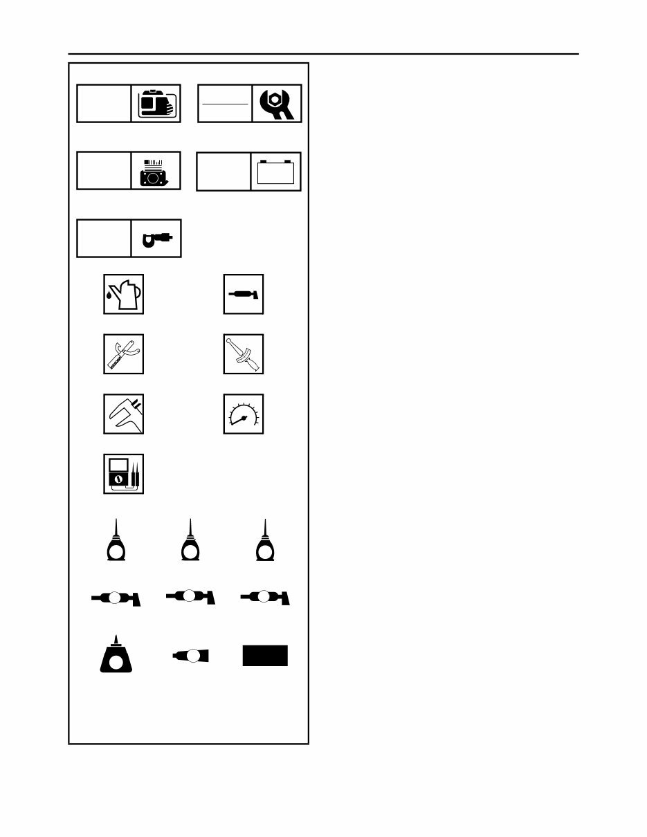
ILLUSTRATED SYMBOLS
(Refer to the illustration)
Illustrated symbols 1 through 5 are designed
as thumb tabs to indicate the chapter’s number
and content.
1 General information
2 Periodic inspections and adjustments
3 Engine
4 Electrical
5 Specifications
Illustrated symbols 6 through B are used to
identify the specific tools and test equipment.
6 Filling fluid
7 Lubricant
8 Special tool
9 Tightening
0 Wear limit, clearance
A Engine speed
B Ω, V, A
Illustrated symbols C through K in the
exploded diagram indicate the grades of lubri-
cant and the locations of the lubrication points.
C Apply engine oil
D Apply gear oil
E Apply molybdenum disulfide oil
F Apply wheel bearing grease
G Apply lightweight lithium-soap base grease
H Apply molybdenum disulfide grease
I Apply a locking agent (LOCTITE
®
)
J Apply Yamaha bond
K Use a new one
1 2
3 4
5
6 7
8 9
0 A
B
C D E
F G H
I J K
GEN
INFO
INSP
ADJ
ENG
– +
ELEC
SPEC
T
R
.
.
E G M
B
LS
M
LT
4
New

CONTENTS
GENERAL INFORMATION .......................... 1
MACHINE IDENTIFICATION .................. 1
SERIAL NUMBER.............................. 1
STARTING SERIAL NUMBER .......... 1
SPECIFICATIONS ........................................ 3
GENERAL SPECIFICATIONS ................ 3
MAINTENANCE SPECIFICATIONS ....... 5
ENGINE ............................................. 5
GENERATOR AND ELECTRICAL .... 8
LUBRICATION POINTS
AND LUBRICANT TYPES ....................... 9
TIGHTENING TORQUE ........................ 10
GENERAL TORQUE
SPECIFICATIONS................................. 12
DEFINITION OF UNITS ........................ 12
WIRE ROUTING DIAGRAM .................. 13
CONTROL PANEL........................... 13
BEHIND CONTROL PANEL
AND CONTROL BOX INTERIOR .... 13
BEHIND CONTROL BOX ................ 13
ENGINE AND GENERATOR
(EF3000iSE) .................................... 14
ENGINE AND GENERATOR
(EF3000iSEB) .................................. 17
1
GEN
INFO
MACHINE IDENTIFICATION
GENERAL INFORMATION
MACHINE IDENTIFICATION
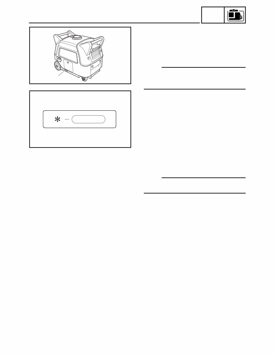
SERIAL NUMBER
The serial number is printed on a label 1
which is affixed to the generator as shown.
NOTE:
The first three characters of this number are
for model identification, the remaining digits
are the unit production number.
1
PCH0060
SWL1020J
STARTING SERIAL NUMBER
EF3000iSE: 7CH-230101 ~
EF3000iSEB: 7CH-200101 ~
NOTE:
Designs and specifications are subject to
change without notice.

2
GEN
INFO
MACHINE IDENTIFICATION
3
SPEC
SPECIFICATIONS
GENERAL SPECIFICATIONS
Unit EF3000iSE/EF3000iSEB
Model code number 7CH2
Dimensions:
Overall length mm (in) 680 (26.8)
Overall width mm (in) 445 (17.5)
Overall height mm (in) 555 (21.9)
Dry weight kg (lb) 67 (147.7) (EF3000iSE)
69 (152.1) (EF3000iSEB)
Engine:
Engine type 4-stroke, OHV, forced air cooled
Cylinder arrangement 1
Displacement L (cm
3
) 0.171 (171)
Bore × Stroke mm (in) 66.0 × 50.0 (2.60 × 1.97)
Compression ratio 8.5:1
Standard compression pressure
kPa (kg/cm
2
, psi) 400 ~ 600 (4 ~ 6, 57 ~ 85)
Rated output 60 Hz · kW (PS)/3,800 r/min 3.5 (4.7)
Operating hours 60 Hz · Hrs
1/4 load (economy switch is on) 20.5
Rated load (economy switch is on) 8.0
Fuel Unleaded regular gasoline
Fuel tank capacity L (Imp gal, US gal) 13.0 (2.86, 3.43)
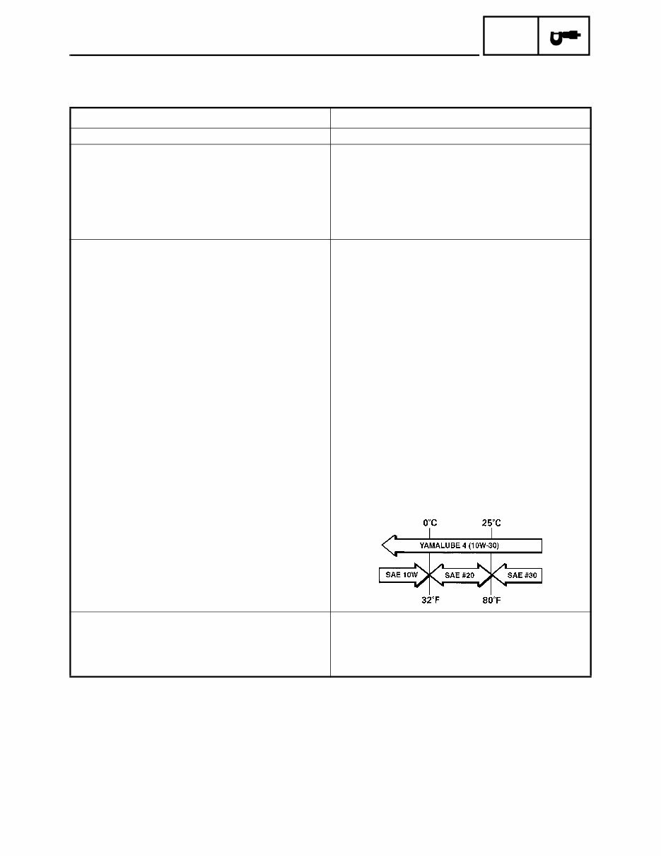
Engine oil quantity L (Imp qt, US qt) 0.6 (0.53, 0.63)
Engine oil grade 4-stroke engine oil API service classification
SE or SF, if not available, SD
Electrical:
Ignition system TCI
Spark plug type BPR4ES (NGK)
Gap mm (in) 0.7 ~ 0.8 (0.028 ~ 0.031)
GENERAL SPECIFICATIONS
4
SPEC
Generator:
Type Multi pole rotating field magnet
Initial excitation Permanent magnet
Driving method Direct connection
Rated power factor 1.0
Frequency variation
Instantaneous Less than 1%
Settling Less than 0.1%
Settling time Less than 1 sec
Voltage fluctuation
Instantaneous Less than 20%
Settling Less than 3%
Settling time Less than 2 sec
AC output
Rated voltage V 120
Frequency Hz 60
Rated output kVA 2.8
Rated current A 23.3
DC output
Rated voltage V 12
Rated current A 12
Safety device type AC Electronic no fuse breaker
DC Circuit breaker (No fuse breaker)
Engine speed (no load) r/min 3,800
Rated engine speed r/min 3,800
Economy engine speed (no load) r/min 2,800 ± 50
Voltage regulation Voltage feed back system
Voltage stability Within ± 4%
Frequency stability Hz Within ± 1.0
Rotating speed control Throttle motor control type
Wave distortion ratio Less than 2.5%
Number of phase
AC output (main coil) Three phase
DC output (sub coil) Single phase
Insulation resistance MΩ Over 10
Insulation type B type
Receptacle AC 20 A (Duple) × 1, 30 A × 1
DC 12 A × 1
Unit EF3000iSE/EF3000iSEB
GENERAL SPECIFICATIONS
5
SPEC
MAINTENANCE SPECIFICATIONS
ENGINE
Unit EF3000iSE/EF3000iSEB
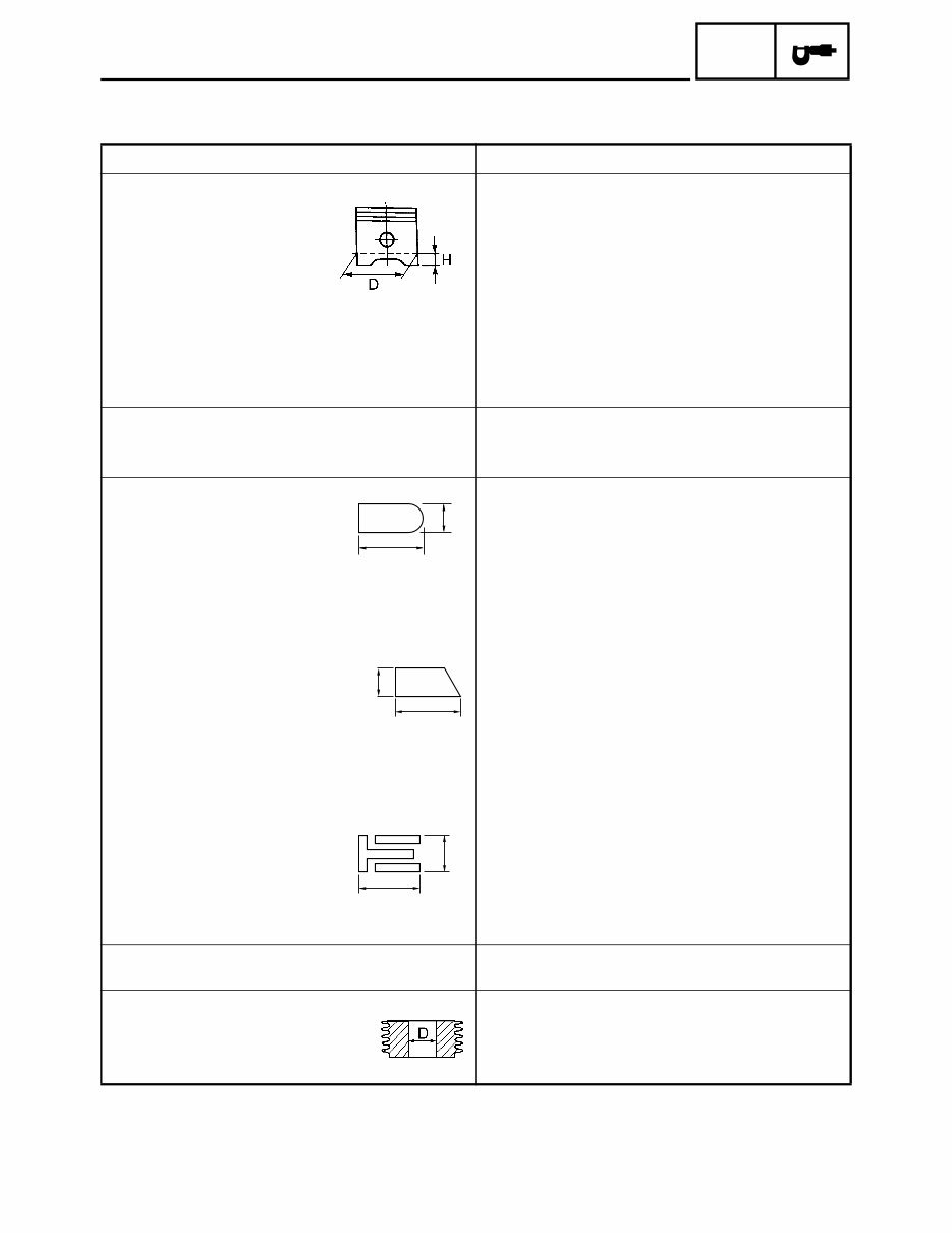
Piston: mm (in)
Piston clearance 0.015 ~ 0.040 (0.00059 ~ 0.00157)
<Limit> 0.15 (0.00591)
Piston skirt “D” 65.975 ~ 65.990 (2.5974 ~ 2.5980)
<Limit> 65.9 (2.5945)
Measuring point “H” 10.0 (0.4)
Oversize 1st 66.225 ~ 66.240 (2.6073 ~ 2.6079)
2nd 66.475 ~ 66.490 (2.6171 ~ 2.6177)
Piston pin hole inside diameter 16.002 ~ 16.013 (0.6300 ~ 0.6304)
<Limit> 16.043 (0.6316)
Piston pin: mm (in)
Piston pin diameter 15.995 ~ 16.000 (0.6297 ~ 0.6299)
<Limit> 15.975 (0.6289)
Piston ring: mm (in)
Top ring
Type Barrel face
Dimensions “B × T” 1.5 × 2.7 (0.0591 × 0.1063)
End gap 0.20 ~ 0.40 (0.0079 ~ 0.0157)
<Limit> 0.65 (0.0256)
Side clearance 0.04 ~ 0.08 (0.0016 ~ 0.0031)
<Limit> 0.13 (0.0051)
2nd ring
Type Taper
Dimensions “B × T” 1.5 × 2.7 (0.0591 × 0.1063)
End gap 0.20 ~ 0.40 (0.0079 ~ 0.0157)
<Limit> 0.75 (0.0295)
Side clearance 0.02 ~ 0.06 (0.0008 ~ 0.0024)
<Limit> 0.12 (0.0047)
Oil ring
Type Solid
Dimensions “B × T” 2.5 × 2.8 (0.0984 × 0.1102)
End gap 0.20 ~ 0.70 (0.0079 ~ 0.0276)
<Limit> 0.9 (0.0354)
Cylinder head: mm (in)
Warpage limit 0.05 (0.0020)
Cylinder: mm (in)
Inside diameter “D” 66.005 ~ 66.015 (2.5986 ~ 2.5990)
<Limit> 66.020 (2.5992)
Taper limit 0.05 (0.0020)
T
B
B
T
B
T
MAINTENANCE SPECIFICATIONS
You're Reading a Preview
What's Included?
 Lifetime Access
Fast Download Speeds
Online & Offline Access
Access PDF Contents & Bookmarks
Full Search Facility
Print one or all pages of your manual
$39.99
Yamaha Generator Inverter EF3000iseb&c SpplemService manual
Viewed 79 Times Today

What's Included?
Lifetime Access
Fast Download Speeds
Online & Offline Access
Access PDF Contents & Bookmarks
Full Search Facility
Print one or all pages of your manual
$39.99

Secure transaction
What's Included?
Lifetime Access
Fast Download Speeds
Online & Offline Access
Access PDF Contents & Bookmarks
Full Search Facility
Print one or all pages of your manual
Description
A comprehensive General Information section provides at-a-glance service data for experienced technicians, eliminating the need to review specific sections for specifications and tolerances. Less experienced technicians benefit from section information that starts with an exploded view of the system, followed by relevant service data, special tools information, and step-by-step repair instructions, including disassembly, inspection, testing/troubleshooting, repair, assembly, and adjustment.
- EASY TO FILE AND VIEW
- ITS ALWAYS IN NEW CONDITION
- EASIER TO FIND PAGES AND JUST PRINT WHAT YOU NEED
- EASIER TO VIEW WITH THE ZOOM IN / OUT ON . S FILES
WHERE ELSE BUT IN THIS FACTORY MANUAL WILL YOU FIND THE INFO YOU NEED?
File Format:
- Compatible: All Versions of Windows & Mac & Linux
- Printable: Yes
- Downloadable: Instant High Speed
- Requirements: Adobe Reader
Easy to understand/Easy to navigate


