

Yamaha Generator EF2000is Service Repair Manual
What's Included?
Fast Download Speeds
Online & Offline Access
Access PDF Contents & Bookmarks
Full Search Facility
Print one or all pages of your manual

SERVICE MANUAL
EF2000iS
LIT-19616-01-53
7DK-28197-10

FOREWORD
This manual was written by the Yamaha Motor
Company primarily for use by Yamaha dealers
and their qualified mechanics. It is not possible
to put an entire mechanic’s education into one
manual, so it is assumed that persons using
this book to perform maintenance and repairs
on Yamaha generators have a basic under-
standing of the mechanical precepts and pro-
cedures inherent to generator repair
technology. Without such knowledge,
attempted repairs or service to this model may
render it unfit for use and/or unsafe.
Yamaha Motor Company Ltd. is continually
striving to further improve all models manufac-
tured by Yamaha. Modifications and significant
changes in specifications or procedures will be
forwarded to all Authorized Yamaha dealers
and will, where applicable, appear in future
editions of this manual.
TIP
This Service Manual contains information
regarding periodic maintenance to the emis-
sion control system. Please read this material
carefully.
HOW TO USE THIS MANUAL
PARTICULARLY IMPORTANT
INFORMATION
Particularly important information is distin-
guished in this manual by the following
notations.
This is the safety alert symbol. It is used to
alert you to potential personal injury haz-
ards. Obey all safety messages that follow
this symbol to avoid possible injury or
death.
A WARNING indicates a hazardous situa-
tion which, if not avoided, could result in
death or serious injury.
A NOTICE indicates special precautions
that must be taken to avoid damage to the
machine or other property.
TIP
A TIP provides key information to make
procedures easier or clearer.
MANUAL FORMAT
The procedures in this manual are organized
in a sequential, step-by-step format. The infor-
mation has been compiled to provide the
mechanic with an easy to read, handy refer-
ence that contains comprehensive explana-
tions of all disassembly, repair, assembly, and
inspection operations.
In this revised format, the condition of a faulty
component will precede an arrow symbol and
the course of action required will follow the
symbol, e.g.,
9 Bearings
Pitting/damage → Replace.
EXPLODED DIAGRAM
Each chapter provides exploded diagrams
before each disassembly section for ease in
identifying the correct disassembly and
assembly procedures.
NOTICE
WARNING
EF2000iS
SERVICE MANUAL
©2009 by Yamaha Motor
Corporation, U.S.A.
1st Edition, March 2009
All rights reserved. Any reprinting or
unauthorized use without the written
permission of Yamaha Motor
Corporation, U.S.A.
is expressly prohibited.
Printed in USA
LIT-19616-01-53
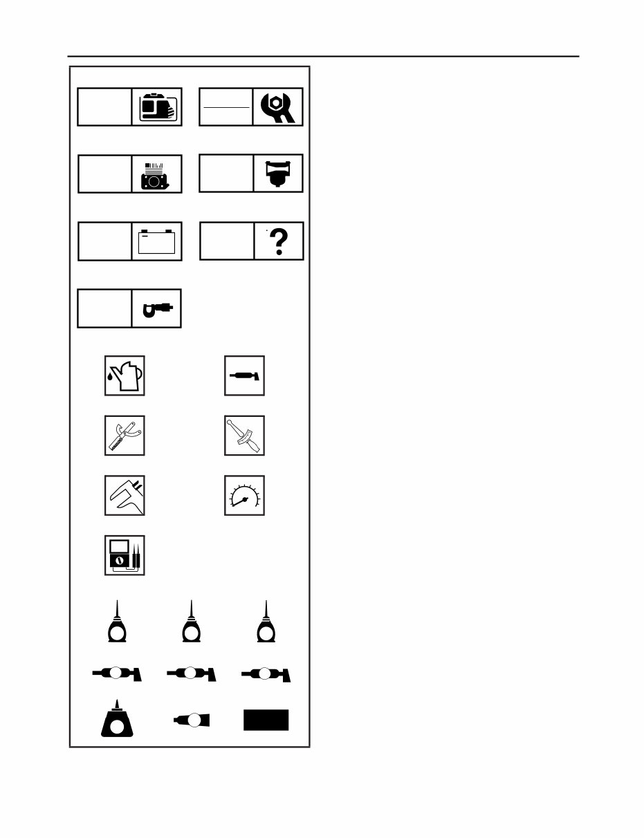
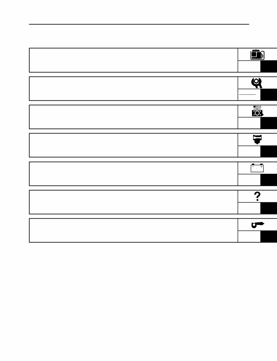
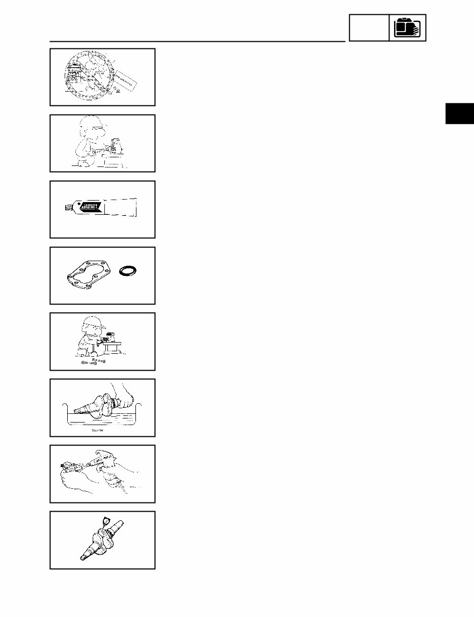
ILLUSTRATED SYMBOLS
(Refer to the illustration)
Illustrated symbols 1 through 7 are designed
as thumb tabs to indicate the chapter’s number
and content.
1 General information
2 Periodic inspections and adjustments
3 Engine
4 Carburetor
5 Electrical
6 Trouble shooting
7 Specifications
Illustrated symbols 8 through r are used to
identify the specific tools and test equipment.
8 Filling fluid
9 Lubricant
0 Special tool
q Tightening
w Wear limit, clearance
e Engine speed
r Electrical data
Illustrated symbols t through d in the
exploded diagram indicate the grades of lubri-
cant and the locations of the lubrication points.
t Apply engine oil
y Apply gear oil
u Apply molybdenum disulfide oil
i Apply wheel bearing grease
o Apply lightweight lithium-soap base grease
p Apply molybdenum disulfide grease
a Apply a locking agent (LOCTITE
®
)
s Apply Yamaha bond
d Use a new one
GEN
INFO
INSP
ADJ
ENG
ELEC
T
R
.
.
E G M
B LS
M
LT
4
New
1 2
3 4
5 6
CARB
SPEC
7
TRBL
+
8 9
0 q
w e
r
t
y u
i o p
a s d
INDEX
GENERAL INFORMATION
GEN
INFO
PERIODIC INSPECTIONS
AND ADJUSTMENTS
INSP
ADJ
ENGINE
ENG
CARBURETOR
CARB
ELECTRICAL
ELEC
TROUBLESHOOTING
TRBL
SPECIFICATIONS
SPEC
1
2
3
4
5
6
7

CHAPTER 1.
GENERAL INFORMATION
MACHINE IDENTIFICATION ................... 1-1
SERIAL NUMBER .............................. 1-1
STARTING SERIAL NUMBER ............ 1-1
IMPORTANT INFORMATION
PREPARATION FOR REMOVAL AND
DISASSEMBLY CAUTION ON
SERVICE ............................................ 1-2
NOTES ON SERVICE ........................ 1-2
ALL REPLACEMENT PARTS ............. 1-3
GASKETS, OIL SEALS, AND
O-RINGS ............................................ 1-3
BEARINGS AND OIL SEALS ............. 1-3
SPECIAL TOOLS AND TESTERS ........... 1-4
CHAPTER 2.
PERIODIC INSPECTIONS AND
ADJUSTMENTS
INTRODUCTION ...................................... 2-1
MAINTENANCE INTERVALS CHART .... 2-1
PERIODIC MAINTENANCE/
LUBRICATION INTERVALS .................... 2-1
COVERS AND FUEL TANK ..................... 2-3
COVERS ..............................................2-3
COVERS AND FUEL TANK .................2-4
COVERS AND FUEL TANK
REMOVAL ........................................... 2-5
COVERS AND FUEL TANK
INSTALLATION ................................... 2-6
ENGINE .................................................... 2-7
ENGINE OIL LEAKAGE
CHECKING ......................................... 2-7
OIL LEVEL CHECKING ...................... 2-7
OIL REPLACEMENT .......................... 2-8
FUEL LEAKAGE ................................. 2-9
FUEL TANK FILTER ........................... 2-9
FUEL COCK STRAINER .................. 2-10
AIR FILTER ELEMENT ..................... 2-12
MUFFLER ......................................... 2-13
VALVE CLEARANCE
ADJUSTMENT .................................. 2-14
COMPRESSION PRESSURE .......... 2-17
RATED ENGINE SPEED .................. 2-18
BREATHER HOSE ........................... 2-19
ELECTRICAL ......................................... 2-20
SPARK PLUG ................................... 2-20
ENGINE SWITCH ............................. 2-21
ECONOMY CONTROL SWITCH ..... 2-21
AC PILOT LIGHT .............................. 2-22
OVERLOAD WARNING LIGHT ........ 2-22
RECEPTACLE .................................. 2-23
DC PROTECTOR ............................. 2-24
CHAPTER 3.
ENGINE
CONTROL BOX ....................................... 3-1
CONTROL BOX .................................. 3-1
CONTROL PANEL .............................. 3-2
MUFFLER ................................................ 3-3
MUFFLER ASSEMBLY ....................... 3-4
ENGINE .................................................... 3-5
RECOIL STARTER, ROTOR AND
CDI MAGNETO ........................................ 3-6
RECOIL STARTER ............................. 3-7
RECOIL STARTER DISASSEMBLY ... 3-8
RECOIL STARTER INSPECTION ...... 3-8
RECOIL STARTER ASSEMBLY ......... 3-9
CDI MAGNETO AND ROTOR
REMOVAL ......................................... 3-11
CDI MAGNETO AND ROTOR
INSTALLATION .................................. 3-11
GENERATOR ......................................... 3-13
GENERATOR ROTOR AND
STATOR ASSEMBLY REMOVAL ...... 3-14
GENERATOR ROTOR AND STATOR
ASSEMBLY INSTALLATION ............. 3-16
CYLINDER HEAD COVER AND
CYLINDER HEAD .................................. 3-17
PUSH ROD INSPECTION ................ 3-19
CYLINDER HEAD INSPECTION ..... 3-19
CYLINDER HEAD ASSEMBLY ......... 3-20
CYLINDER HEAD COVER ............... 3-20

VALVE .................................................... 3-21
VALVE AND VALVE SPRING
REMOVAL ......................................... 3-22
VALVE AND VALVE SPRING
INSPECTION .................................... 3-22
ROCKER ARM INSPECTION .......... 3-23
VALVE SEAT INSPECTION .............. 3-24
VALVE LAPPING .............................. 3-25
VALVE AND VALVE SPRING
ASSEMBLY ....................................... 3-26
CRANKCASE COVER AND
CAMSHAFT ........................................... 3-27
CAMSHAFT INSPECTION ............... 3-29
VALVE LIFTER INSPECTION .......... 3-30
CRANKCASE COVER
INSPECTION .................................... 3-30
CAMSHAFT ASSEMBLY .................. 3-30
CRANKCASE COVER
INSTALLATION ................................. 3-30
PISTON, CONNECTING ROD,
CRANKSHAFT AND CRANKCASE ..... 3-32
CYLINDER INSPECTION ................. 3-34
PISTON AND PISTON PIN
INSPECTION .................................... 3-34
PISTON RING INSPECTION ........... 3-36
CRANKSHAFT INSPECTION .......... 3-37
CONNECTING ROD OIL
CLEARANCE INSPECTION ............. 3-37
PISTON AND PISTON RING
INSTALLATION ................................. 3-38
CRANKSHAFT ASSEMBLY ............. 3-39
CHAPTER 4.
CARBURETOR
CARBURETOR AND AIR FILTER .......... 4-1
CARBURETOR DISASSEMBLY ......... 4-2
FLOAT HEIGHT INSPECTION ........... 4-4
THROTTLE CONTROL MOTOR ........ 4-5
CHOKE CABLE .................................. 4-5
CHAPTER 5.
ELECTRICAL
ELECTRICAL COMPONENTS ................ 5-1
CIRCUIT DIAGRAM ................................. 5-2
CONTROL UNIT ...................................... 5-3
RECITIFIER ........................................ 5-4
CONTROL UNIT ................................. 5-4
SWITCHES ...............................................5-5
CHECKING SWITCH
CONTINUITY ...................................... 5-5
IGNITION SYSTEM ................................. 5-6
TROUBLESHOOTING CHART .......... 5-6
GENERATOR SYSTEM ..........................5-11
TROUBLESHOOTING CHART ........ 5-11
CHAPTER 6.
TROUBLESHOOTING
ENGINE .................................................... 6-1
THROTTLE CONTROL SYSTEM ............ 6-6
CHAPTER 7.
SPECIFICATIONS
GENERAL SPECIFICATIONS ................. 7-1
MAINTENANCE SPECIFICATIONS ........ 7-3
ENGINE .............................................. 7-3
ELECTRICAL ...................................... 7-6
GENERATOR ...................................... 7-7
TIGHTENING TORQUE ........................... 7-8
GENERAL TORQUE
SPECIFICATIONS .................................... 7-9
DEFINITION OF UNITS ........................... 7-9
LUBRICATION POINT AND TYPE OF
LUBRICANTS ........................................ 7-10
WIRE ROUTING DIAGRAM .................. 7-11
CONTROL PANEL AND
CONTROL BOX ................................ 7-11
ENGINE AND GENERATOR ............ 7-12
GEN
INFO
1-1
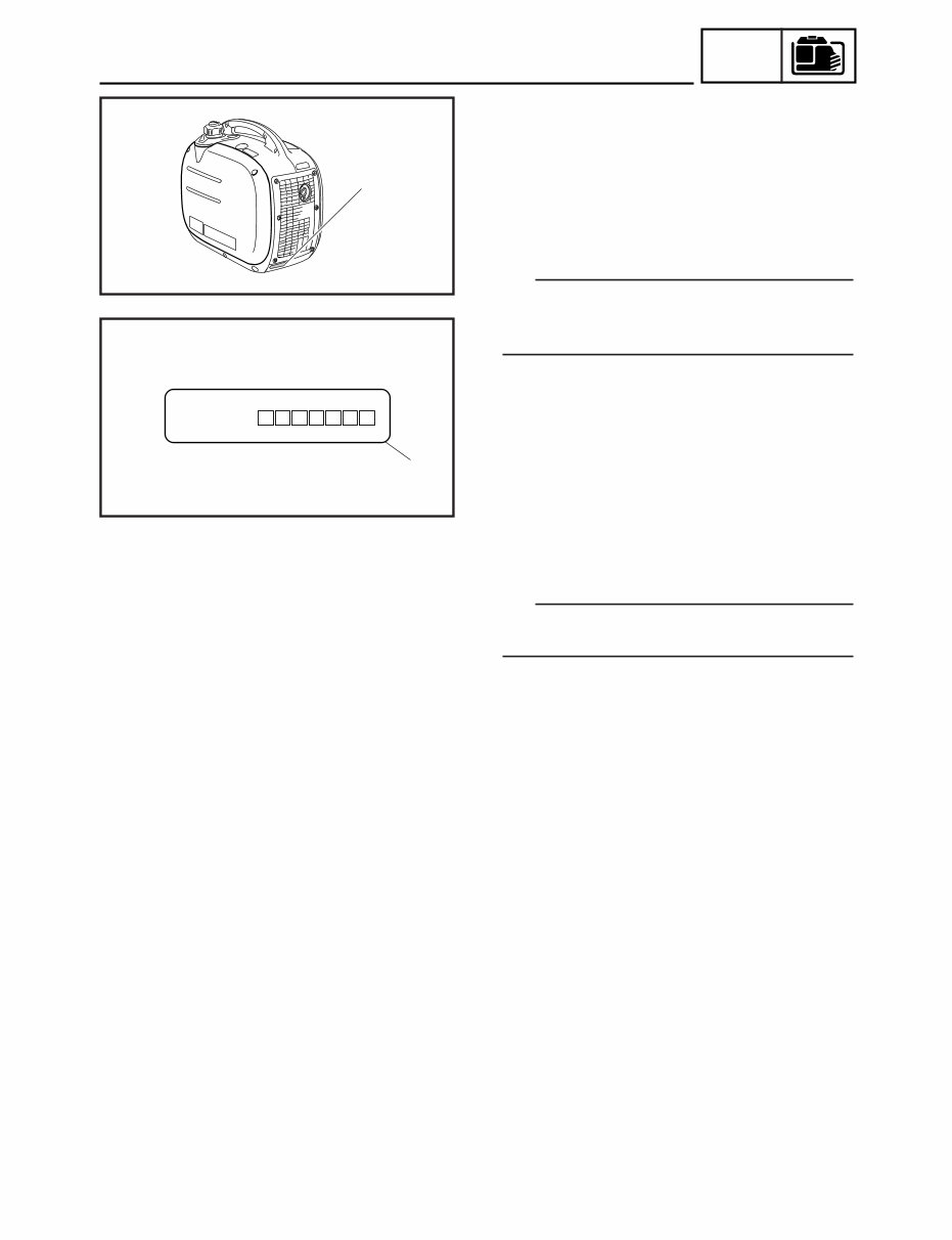
MACHINE IDENTIFICATION
1
Serial NO.
7DK
–
7DK-24163-00
2
GENERAL INFORMATION
MACHINE IDENTIFICATION
SERIAL NUMBER
The serial number is printed at the line 2 on a
label 1 which is affixed to the generator as
shown.
TIP
The first three characters of this number are
for model identification, the remaining digits
are the unit production number.
STARTING SERIAL NUMBER
7DK-090201-
TIP
Designs and specifications are subject to
change without notice.
GEN
INFO
1-2
SVU1030
SVU1040
SVU1050
SVU1060
SVU1070
SVU1080
SVU1090
SVU1100
IMPORTANT INFORMATION
PREPARATION FOR REMOVAL AND DISASSEMBLY
CAUTION ON SERVICE
1. Fire prevention
When servicing the engine, always keep the engine and yourself
away from fire.
NOTES ON SERVICE
1. Correct tools
Be sure to use the correct special tool for the job to guard
against damage.
IMPORTANT INFORMATION
2. Oil, grease and seals
Be sure to use genuine Yamaha oils, grease and sealers, or the
equivalents.
3. Expendable parts
Always replace the gaskets, O-rings, cotter pins and circlips with
new parts when servicing engine.
4. Tightening torque
Be sure to follow torque specifications. When tightening bolts,
nuts or screws, start with the largest-diameter fastener and work
from an inner position to an outer position in a crisscross pat-
tern.
5. Notes on disassembly and assembly
a. Parts should be cleaned in solvent and blown dry with com-
pressed air after disassembly.
b. Contact surfaces of moving parts should be oiled when
reassembled.
c. Make sure that the parts, move smoothly after each section of
the machine is assembled.
1
2
3
4
5
GEN
INFO
1-3
SVU1110
SVU1120
ALL REPLACEMENT PARTS
We recommend the use of genuine Yamaha parts for all replace-
ments. Use oil and/or grease, recommended by Yamaha, for
assembly and adjustment.
GASKETS, OIL SEALS, AND O-RINGS
1. All gaskets, seals, and O-rings should be replaced when an
engine is overhauled. All gaskets surfaces, oil seal lips, and O-
rings must be cleaned.
2. Properly oil all mating parts and bearings during reassembly.
Apply grease to the oil seal lips.
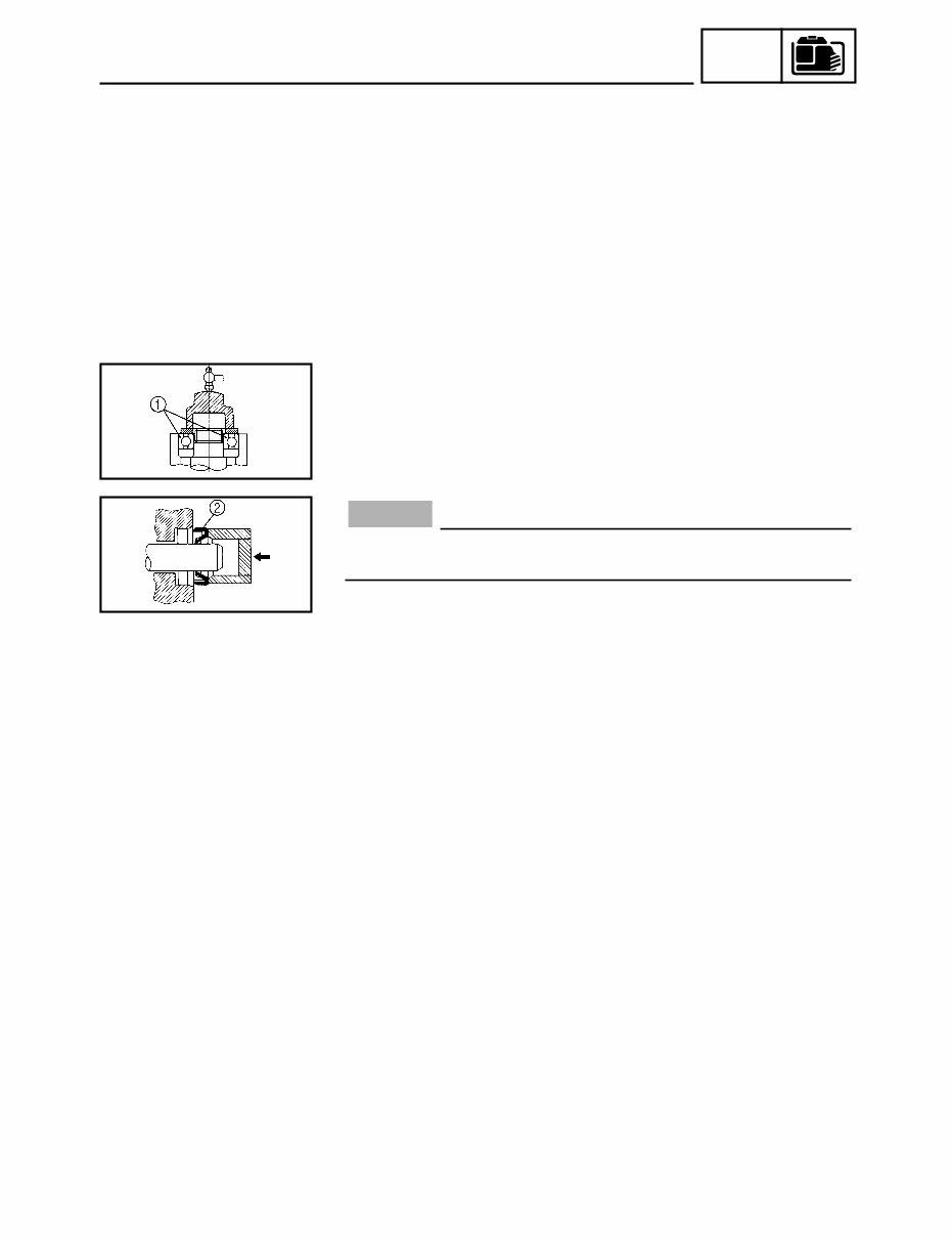
BEARINGS AND OIL SEALS
Install the bearing(s) 1 and oil seal(s) 2 with their manufacture’ s
marks or numbers facing outward. (In other words, the stamped let-
ters must be on the side exposed to view.) When installing oil
seal(s), apply a light coating of lightweight lithium base grease to
the seal lip(s). Oil the bearings liberally when installing.
Do not use compressed air to spin the bearings dry. This
causes damage to the bearing surfaces.
NOTICE
IMPORTANT INFORMATION
You're Reading a Preview
What's Included?
Fast Download Speeds
Online & Offline Access
Access PDF Contents & Bookmarks
Full Search Facility
Print one or all pages of your manual
$31.99
Viewed 44 Times Today


Secure transaction
What's Included?
Fast Download Speeds
Online & Offline Access
Access PDF Contents & Bookmarks
Full Search Facility
Print one or all pages of your manual
$31.99
Get the comprehensive service repair manual for the Yamaha Generator EF2000is. This manual contains complete and easy-to-follow service information essential for both professional mechanics and DIY enthusiasts.
Whether you're looking for detailed maintenance procedures or troubleshooting guidance, this manual has you covered. It's an invaluable resource for ensuring the optimal performance and longevity of your EF2000is generator.


