

Yamaha EF1000 Generator Full Service & Repair Manual
What's Included?
Fast Download Speeds
Online & Offline Access
Access PDF Contents & Bookmarks
Full Search Facility
Print one or all pages of your manual
EF1000
Service Manual
7FL-28197-11

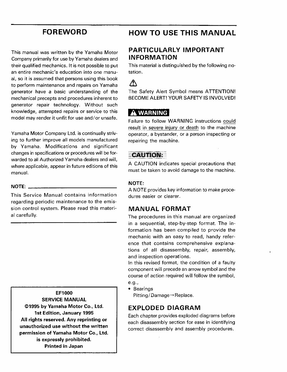
FOREWORD
This manual was written by the Yamaha Motor
Company primarily for use by Yamaha dealers and
their qualified mechanics. It is not possible to put
an entire mechanic's education into one manu-
al, so it is assumed that persons using this book
to perform maintenance and repairs on Yamaha
generator have a basic understanding of the
mechanical precepts and procedures inherent to
generator repair technology. Without such
knowledge, attempted repairs or service to this
model may render it unfit for use and/or unsafe.
Yamaha Motor Company Ltd. is continually striv-
ing to further improve all models manufactured
by Yamaha. Modifications and significant
changes in specifications or procedures will be for-
warded to all Authorized Yamaha dealers and will,
where applicable, appear in future editions of this
manual.
NOTE: --------------------------
This Service Manual contains information
regarding periodic maintenance to the emis-
sion control system. Please read this materi-
al carefully.
EF1000
SERVICE MANUAL
©1995 by Yamaha Motor Co., Ltd.
1st Edition, January 1995
All rights reserved. Any reprinting or
unauthorized use without the written
permission of Yamaha Motor Co., ltd.
is expressly prohibited.
Printed in Japan
HOW TO USE THIS MANUAL
PARTICULARLY IMPORTANT
INFORMATION
This material is distinguished by the following no-
tation.
&
The Safety Alert Symbol means ATTENTION!
BECOME ALERT! YOUR SAFETY IS INVOLVED!
A WARNING
Failure to follow WARNING instructions could
result in severe injury or death to the machine
operator, a bystander, or a person inspecting or
repairing the machine.
I"lllli•lz•·•••·••·•
A CAUTION indicates special precautions that
must be taken to avoid damage to the machine.
NOTE:
A NOTE provides key information to make proce-
dures easier or clearer.
MANUAL FORMAT
The procedures in this manual are organized
in a sequential, step-by-step format. The in-
formation has been compiled to provide the
mechanic with an easy to read, handy refer-
ence that contains comprehensive explana-
tions of all disassembly, repair, assembly,
and inspection operations.
In this revised format, the condition of a faulty
component will precede an arrow symbol and the
course of action required will follow the symbol,
e.g.,
• Bearings
Pitting/ Damage~ Replace.
EXPLODED DIAGRAM
Each chapter provides exploded diagrams before
each disassembly section for ease in identifying
correct disassembly and assembly procedures.
CD
GEN
....
,.
INFO
@
•llllull
ENG
1•1
@
I sPEc I g-1
®
~
@
l
@
~
©
[ij]
@
1
-
m
®
&
a
(2)
l~5~l§ll
@
IELEciUI
(j)
~
®
1~1
@
§
@
1
9
®
~
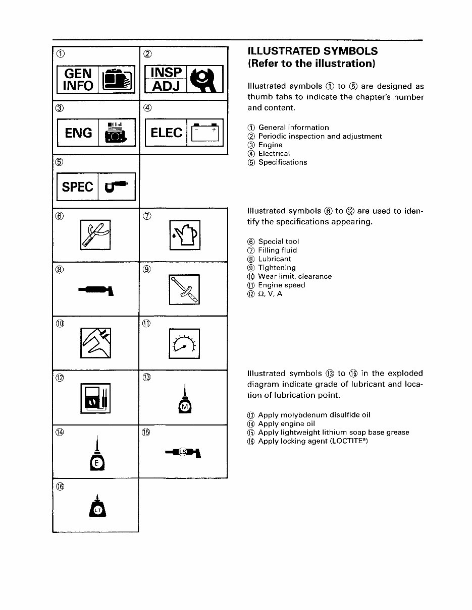
ILLUSTRATED SYMBOLS
(Refer to the illustration)
Illustrated symbols CD to @ are designed as
thumb tabs to indicate the chapter's number
and content.
<D General information
~ Periodic inspection and adjustment
®Engine
® Electrical
® Specifications
Illustrated symbols @to @ are used to iden-
tify the specifications appearing.
® Special tool
(]) Filling fluid
@ Lubricant
® Tightening
@ Wear limit, clearance
(j]) Engine speed
@Q,V,A
Illustrated symbols @ to @ in the exploded
diagram indicate grade of lubricant and loca-
tion of lubrication point.
@ Apply molybdenum disulfide oil
@ Apply engine oil
@ Apply lightweight lithium soap base grease
@ Apply locking agent (LOCTITE®)
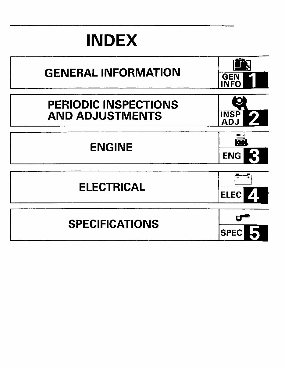
INDEX
GENERAL INFORMATION
PERIODIC INSPECTIONS
AND ADJUSTMENTS
ENGINE
ELECTRICAL
SPECIFICATIONS
111
GEN
INFO
•II II nil
-
ENG
ELEC
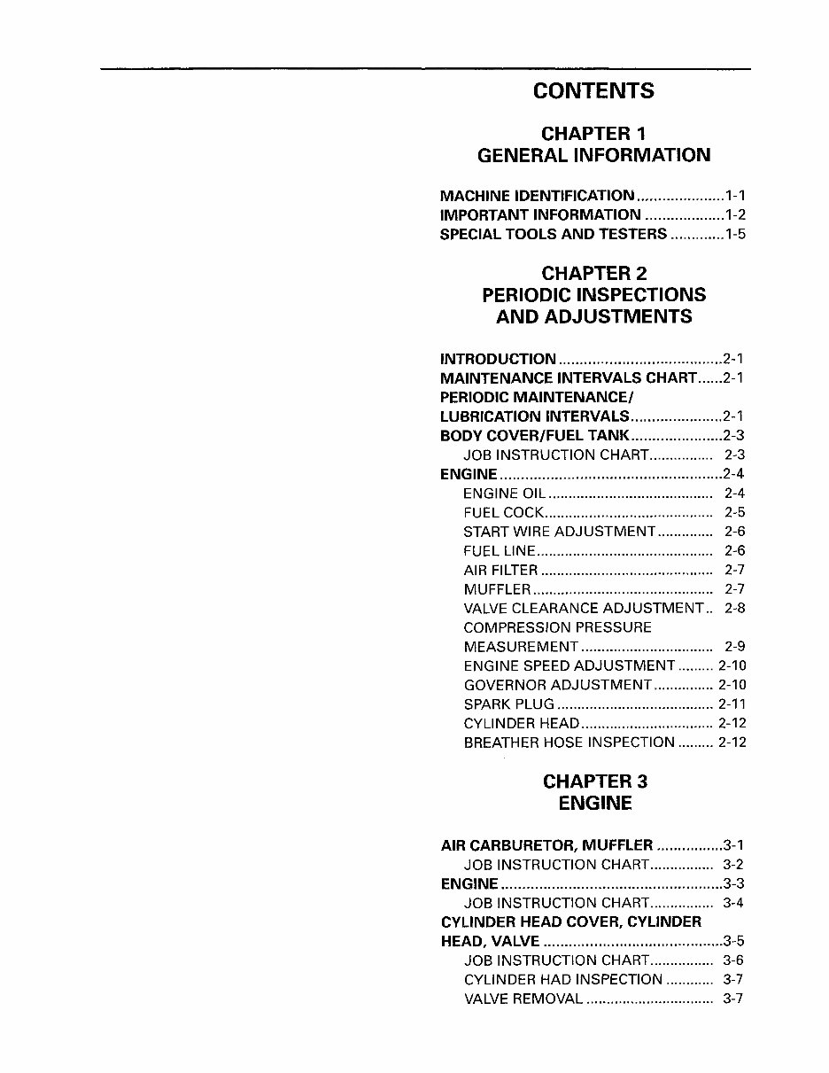
CONTENTS
CHAPTER 1
GENERAL INFORMATION
MACHINE IDENTIFICATION ..................... 1-1
IMPORTANT INFORMATION ................... 1-2
SPECIAL TOOLS AND TESTERS ............. 1-5
CHAPTER 2
PERIODIC INSPECTIONS
AND ADJUSTMENTS
INTRODUCTION ....................................... 2-1
MAINTENANCE INTERVALS CHART ...... 2-1
PERIODIC MAINTENANCE/
LUBRICATION INTERVALS ...................... 2-1
BODY COVER/FUEL TANK ...................... 2-3
JOB INSTRUCTION CHART................ 2-3
ENGINE ..................................................... 2-4
ENGINE OIL......................................... 2-4
FUEL COCK.......................................... 2-5
START WIRE ADJUSTMENT.............. 2-6
FUEL LINE............................................ 2-6
AIR FILTER........................................... 2-7
MUFFLER ............................................. 2-7
VALVE CLEARANCE ADJUSTMENT .. 2-8
COMPRESSION PRESSURE
MEASUREMENT................................. 2-9
ENGINE SPEED ADJUSTMENT ......... 2-10
GOVERNOR ADJUSTMENT ............... 2-10
SPARK PLUG ....................................... 2-11
CYLINDER HEAD ................................. 2-12
BREATHER HOSE INSPECTION ......... 2-12
CHAPTER3
ENGINE
AIR CARBURETOR, MUFFLER ................ 3-1
JOB INSTRUCTION CHART ................ 3-2
ENGINE .....................................................3-3
JOB INSTRUCTION CHART ................ 3-4
CYLINDER HEAD COVER, CYLINDER
HEAD, VALVE ........................................... 3-5
JOB INSTRUCTION CHART ................ 3-6
CYLINDER HAD INSPECTION ............ 3-7
VALVE REMOVAL ................................ 3-7
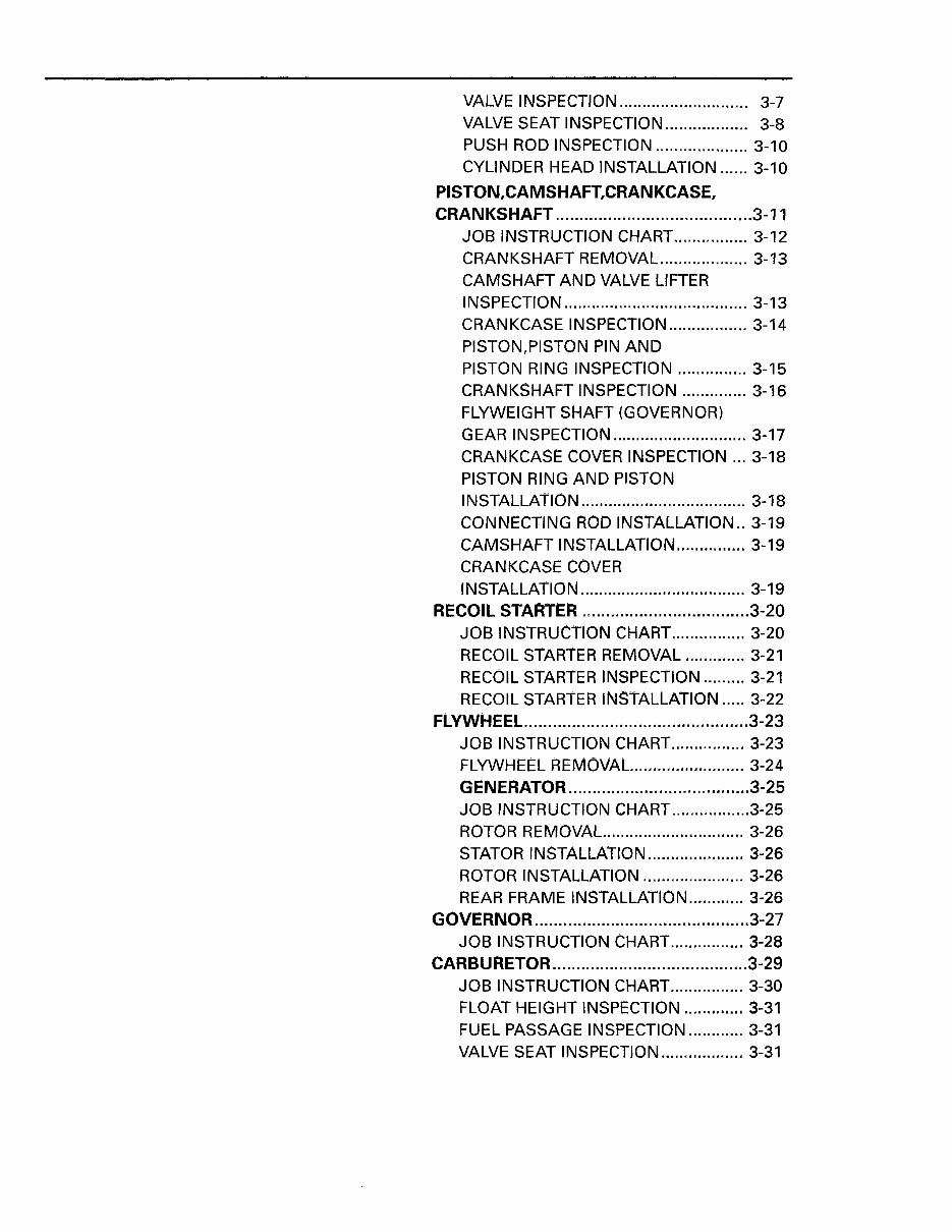
VALVE INSPECTION ............................ 3-7
VALVE SEAT INSPECTION .................. 3-8
PUSH ROD INSPECTION .................... 3-10
CYLINDER HEAD INSTALLATION ...... 3-10
PISTON,CAMSHAFT,CRANKCASE,
CRANKSHAFT ....................................... .. 3-11
JOB INSTRUCTION CHART ................ 3-12
CRANKSHAFT REMOVAL ................... 3-13
CAMSHAFT AND VALVE LIFTER
INSPECTION ........................................ 3-13
CRANKCASE INSPECTION ................. 3-14
PISTON,PISTON PIN AND
PISTON RING INSPECTION ............... 3-15
CRANKSHAFT INSPECTION .............. 3-16
FLYWEIGHT SHAFT (GOVERNOR)
GEAR INSPECTION ............................. 3-17
CRANKCASE COVER INSPECTION ... 3-18
PISTON RING AND PISTON
INSTALLATION .................................... 3-18
CONNECTING ROD INSTALLATION .. 3-19
CAMSHAFT INSTALLATION ............... 3-19
CRANKCASE COVER
INSTALLATION .................................... 3-19
RECOIL STARTER ................................... 3-20
JOB INSTRUCTION CHART ................ 3-20
RECOIL STARTER REMOVAL ............. 3-21
RECOIL STARTER INSPECTION ......... 3-21
RECOIL STARTER INSTALLATION ..... 3-22
FLYWHEEL ............................................... 3-23
JOB INSTRUCTION CHART ................ 3-23
FLYWHEEL REMOVAL. ........................ 3-24
GENERATOR ............................ .......... 3-25
JOB INSTRUCTION CHART ................. 3-25
ROTOR REMOVAL. .............................. 3-26
STATOR INSTALLATION ..................... 3-26
ROTOR INSTALLATION ...................... 3-26
REAR FRAME INSTALLATION ............ 3-26
GOVERNOR ............................................. 3-27
JOB INSTRUCTION CHART ................ 3-28
CARBURETOR ........................................ . 3-29
JOB INSTRUCTION CHART ................ 3-30
FLOAT HEIGHT INSPECTION ............. 3-31
FUEL PASSAGE INSPECTION ............ 3-31
VALVE SEAT INSPECTION .................. 3-31
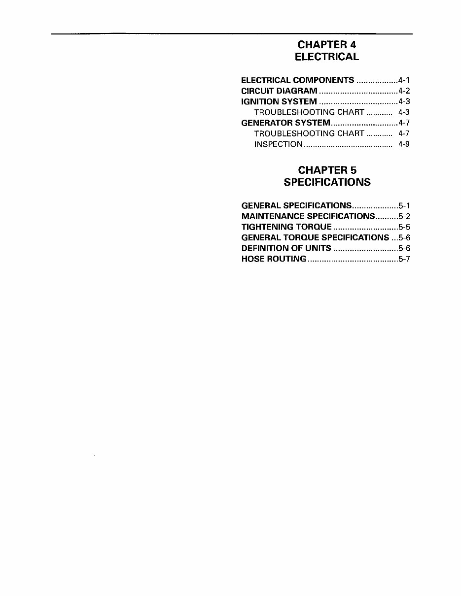
CHAPTER 4
ELECTRICAL
ELECTRICAL COMPONENTS ................. .4-1
CIRCUIT DIAGRAM .................................. 4-2
IGNITION SYSTEM .................................. 4-3
TROUBLESHOOTING CHART ............ 4-3
GENERATOR SVSTEM ............................. 4-7
TROUBLESHOOTING CHART ............ 4-7
INSPECTION ........................................ 4-9
CHAPTER 5
SPECIFICATIONS
GENERAL SPECIFICATIONS .................... 5-1
MAINTENANCE SPECIFICATIONS .......... 5-2
TIGHTENING TORQUE ............................ 5-5
GENERAL TORQUE SPECIFICATIONS ... 5-6
DEFINITION OF UNITS ............................ 5-6
HOSE ROUTING ....................................... 5-7
MACHINE IDENTIFICATION
~~~~.
790-027
1-1
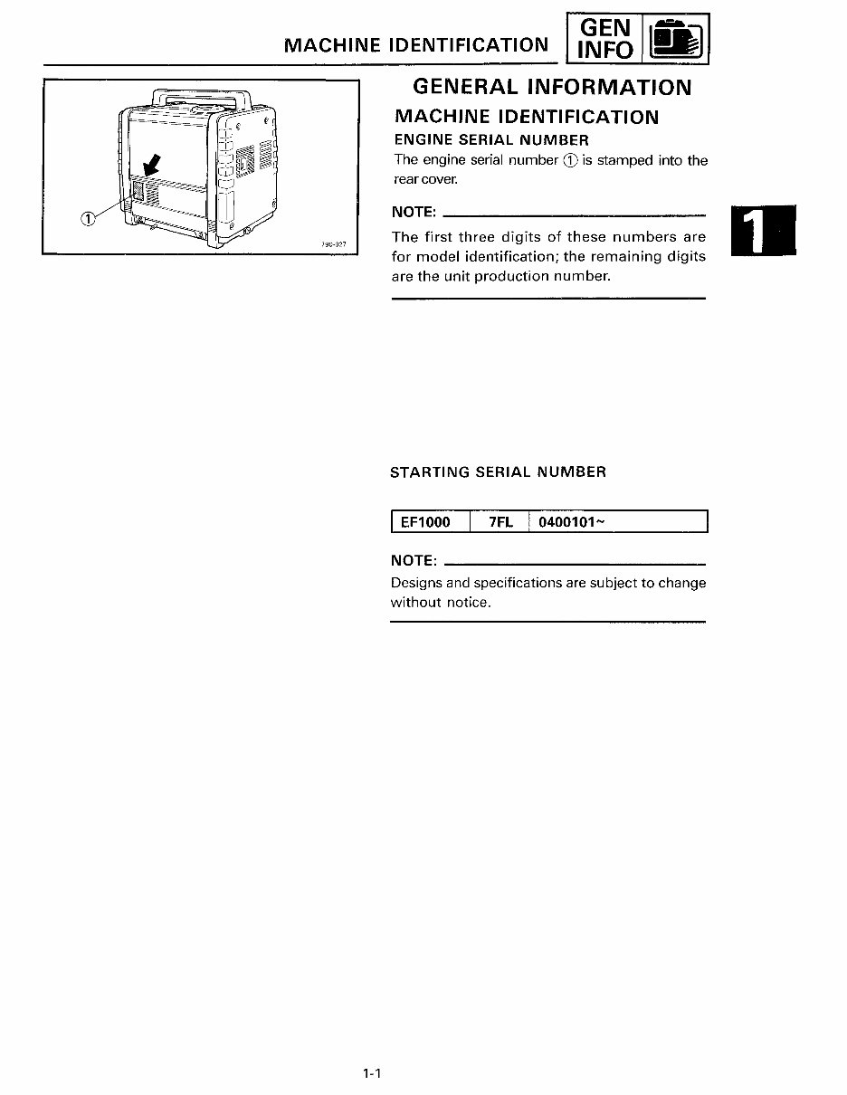
GENERAL INFORMATION
MACHINE IDENTIFICATION
ENGINE SERIAL NUMBER
The engine serial number CD is stamped into the
rear cover.
NOTE: ________________________ ___
The first three digits of these numbers are
for model identification; the remaining digits
are the unit production number.
STARTING SERIAL NUMBER
I EF1000 7FL I 0400101-
NOTE: --------------------------
Designs and specifications are subject to change
without notice.
IMPORTANT INFORMATION
[ __ ]
1-2
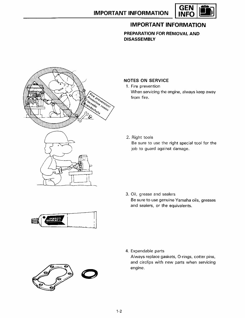
IMPORTANT INFORMATION
PREPARATION FOR REMOVAL AND
DISASSEMBLY
NOTES ON SERVICE
1. Fire prevention
When servicing the engine, always keep away
from fire.
2. Right tools
Be sure to use the right special tool for the
job to guard against damage.
3. Oil, grease and sealers
Be sure to use genuine Yamaha oils, greases
and sealers, or the equivalents.
4. Expendable parts
Always replace gaskets, 0-rings, cotter pins,
and circlips with new parts when servicing
engine.
You're Reading a Preview
What's Included?
Fast Download Speeds
Online & Offline Access
Access PDF Contents & Bookmarks
Full Search Facility
Print one or all pages of your manual
$39.99
Viewed 55 Times Today


Secure transaction
What's Included?
Fast Download Speeds
Online & Offline Access
Access PDF Contents & Bookmarks
Full Search Facility
Print one or all pages of your manual
$39.99
- This is a complete factory service repair workshop manual for the Yamaha EF1000 Generator.
- It covers all repairs, servicing, and troubleshooting procedures with detailed photos & diagrams.
- Professional mechanics and technicians use this manual, which includes step-by-step instructions and highly detailed exploded diagrams & pictures.
- You can print out a single page or the entire manual as per your choice.
- This manual can be used on multiple computers without any limitations or trial periods.
- There is no expiry date, renewal fee, or limitations; it can be used for life.
- It is fully compatible with all Windows & MAC computers.
Thanks for looking at this item, please click on the button to get the manual.


