

TECHNICAL MANUAL
WESTERBEKE
4.5 KW BCG ··60 Hz
7.0 KW BCG ·60 Hz
7.0 KW BCGA· 60 Hz
3.5 KW BCG • 50 Hz
5.0 KW BCG • 50 Hz
MARINE GASOLINE
GENERATOR SETS
Publication #038747
Edition One
March 1990
l·v#'WESTERBEKE
.
~ WESTERBEKE CORPORATION· MYLES STANDISH INDUSTRIAL PARK
150 JOHN HANCOCK ROAD, TAUNTON, MA 02780-7319 U.S.A.
. TEL; (508)823-7877. FAX: (508)B84-9688 • WEBSITE: www.WESTERBEKE.COM

Gasoline with an ETHANOL content
higher than 10% (E10) is not allowed
and may void warranty.
Engines & Generators
SAFETY PRECAUTIONS
The following symbols appear in this manual to call attention
to and emphasize conditions potentially dangerous to the
operator.
IWARNINGI
The above symbol is used in the manual to warn of possible
serious personal injury or loss of life.
CAUTION
The above symbol is used in the manual to caution personnel
of possible damage to equipment.
Read the manual carefully and thoroughly before attempting
to operate the equipment. Know when dangerous conditions
can exist and take necessary precautions to protect personnel
and equipment.
Fuels, exhaust gases, batteries, electrical equipment, and
moving and hot parts are potential hazards that could result in
serious personal injury or death. Follow recommended proce-
dures carefully.
I>Jways operate bilge blowers for at least five minutes before
starting a gasoline-fueled engine; ensure no gasoline fumes are
present before starting.
• Prevent Electric Shock
Shut off electric power before accessing electrical equip-
ment.
Use insulated mats whenever working on electrical equip-
ment.
Make sure your clothing is dry, not damp (particularly
shoes), and keep your skin surfaces dry when handling
electrical equipment.
Remove wristwatch and jewelry when working on electri-
cal equipment.
Do not connect utility shore power to vessel's AC circuits,
except through a ship-to-shore double-throw transfer
switch. Damage to vessel's AC generator may result if this
is not done.
Be extremely careful when working on electrical com-
ponents. High voltage can cause injury or death.
• Exhaust Gases Are Toxic
Ensure that the exhaust system is adequate to expel gases
discharged from the engine. Check exhaust system
regularly for leaks and make sure the exhaust manifolds
are securely attached and no warping exists.
Be sure the unit and its surroundings are well-ventilated.
• Use Extreme Care When Handling Engine Fuel
(A constant danger of explosion or fire exists)
Do not fill fuel tank(s) while the engine is running.
Do not smoke or use an open flame near the engine or the
fuel tank.
• Do Not Alter or Modify the Fuel System
Be sure all fuel supplies have a positive shut-off valve.
Be certain fuel line fittings are adequately tightened and
free of leaks.
Make sure a fire extinguisher is installed nearby and is
properly maintained. Be familiar with its proper use. Ex-
tinguishers rated ABC by the NFPA are appropriate for all
applications encountered in this environment.
• Use Extreme Care When Servicing Batteries
Wear rubber gloves, a rubber apron, and eye protection
when servicing batteries.
Lead acid batteries emit hydrogen, a highly-explosive gas,
which can be ignited by electrical arcing or by a lighted
cigarette, cigar, or pipe. Do not smoke or allow an open
flame near the battery being serviced. Shut off all electrical
equipment in the vicinity to prevent electrical arCing
during servicing.
• Avoid Moving parts
Do not service the unit while the unit is running; if a
situation arises in which it is absolutely necessary to make
operating adjustments, use extreme care to avoid moving
parts and hot exhaust system components.
Do not wear loose clothing or jewelry when servicing
equipment; avoid wearing loose jackets, shirts or sleeves,
rings, necklaces, or bracelets that might be caught in
moving parts.
Make sure all attaching hardware is properly tightened.
Keep protective shields and guards in their respective
place at all times.
Do not check fluid levels or the drive-belt's tension while
the unit is operating.
Do not work on the equipment when mentally or physically
incapacitated by fatigue.

IMPORTANT
PRODUCT SOFTWARE DISCLAIMER
Product software of all kinds, such as brochures, drawings, technical data, operator's and workshop manuals,
parts lists and parts price lists, and other information, instructions and specifications provided from sources
other than Westerbeke, is not within Westerbeke's control and; accordingly, is provided to Westerbeke
customers only as a courtesy and service. Westerbeke cannot be responsible for the content of such
software, makes no warranties or representations with respect thereto, including the accuracy,
timeliness or completeness thereof, and will in no event be liable for any type of damages or injury
incurred in connection with, or arising out of, the furnishing or use of such software.
For example, components and subassemblies incorporated in Westerbeke's products and supplied by others
(such as engine blocks, fuel systems and components, transmissions, electrical components, pumps and
other products) are generally supported by their manufacturers with their own software, and Westerbeke
must depend on such software for the design of Westerbeke's own product software. Such software may
be outdated and no longer accurate. Routine changes made by Westerbeke's suppliers, ofwhich Westerbeke
rarely has notice in advance, are frequently not reflected in the supplier's software until after such changes
take place.
Westerbeke customers should also keep in mind the time span between printings of Westerbeke product
software and the unavoidable existence of earlier, non-current, Westerbeke software editions in the field.
Additionally, most Westerbeke products include customer-requested special features that frequently do not
include complete documentation.
In summation, product software provided with Westerbeke products, whether from Westerbeke or other
suppliers, must not and cannot be relied upon exclusively as the definitive authority on the respective product.
It not only makes good sense but is imperative that appropriate representatives of Westerbeke or the supplier
in question be consulted to determine the accuracy and currency of the product software being consulted
by the customer.
1 Westerbeke Generators
TABLE OF CONTENTS
Section ......................................................................... Page
4.5 KW BCG GENERAL SPECIFICATIONS .......................9
4.5 KW BCG SYSTEM SPECIFICATIONS ........................ 10
7.0 KW BCG & BCGA
GENERAL SPECiFiCATIONS ........................................... 13
7.0 KW BCG & BCGA
SYSTEM SPECIFICATIONS ............................................. 14
4.5 KWBCG
ENGINE SERVICE SPECIFICATIONS ............................. 17
7.0 KW BCG & BCGA
ENGINE SERVICE SPECIFICATIONS ............................. 27
ENGINE DESCRIPTION ................................................... 37
GENERATOR OVERHAUL.. ............................................ ..46
PREPARATIONS FOR OVERHAUL.. ................................ 47
DISASSEMBLY FOR OVERHAUL .................................... 48
ENGINE DISASSEMBL Y................................................... 50
REMOVING THE CYLINDER HEAD
FROM THE CYLINDER BLOCK ........................................ 53
CYLINDER HEAD DISASSEMBLY ................................... 54
CYLINDER BLOCK DISASSEMBLY ................................. 57
SPECIAL SERVICE TOOLS .............................................. 61
CYLINDER HEAD AND ENGINE BLOCK
INSPECTION AND REPAIR .............................................. 63
ENGINE INSPECTION AND REPAIR ............................... 64
SUBASSEMBLY INSPECTION,
REPAIR AND ASSEMBLY ................................................. 81
ENGINE ASSEMBL Y....................................................... 101
CYLINDER BLOCK ASSEMBLY ..................................... 1 02
Westerbeke Generators 2
TABLE OF CONTENTS
(CONTINUED)
CYUNDER HEAD ASSEMBLY ....................................... 109
LUBRICATION SYSTEM ................................................ 119
GENERATOR DESCRIPTION
AND MODEL RATING .................................................... 130
TROUBLESHOOTING AND ADJUSTMENTS
FOR THE BC GENERATOR ........................................... 131
COMPONENT RESISTANCE VALUES .......................... 134
GENERATOR TROUBLESHOOTING ............................ 143
GENERATOR HERTZ (CYCLE)
AND VOLTAGE CHANGES ............................................ 145
FIELD FABRICATED TOOLS ......................................... 147
INDEX ............................................................................. 151
3 Westerbeke Generators
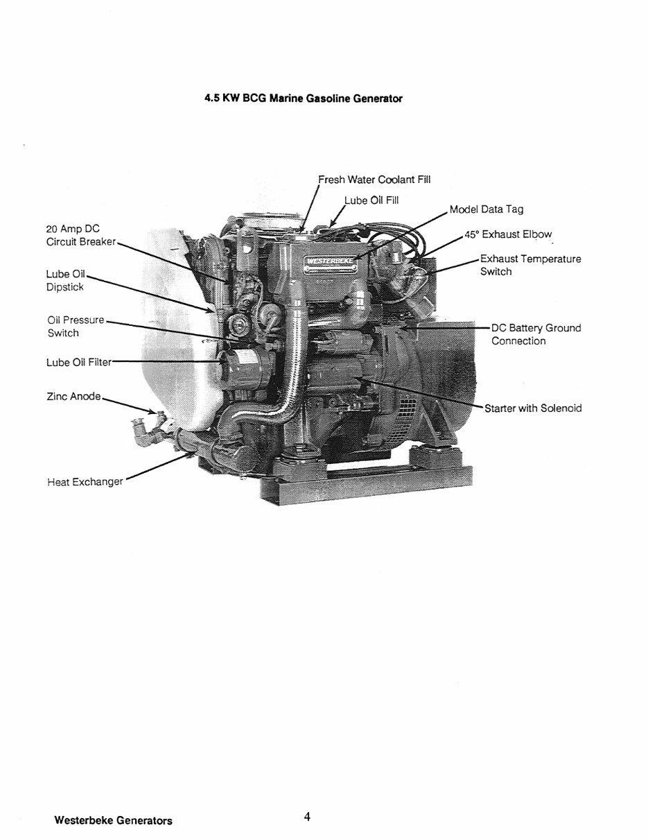
20 Amp DC
Circuit Breaker
Lube Oil
Dipstick
4.5 KW BeG Marine Gasoline Generator
Fresh Water Coolant Fill
Oil Pressure ,,----..;~...i;.;._
Switch
lube Oii >::ill'oy·--
Zinc Anode
Heat Exchanger
Westerbeke Generators
4
Exhaust Temperature
Switch
DC Battery Ground
Connection
Starter with Solenoid
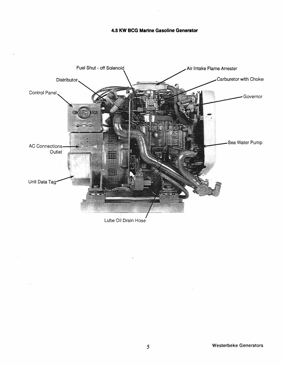
4.5 KW BeG Marine Gasoline Generator
Fuel Shut - off Snl.:llnnlf1
Air Intake Flame Arrester
Governor
AC
Unit Data T
lube Oil Drain Hose
5
Westerbeke Generators
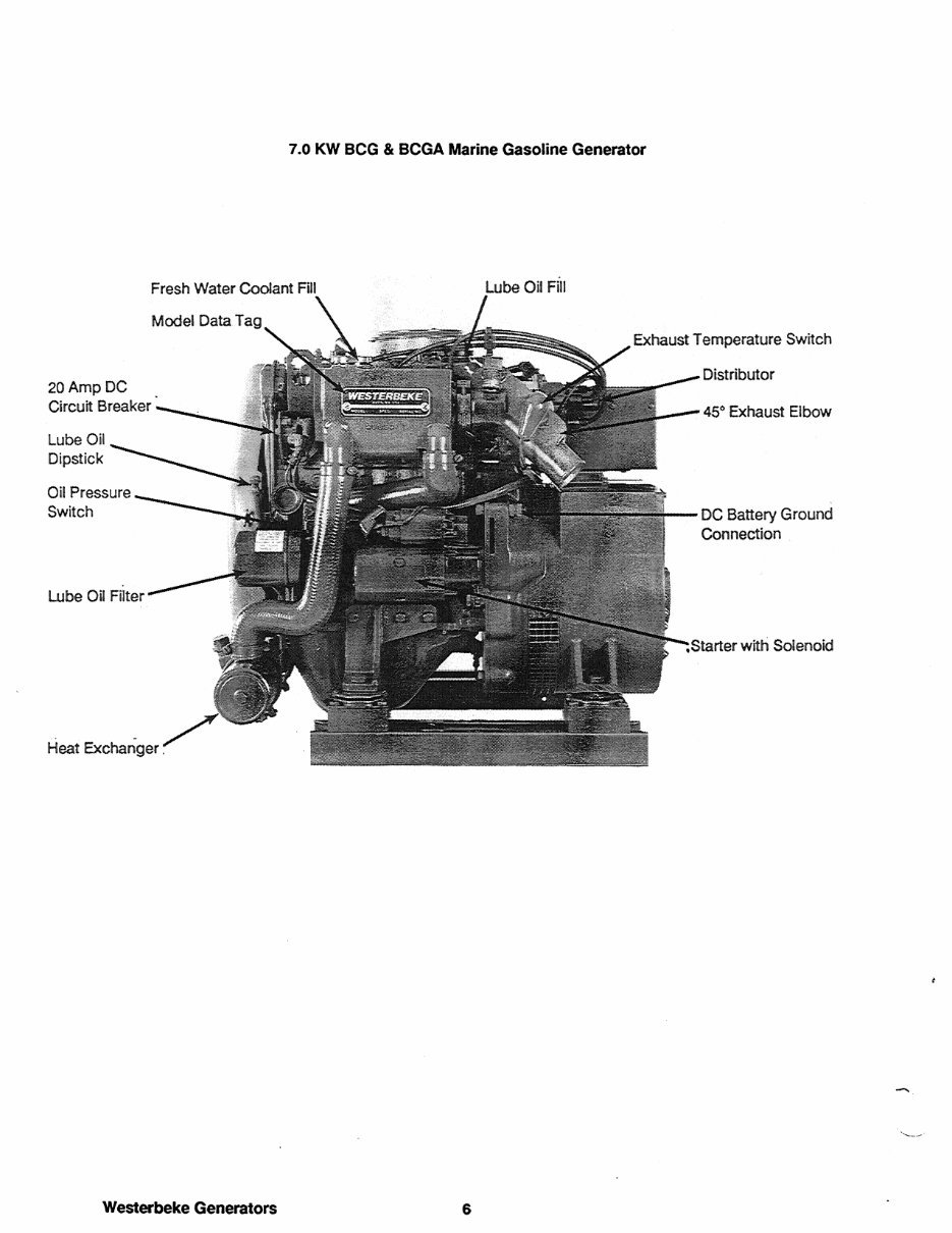
20 Amp DC
Circuit Breaker
Lube Oil
Dipstick
Oil Pressure
Switch
Heat Exchanger.
Westerbeke Generators
7.0 KW BCG & BCGA Marine Gasoline Generator
Exhaust Temperature Switch
6
DC Battery Ground
Connection .
-Rt~rt_ with Solenoid
You're Reading a Preview
What's Included?
Fast Download Speeds
Online & Offline Access
Access PDF Contents & Bookmarks
Full Search Facility
Print one or all pages of your manual
$35.99
Westerbeke Carbureted Gasoline Generators 3.5 KW BCG-50 Hz Marine Gasoline*Factory Service / Repair/ Workshop Manual Instant Dow
Viewed 79 Times Today

What's Included?
Fast Download Speeds
Online & Offline Access
Access PDF Contents & Bookmarks
Full Search Facility
Print one or all pages of your manual
$35.99

Secure transaction
What's Included?
Fast Download Speeds
Online & Offline Access
Access PDF Contents & Bookmarks
Full Search Facility
Print one or all pages of your manual
Description
This manual provides maintenance and repair procedures for the Westerbeke Carbureted Gasoline Generators 3.5 KW BCG-50 Hz Marine Gasoline. It offers step-by-step instructions, detailed exploded pictures, and diagrams to facilitate correct and efficient completion of all repair procedures. The manual covers the following models:
- 3.5 KW BCG-50 Hz Marine Gasoline Generator Sets
The service repair manual includes the following sections:
- 4.5 KW BCG General Specifications (Page 9)
- 4.5 KW BCG System Specifications (Page 10)
- 7.0 KW BCG & BCGA General Specifications (Page 13)
- 7.0 KW BCG & BCGA System Specifications (Page 14)
- 4.5 KW BCG Engine Service Specifications (Page 17)
- 7.0 KW BCG & BCGA Engine Service Specifications (Page 27)
- Engine Description (Page 37)
- Generator Overhaul (Page 46)
- Preparations for Overhaul (Page 47)
- Disassembly for Overhaul (Page 48)
- Engine Disassembly (Page 50)
- Removing the Cylinder Head from the Cylinder Block (Page 53)
- Cylinder Head Disassembly (Page 54)
- Cylinder Block Disassembly (Page 57)
- Special Service Tools (Page 61)
- Cylinder Head and Engine Block Inspection and Repair (Page 63)
- Engine Inspection and Repair (Page 64)
- Subassembly Inspection, Repair, and Assembly (Page 81)
- Engine Assembly (Page 101)
- Cylinder Block Assembly (Page 102)
- Cylinder Head Assembly (Page 109)
- Lubrication System (Page 119)
- Generator Description and Model Rating (Page 130)
- Troubleshooting and Adjustments for the BC Generator (Page 131)
- Component Resistance Values (Page 134)
- Generator Troubleshooting (Page 143)
- Generator Hertz (Cycle) and Voltage Changes (Page 145)
- Field Fabricated Tools (Page 147)
- Index (Page 151)
Instant delivery eliminates shipping costs and waiting time. The manual is accessible immediately upon secure payment completion and is printable on all major operating systems. It is compatible with Adobe Reader and Win.


