

KOHLER Generator Service Workshop Manual
What's Included?
Fast Download Speeds
Online & Offline Access
Access PDF Contents & Bookmarks
Full Search Facility
Print one or all pages of your manual
Residential/Commercial Generator Sets
Models:
14RES/RESL
20RES/RESL
Controllers:
RDC Residential Digital Control
DC Digital Control
TP-6735 9/10
Service


Table of Contents
TP-6735 9/10 Table of Contents
Safety Precautions and Instructions 7 ........................................................
Introduction 11 ...............................................................................
List of Related Materials 11 .....................................................
Service Assistance 12 ........................................................................
Section 1 Specifications 13 ...................................................................
1.1 Introduction 13 ..........................................................
1.2 Controller Specifications 13 ...............................................
1.3 Engine Service 13 .......................................................
1.4 Engine Specifications 13 ..................................................
1.5 Alternator Specifications 14 ...............................................
1.6 Torque Specifications 14 ..................................................
1.7 Service View 15 .........................................................
Section 2 Scheduled Maintenance 17 ..........................................................
2.1 Service Schedule 17 .....................................................
2.2 Lubrication System 19 ....................................................
2.2.1 Low Oil Pressure Shutdown 19 ....................................
2.2.2 Oil Check 19 ....................................................
2.2.3 Engine Oil Recommendation 19 ....................................
2.2.4 Oil Change Procedure 19 .........................................
2.2.5 Oil Cooler, 14RES/RESL 20 .......................................
2.2.6 Oil Cooler, 20RES/RESL 21 .......................................
2.3 Spark Plugs 21 ..........................................................
2.4 Air Cleaner Service 22 ....................................................
2.4.1 Air Cleaner, 14RES/RESL Models 22 ...............................
2.4.2 Air Cleaner, 20RES/RESL Models 23 ...............................
2.5 Cooling System 23 .......................................................
2.6 Stepper Motor Coupling 24 ................................................
2.7 Exhaust System 24 ......................................................
2.8 Battery 24 ...............................................................
2.9 Battery Charger 25 .......................................................
2.10 Storage Procedure 26 ....................................................
2.10.1 Lubricating System 26 ............................................
2.10.2 Fuel System 26 ..................................................
2.10.3 Cylinder Lubrication 26 ...........................................
2.10.4 Exterior Preparation 26 ...........................................
2.10.5 Battery 26 .......................................................
Section 3 Troubleshooting 27 .................................................................
3.1 Introduction 27 ..........................................................
3.2 Initial Checks 27 .........................................................
3.3 Controller Service Access 27 ..............................................
3.4 Troubleshooting Chart 27 .................................................
3.5 Controller Troubleshooting 36 .............................................
Section 4 Controller 37 .......................................................................
4.1 Introduction 37 ..........................................................
4.2 RDC and DC Generator Set/ Transfer Switch Controllers 37 ...................
4.3 Controller Power 37 ......................................................
4.4 Controls and Indicators 38 ................................................
4.4.1 LED Display 39 ..................................................
4.4.2 Controller Keypad 39 .............................................
4.4.3 LED Indicators 40 ................................................

Table of Contents, continued
TP-6735 9/10 Table of Contents
4.5 Generator Set Operation 41 ...............................................
4.5.1 Engine Start Crank Cycle 41 .......................................
4.5.2 Local Starting and Stopping 41 ....................................
4.5.3 Automatic Operation with Model RRT Transfer Switch 41 ..............
4.5.4 Automatic Operation with Model RDT or RSB Transfer Switches 41 .....
4.6 Exercise 42 .............................................................
4.6.1 Unloaded Exercise with Diagnostic Test 42 ..........................
4.6.2 Low-Speed Diagnostics 42 ........................................
4.6.3 Loaded Exercise 42 ..............................................
4.6.4 Exerciser Reset and Disable 43 ....................................
4.6.5 Power Failure During Exercise Cycle 43 .............................
4.7 Test 43 .................................................................
4.7.1 Unloaded Test 43 ................................................
4.7.2 Loaded Test 44 ..................................................
4.7.3 Power Failure During Test Cycle 44 .................................
4.8 Faults 45 ...............................................................
4.8.1 Warnings 45 .....................................................
4.8.2 Shutdowns 45 ...................................................
4.8.3 ATS Communication Errors 45 .....................................
4.8.4 Resetting the Controller after a Fault Shutdown 45 ....................
4.9 Event History 48 .........................................................
4.10 Model RRT Transfer Switch Operation 49 ...................................
4.10.1 Source Availability 49 .............................................
4.10.2 ATS Control Sequence of Operation 49 .............................
4.10.3 Time Delays 49 ..................................................
4.10.4 Engine and Transfer Time Delays 50 ...............................
4.10.5 Load Control Time Delay 50 .......................................
4.10.6 Model RRT ATS Connection 50 ....................................
4.11 Controller Configuration and Adjustment 51 .................................
4.11.1 SiteTech Software 51 .............................................
4.11.2 Controller Configuration 51 ........................................
4.11.3 Controller Time Out 51 ............................................
4.11.4 Controller Firmware Version Number 51 .............................
4.11.5 Voltage and Frequency Adjustments 52 .............................
4.12 Calibration 52 ...........................................................
4.12.1 Calibrate Function 52 .............................................
4.12.2 Calibration Factor 52 .............................................
4.13 Controller Circuit Board 54 ................................................
4.13.1 Relays and LEDs 54 ..............................................
4.13.2 Controller Fuse F2 54 ............................................
4.14 Controller Replacement 55 ................................................
Section 5 Component Testing and Adjustment 57 ..............................................
5.1 Theory of Operation 57 ...................................................
5.2 Separate Excitation 57 ....................................................
5.3 Stator 59 ................................................................
5.4 Main Field (Rotor) 61 .....................................................
5.4.1 Rotor Continuity and Resistance Tests 61 ...........................
5.5 Slip Rings 62 ............................................................
5.6 Brushes 62 ..............................................................
5.7 Voltage Connections 63 ...................................................
5.7.1 Voltage Connections, Single-Phase Models 63 .......................
5.7.2 Voltage Regulation 63 ............................................

Table of Contents, continued
TP-6735 9/10 Table of Contents
5.8 Voltage Adjustment 63 ....................................................
5.8.1 Voltage Adjustment Procedure 64 ..................................
5.8.2 Volts per Hertz (Hz) Adjustments (Droop) 64 .........................
5.9 Governor System 66 .....................................................
5.9.1 Operation 66 ....................................................
5.9.2 Initial Checks 66 .................................................
5.9.3 Hunting/Surging 66 ...............................................
5.9.4 Governor System/Magnetic Pickup Operation Test 67 .................
5.9.5 Frequency Adjustment 70 .........................................
5.10 Fault Shutdown Tests 71 ..................................................
5.10.1 Controller Fault Shutdown Functions 71 .............................
5.10.2 Fault Shutdown Switches 72 .......................................
5.11 Fuel Systems 74 .........................................................
5.11.1 Fuel Solenoid Valve 74 ...........................................
5.11.2 Digital Spark Advance Ignition (DSAI) Timing 75 .....................
5.11.3 Fuel Regulators 75 ...............................................
5.11.4 Fuel Conversion, 20RES/RESL 76 .................................
5.11.5 Fuel Conversion, 14RES/RESL 77 .................................
5.11.6 Fuel Metering Valve Adjustment, 14RES/RESL Only 78 ...............
5.12 Starter Relay 80 .........................................................
5.13 Continuity Checks 81 .....................................................
5.14 Circuit Protection 82 ......................................................
5.14.1 Line Circuit Breaker 82 ...........................................
5.14.2 Fuses and Mini-Breaker 82 ........................................
Section 6 Disassembly/Reassembly 83 ........................................................
6.1 Initial Steps 83 ...........................................................
6.2 Disassembly 84 ..........................................................
6.3 Reassembly 90 ..........................................................
Section 7 Wiring Diagrams 95 ................................................................
Appendix A Abbreviations 99 ..................................................................
Appendix B Common Hardware Application Guidelines 101 ........................................
Appendix C General Torque Specifications 102 ...................................................
Appendix D Common Hardware Identification 103 .................................................
Appendix E Common Hardware List 104 .........................................................
Appendix F Controller Parameters (SiteTech) 107 .................................................

TP-6735 9/10 6
TP-6735 9/10 7 Safety Precautions and Instructions
Safety Precautions and Instructions
IMPORTANT SAFETY INSTRUCTIONS.
Electromechanical equipment,
including generator sets, transfer
switches, switchgear, and accessories,
can cause bodily harm and pose
life-threatening danger when
improperly installed, operated, or
maintained. To prevent accidents be
aware of potential dangers and act
safely. Read and follow all safety
precautions and instructions. SAVE
THESE INSTRUCTIONS.
This manual has several types of safety
precautions and instructions: Danger,
Warning, Caution, and Notice.
DANGER
Danger indicates the presence of a
hazard that will cause severe
personal injury, death, or
substantial property damage.
WARNING
Warning indicates the presence of a
hazard that can cause severe
personal injury, death, or
substantial property damage.
CAUTION
Caution indicates the presence of a
hazard that will or can cause minor
personal injury or property damage.
NOTICE
Notice communicates installation,
operation, or maintenance information
that is safety related but not hazard
related.
Safety decals affixed to the equipment
in prominent places alert the operator
or service technician to potential
hazards and explain how to act safely.
The decals are shown throughout this
publication to improve operator
recognition. Replace missing or
damaged decals.
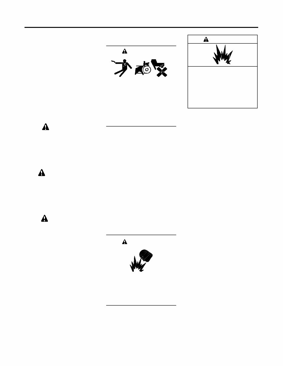
Accidental Starting
Accidental starting.
Can cause severe injury or death.
Disconnect the battery cables before
working on the generator set.
Remove the negative (--) lead first
when disconnecting the battery.
Reconnect the negative (--) lead last
when reconnecting the battery.
WARNING
Disabling the generator set.
Accidental starting can cause
severe injury or death. Before
working on the generator set or
connected equipment, disable the
generator set as follows: (1) Move the
generator set master switch to the OFF
position. (2) Disconnect the power to
the battery charger. (3) Remove the
battery cables, negative (--) lead first.
Reconnect the negative (--) lead last
when reconnecting the battery. Follow
these precautions to prevent starting of
the generator set by an automatic
transfer switch, remote start/stop
switch, or engine start command from a
remote computer.
Battery
Sulfuric acid in batteries.
Can cause severe injury or death.
Wear protective goggles and
clothing. Battery acid may cause
blindness and burn skin.
WARNING
Explosion.
Can cause severe injury or death.
Relays in the battery charger
cause arcs or sparks.
Locate the battery in a well-ventilated
area. Isolate the battery charger from
explosive fumes.
WARNING
Battery electrolyte is a diluted
sulfuric acid. Battery acid can cause
severe injury or death. Battery acid
can cause blindness and burn skin.
Always wear splashproof safety
goggles, rubber gloves, and boots
when servicing the battery. Do not
open a sealed battery or mutilate the
battery case. If battery acid splashes in
the eyes or on the skin, immediately
flush the affected area for 15 minutes
with large quantities of clean water.
Seek immediate medical aid in the case
of eye contact. Never add acid to a
battery after placing the battery in
service, as this may result in hazardous
spattering of battery acid.
Battery acid cleanup. Battery acid
can cause severe injury or death.
Battery acid is electrically conductive
and corrosive. Add 500 g (1 lb.) of
bicarbonate of soda (baking soda) to a
container with 4 L (1 gal.) of water and
mix the neutralizing solution. Pour the
neutralizing solution on the spilled
battery acid and continue to add the
neutralizing solution to the spilled
battery acid until all evidence of a
chemical reaction (foaming) has
ceased. Flush the resulting liquid with
water and dry the area.
Battery gases. Explosion can cause
severe injury or death. Battery gases
can cause an explosion. Do not smoke
or permit flames or sparks to occur near
a battery at any time, particularly when
it is charging. Do not dispose of a
battery in a fire. To prevent burns and
sparks that could cause an explosion,
avoid touching the battery terminals
with tools or other metal objects.
TP-6735 9/10 8 Safety Precautions and Instructions
Remove all jewelry before servicing the
equipment. Discharge static electricity
from your body before touching
batteries by first touching a grounded
metal surface away from the battery. To
avoid sparks, do not disturb the battery
charger connections while the battery
is charging. Always turn the battery
charger off before disconnecting the
battery connections. Ventilate the
compartments containing batteries to
prevent accumulation of explosive
gases.
Battery short circuits. Explosion
can cause severe injury or death.
Short circuits can cause bodily injury
and/or equipment damage.
Disconnect the battery before
generator set installation or
maintenance. Remove all jewelry
before servicing the equipment. Use
tools with insulated handles. Remove
the negative (--) lead first when
disconnecting the battery. Reconnect
the negative (--) lead last when
reconnecting the battery. Never
connect the negative (--) battery cable
to the positive (+) connection terminal
of the starter solenoid. Do not test the
battery condition by shorting the
terminals together.
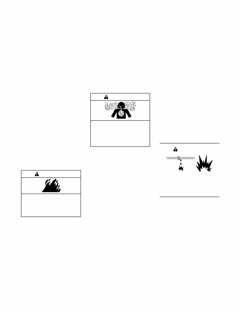
Engine Backfire/Flash
Fire
Fire.
Can cause severe injury or death.
Do not smoke or permit flames or
sparks near fuels or the fuel system.
WARNING
Servicing the fuel system. A flash
fire can cause severe injury or death.
Do not smoke or permit flames or
sparks near the carburetor, fuel line,
fuel filter, fuel pump, or other potential
sources of spilled fuels or fuel vapors.
Catch fuels in an approved container
when removing the fuel line or
carburetor.
Servicing the air cleaner. A sudden
backfire can cause severe injury or
death. Do not operate the generator
set with the air cleaner removed.
Combustible materials. A fire can
cause severe injury or death.
Generator set engine fuels and fuel
vapors are flammable and explosive.
Handle these materials carefully to
minimize the risk of fire or explosion.
Equip the compartment or nearby area
with a fully charged fire extinguisher.
Select a fire extinguisher rated ABC or
BC for electrical fires or as
recommended by the local fire code or
an authorized agency. Train all
personnel on fire extinguisher
operation and fire prevention
procedures.
Exhaust System
Carbon monoxide.
Can cause severe nausea,
fainting, or death.
The exhaust system must be
leakproof and routinely inspected.
WARNING
Generator set operation. Carbon
monoxide can cause severe nausea,
fainting, or death. Carbon monoxide
is an odorless, colorless, tasteless,
nonirritating gas that can cause death if
inhaled for even a short time. Avoid
breathing exhaust fumes when working
on or near the generator set. Never
operate the generator set inside a
building unless the exhaust gas is
piped safely outside. Never operate
the generator set where exhaust gas
could accumulate and seep back inside
a potentially occupied building.
Carbon monoxide detectors.
Carbon monoxide can cause severe
nausea, fainting, or death. Install
carbon monoxide detectors on each
level of any building adjacent to the
generator set. Locate the detectors to
adequately warn the building’s
occupants of the presence of carbon
monoxide. Keep the detectors
operational at all times. Periodically
test and replace the carbon monoxide
detectors according to the
manufacturer’s instructions.
Carbon monoxide symptoms.
Carbon monoxide can cause severe
nausea, fainting, or death. Carbon
monoxide is a poisonous gas present in
exhaust gases. Carbon monoxide is an
odorless, colorless, tasteless,
nonirritating gas that can cause death if
inhaled for even a short time. Carbon
monoxide poisoning symptoms include
but are not limited to the following:
D Light-headedness, dizziness
D Physical fatigue, weakness in
joints and muscles
D Sleepiness, mental fatigue,
inability to concentrate
or speak clearly, blurred vision
D Stomachache, vomiting, nausea
If experiencing any of these symptoms
and carbon monoxide poisoning is
possible, seek fresh air immediately
and remain active. Do not sit, lie down,
or fall asleep. Alert others to the
possibility of carbon monoxide
poisoning. Seek medical attention if
the condition of affected persons does
not improve within minutes of breathing
fresh air.
Fuel System
Explosive fuel vapors.
Can cause severe injury or death.
Use extreme care when handling,
storing, and using fuels.
WARNING
TP-6735 9/10 9 Safety Precautions and Instructions
The fuel system. Explosive fuel
vapors can cause severe injury or
death. Vaporized fuels are highly
explosive. Use extreme care when
handling and storing fuels. Store fuels
in a well-ventilated area away from
spark-producing equipment and out of
the reach of children. Never add fuel to
the tank while the engine is running
because spilled fuel may ignite on
contact with hot parts or from sparks.
Do not smoke or permit flames or
sparks to occur near sources of spilled
fuel or fuel vapors. Keep the fuel lines
and connections tight and in good
condition. Do not replace flexible fuel
lines with rigid lines. Use flexible
sections to avoid fuel line breakage
caused by vibration. Do not operate the
generator set in the presence of fuel
leaks, fuel accumulation, or sparks.
Repair fuel systems before resuming
generator set operation.
Gas fuel leaks. Explosive fuel
vapors can cause severe injury or
death. Fuel leakage can cause an
explosion. Check the LP vapor gas or
natural gas fuel system for leakage by
using a soap and water solution with
the fuel system test pressurized to
6--8 ounces per square inch
(10--14 inches water column). Do not
use a soap solution containing either
ammonia or chlorine because both
prevent bubble formation. A successful
test depends on the ability of the
solution to bubble.
LP liquid withdrawal fuel leaks.
Explosive fuel vapors can cause
severe injury or death. Fuel leakage
can cause an explosion. Check the LP
liquid withdrawal gas fuel system for
leakage by using a soap and water
solution with the fuel system test
pressurized to at least 90 psi
(621 kPa). Do not use a soap solution
containing either ammonia or chlorine
because both prevent bubble
formation. A successful test depends
on the ability of the solution to bubble.
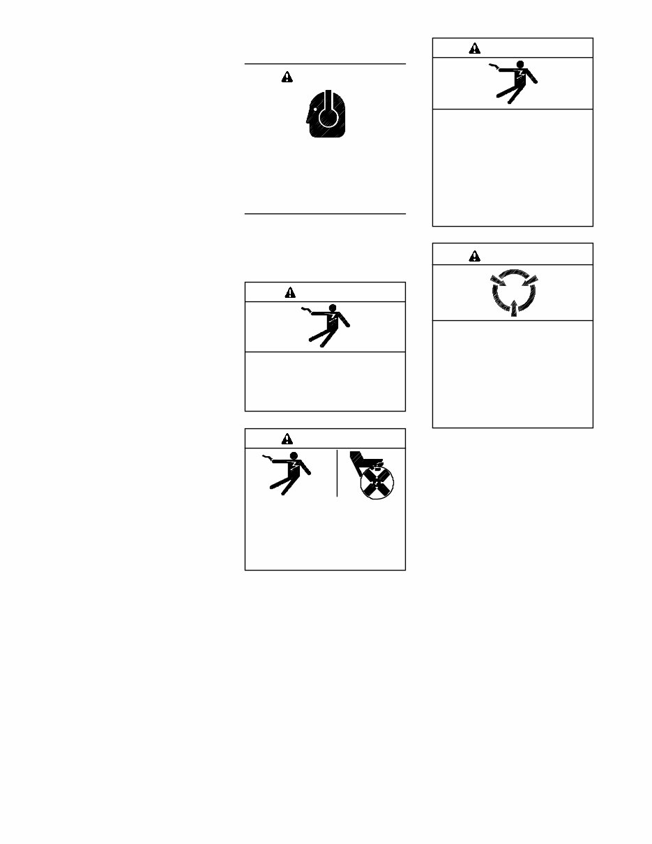
Hazardous Noise
Hazardous noise.
Can cause hearing loss.
Never operate the generator set
without a muffler or with a faulty
exhaust system.
CAUTION
Hazardous Voltage/
Moving Parts
Hazardous voltage.
Will cause severe injury or death.
Disconnect all power sources before
opening the enclosure.
DANGER
Hazardous voltage.
Can cause severe injury or death.
Operate the generator set only when
all guards and electrical enclosures
are in place.
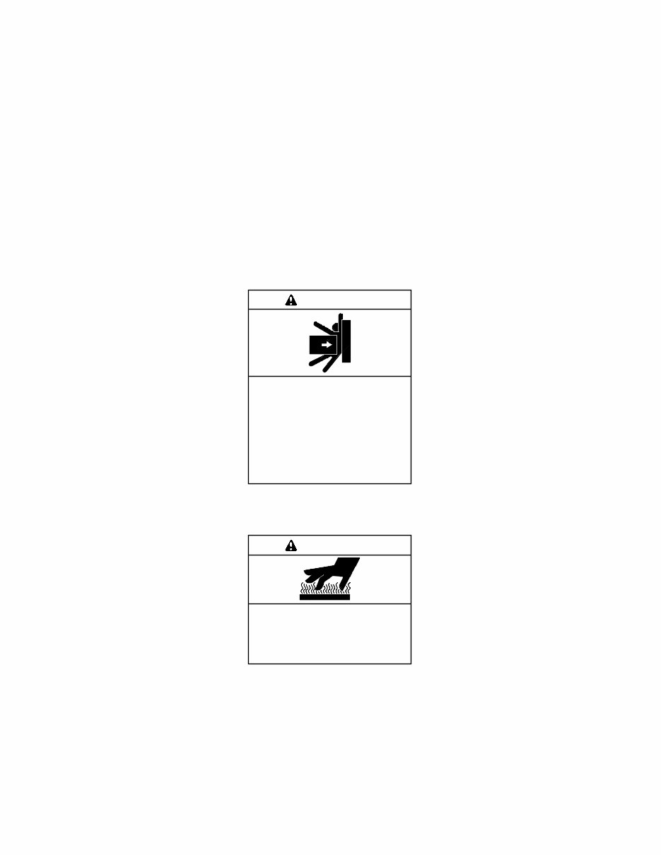
Moving parts.
WARNING
Hazardous voltage.
Backfeed to the utility system can
cause property damage, severe
injury, or death.
If the generator set is used for
standby power, install an automatic
transfer switch to prevent inadvertent
interconnection of standby and
normal sources of supply.
WARNING
Welding the generator set.
Can cause severe electrical
equipment damage.
Never weld components of the
generator set without first
disconnecting the battery, controller
wiring harness, and engine electronic
control module (ECM).
CAUTION
Grounding electrical equipment.
Hazardous voltage can cause
severe injury or death. Electrocution
is possible whenever electricity is
present. Ensure you comply with all
applicable codes and standards.
Electrically ground the generator set,
transfer switch, and related equipment
and electrical circuits. Turn off the main
circuit breakers of all power sources
before servicing the equipment. Never
contact electrical leads or appliances
when standing in water or on wet
ground because these conditions
increase the risk of electrocution.
TP-6735 9/10 10 Safety Precautions and Instructions
Welding on the generator set. Can
cause severe electrical equipment
damage. Before welding on the
generator set perform the following
steps: (1) Remove the battery cables,
negative (--) lead first. (2) Disconnect
all engine electronic control module
(ECM) connectors. (3) Disconnect all
generator set controller and voltage
regulator circuit board connectors.
(4) Disconnect the engine battery-
charging alternator connections.
(5) Attach the weld ground connection
close to the weld location.
High voltage test. Hazardous
voltage can cause severe injury or
death. Follow the instructions of the
test equipment manufacturer when
performing high-voltage tests on the
rotor or stator. An improper test
procedure can damage equipment or
lead to generator set failure.
Connecting the battery and the
battery charger. Hazardous voltage
can cause severe injury or death.
Reconnect the battery correctly,
positive to positive and negative to
negative, to avoid electrical shock and
damage to the battery charger and
battery(ies). Have a qualified
electrician install the battery(ies).
Short circuits. Hazardous
voltage/current can cause severe
injury or death. Short circuits can
cause bodily injury and/or equipment
damage. Do not contact electrical
connections with tools or jewelry while
making adjustments or repairs.
Remove all jewelry before servicing the
equipment.
Electrical backfeed to the utility.
Hazardous backfeed voltage can
cause severe injury or death. Install
a transfer switch in standby power
installations to prevent the connection
of standby and other sources of power.
Electrical backfeed into a utility
electrical system can cause severe
injury or death to utility personnel
working on power lines.
Testing live electrical circuits.
Hazardous voltage or current can
cause severe injury or death. Have
trained and qualified personnel take
diagnostic measurements of live
circuits. Use adequately rated test
equipment with electrically insulated
probes and follow the instructions of the
test equipment manufacturer when
performing voltage tests. Observe the
following precautions when performing
voltage tests: (1) Remove all jewelry.
(2) Stand on a dry, approved electrically
insulated mat. (3) Do not touch the
enclosure or components inside the
enclosure. (4) Be prepared for the
system to operate automatically.
(600 volts and under)
Heavy Equipment
Unbalanced weight.
Improper lifting can cause severe
injury or death and equipment
damage.
Do not use lifting eyes.
Lift the generator set using lifting bars
inserted through the lifting holes on
the skid.
WARNING
Hot Parts
Hot engine and exhaust system.
Can cause severe injury or death.
Do not work on the generator set until
it cools.
WARNING
Servicing the alternator. Hot parts
can cause severe injury or death.
Avoid touching the alternator field or
exciter armature. When shorted, the
alternator field and exciter armature
become hot enough to cause severe
burns.
Servicing the exhaust system. Hot
parts can cause severe injury or
death. Do not touch hot engine parts.
The engine and exhaust system
components become extremely hot
during operation.
Servicing the engine heater. Hot
parts can cause minor personal
injury or property damage. Install the
heater before connecting it to power.
Operating the heater before installation
can cause burns and component
damage. Disconnect power to the
heater and allow it to cool before
servicing the heater or nearby parts.
Notice
NOTICE
Canadian installations only . For
standby service connect the output of
the generator set to a suitably rated
transfer switch in accordance with
Canadian Electrical Code, Part 1.
NOTICE
Electrostatic discharge damage.
Electrostatic discharge (ESD)
damages electronic circuit boards.
Prevent electrostatic discharge
damage by wearing an approved
grounding wrist strap when handling
electronic circuit boards or integrated
circuits. An approved grounding wrist
strap provides a high resistance (about
1 megohm), not a direct short, to
ground.
You're Reading a Preview
What's Included?
Fast Download Speeds
Online & Offline Access
Access PDF Contents & Bookmarks
Full Search Facility
Print one or all pages of your manual
$36.99
Viewed 76 Times Today


Secure transaction
What's Included?
Fast Download Speeds
Online & Offline Access
Access PDF Contents & Bookmarks
Full Search Facility
Print one or all pages of your manual
$36.99
Our digital manuals in PDF format cover a range of residential and commercial generator sets, including models such as 14RES/RESL and 20RES/RESL. These manuals are valuable resources for professional mechanics and DIY enthusiasts alike. They provide detailed information on various aspects of the generator sets, including controllers like RDC Residential Control and DC Control.


