Marine Generator Sets Models: 8C 8E 10C 10E 12.5C 12.5E TP-5413 5/01c Service Parts
Table of Contents Introduction 1 ................................................................. Numbering System Significance 1 ............................................... Illustrations 1 .................................................................. How to Find Part Numbers 1 .................................................... Hardware References 1 ........................................................ Specification Number Index 2 ................................................... Group 1: Gaskets and Seals 4 .................................................. Group 2: Cylinder Block 5 ...................................................... Group 3: Cylinder Head and Valves 6 ............................................ Group 4: Front Cover Assembly 7 ............................................... Group 5: Camshaft and Valve Control 8 .......................................... Group 5: Camshaft and Valve Control 9 .......................................... Group 6: Crankshaft and Piston 10 .............................................. Group 6: Crankshaft and Piston 11 .............................................. Group 7: Flywheel and Clutch 12 ................................................ Group 8: Oil Pump and Pan 13 .................................................. Group 9: Fan and Water Pump 14 ............................................... Group 10: Intake Manifold 15 ................................................... Group 12: Ignition Module and Spark Plugs 15 .................................... Group 101: Air Intake 16 ....................................................... Group 103: Fuel System 17 .................................................... Group 104: Cooling System 18 .................................................. Group 105: Engine 22 ......................................................... Group 107: Nameplate and Decals 26 ........................................... Group 108: Oil Pressure Switches 28 ............................................ Group 109: Skid and Plant Mounting 29 .......................................... Group 110: Water Temperature Switches 30 ...................................... Group 112: Starter 31 .......................................................... Group 201: Generator and Mounting 32 .......................................... Group 301: Controller and Mounting 34 .......................................... Group 01: Literature 36 ........................................................ Accessories 37 ................................................................ Appendix A Abbreviations A-1 .................................................. Appendix B Common Hardware Application Guidelines A-3 ......................... Appendix C General Torque Specifications A-4 .................................... Appendix D Common Hardware Identification A-5 ................................. Appendix E Common Hardware List A-6 .........................................
1 TP-5413 5/01 Introduction This manual lists service replacement parts for 8--12.5 kW generator sets. At the time of print this manual applied to the generator set specification (spec) numbers listed in the Specification Number Index. On occasion this manual may apply to specs not listed in the Specification Number Index. Information in this publication represents data available at the time of print. Kohler Co. reserves the right to change this publication and the products represented without notice and without any obligation or liability whatsoever. This manual includes the following main sections: Table of Contents. Lists the sections of the manual. Introduction (and other information sections). Contains introductory material about part numbers, illustrations, and hardware. Specification Number Index. Lists the generator set specs and groups. Group Parts Lists. List the part numbers of parts in the groups. Kit Sections. List modules and accessories and their parts. Appendices. Include Abbreviations, Common Hardware Application Guidelines, General Torque Specifications, Common Hardware Identification, and Common Hardware List. x:in:004:002 Numbering System Significance This manual uses the following numbering systems: Specification Number. The product identification number located on the generator set nameplate. Spec numbers break down into groups. Group Number. A unique number representing a parts group needed to assemble a generator set function. For example, Group 101 is the Air Intake group. Variation or Module Number. A group might have several variations. Each variation performs the same function with different parts lists. For example, a 50 Hz generator alternator and a 60 Hz generator alternator both perform the same function, however, with different parts. Each difference requires a group variation or module number. Part Number. The part number identifies an individual assembly, subassembly, component, or accessory kit. x:in:004:003:a Illustrations Illustrations (or exploded-view drawings) best representing the widest range of variations accompany most groups in this manual. Illustrations do not depict all details and may not show all parts. Do not use illustrations for assembly or disassembly instructions. x:in:004:004 How to Find Part Numbers Use the following steps to locate a service replacement part. 1. Locate the generator set nameplate to identify the generator set spec number . 2. Locate a second generator set nameplate listing accessories to identify installed modules. On some models the accessory nameplate is mounted inside the generator junction box. 3. Turn to the Specification Number Index. The first column lists the generator set spec numbers. The headings identify the groups of parts that make up the generator set. 4. Identify the group most likely to include the service part number. 5. Find the group variation number at the intersection of the spec number row and the group column. Note the variation number. 6. Page forward to locate the group identified in step 4 or find the appropriate page in the Table of Contents. 7. Find the part on the illustration and note the item number of the part or find the part description in the parts list. 8. Select the part number that corresponds to your group variation. The first column lists the illustration item number. Find the variation identified in the Specification Number Index or the module number found on the generator set nameplate in the appropriate column on the right side of the parts list table. Find the quantity used at the intersection of the item number row and the variation column. A blank space at the intersection means the variation/module does not use that part number. x:in:004:005 Hardware References Many common hardware items do not appear in parts manuals or will appear as common hardware entries. A common hardware entry lists the size of the hardware. For example, an item that appears as “Hardware, 3/8-16” in the text means that the piece is 3/8-16 size. Obtain common hardware locally or, if contacting the factory, use the Common Hardware List in the appendix to identify the common hardware part number and specifications. See Common Hardware Application Guidelines in the appendix for mating hardware instructions. Some hardware items require a specific size or some other characteristic. In that case, use the part number listed in the text. When replacing hardware, do not substitute inferior grade hardware. Replacement hardware grade should be equal to or better than the grade of the manufacturer’s original hardware. Use the Common Hardware List in the appendix to identify the common hardware hardness. x:in:004:006
This comprehensive manual is designed for DIY repair enthusiasts who work on generator service replacement parts for Kohler 8/10/12.5C and 8/10/12.5E Ford VSG411/413 Marine Generator Sets. It provides detailed information that can assist in identifying and locating the correct parts essential for repair and maintenance.
Table of Contents: Outlines the sections of the manual.
Introduction and Information Sections: Provides background material including part numbers, illustrations, and hardware details.
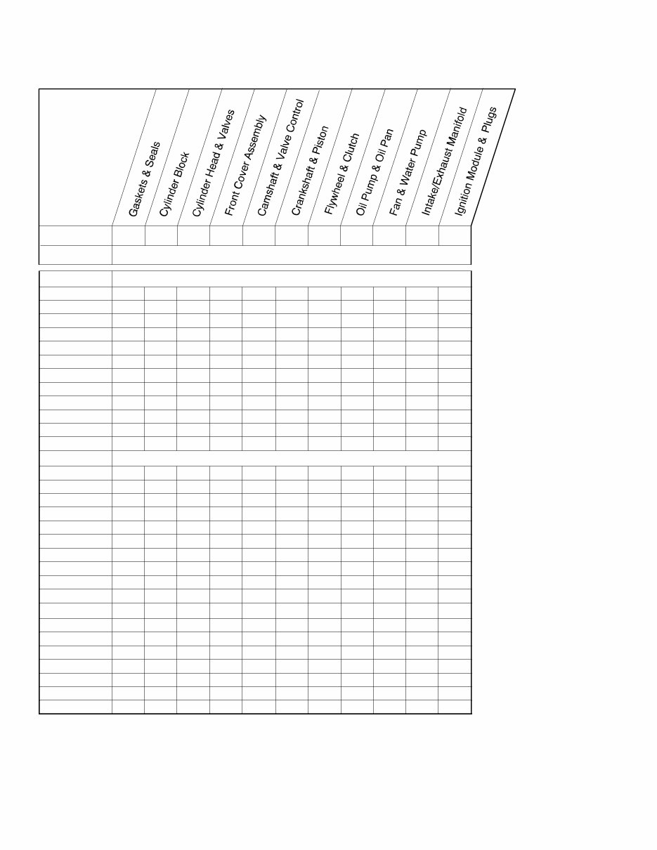
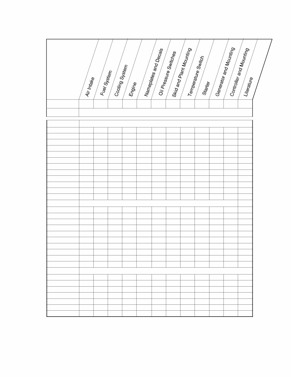
Specification Number Index: Presents generator set specifications and groups along with group parts lists.
Kit Sections: Details modules, accessories, and associated parts.
Appendices: Covers abbreviations, common hardware application guidelines, general torque specifications, common hardware identification, and a common hardware list.
Models Covered:
Kohler 8C
Kohler 8E
Kohler 10C
Kohler 10E
Kohler 12.5C
Kohler 12.5E
Manual Contents Include:
Introduction
Numbering System Significance
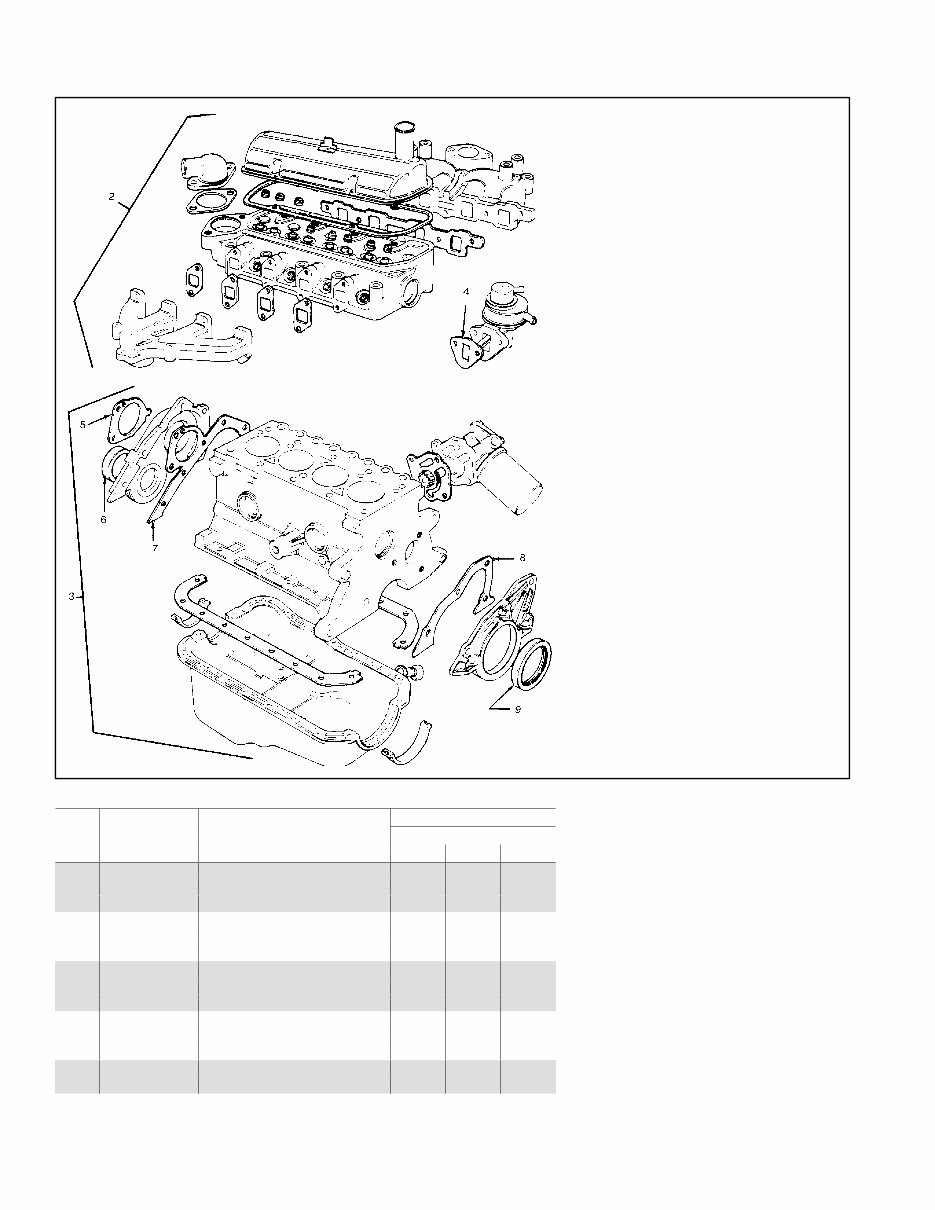
Illustrations
How to Find Part Numbers
Hardware References
Specification Number Index, including:
Gaskets and Seals
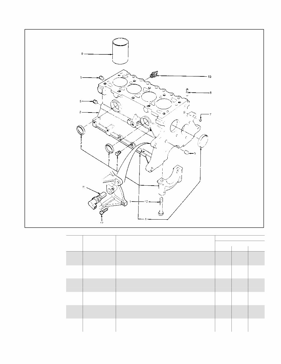
Cylinder Block
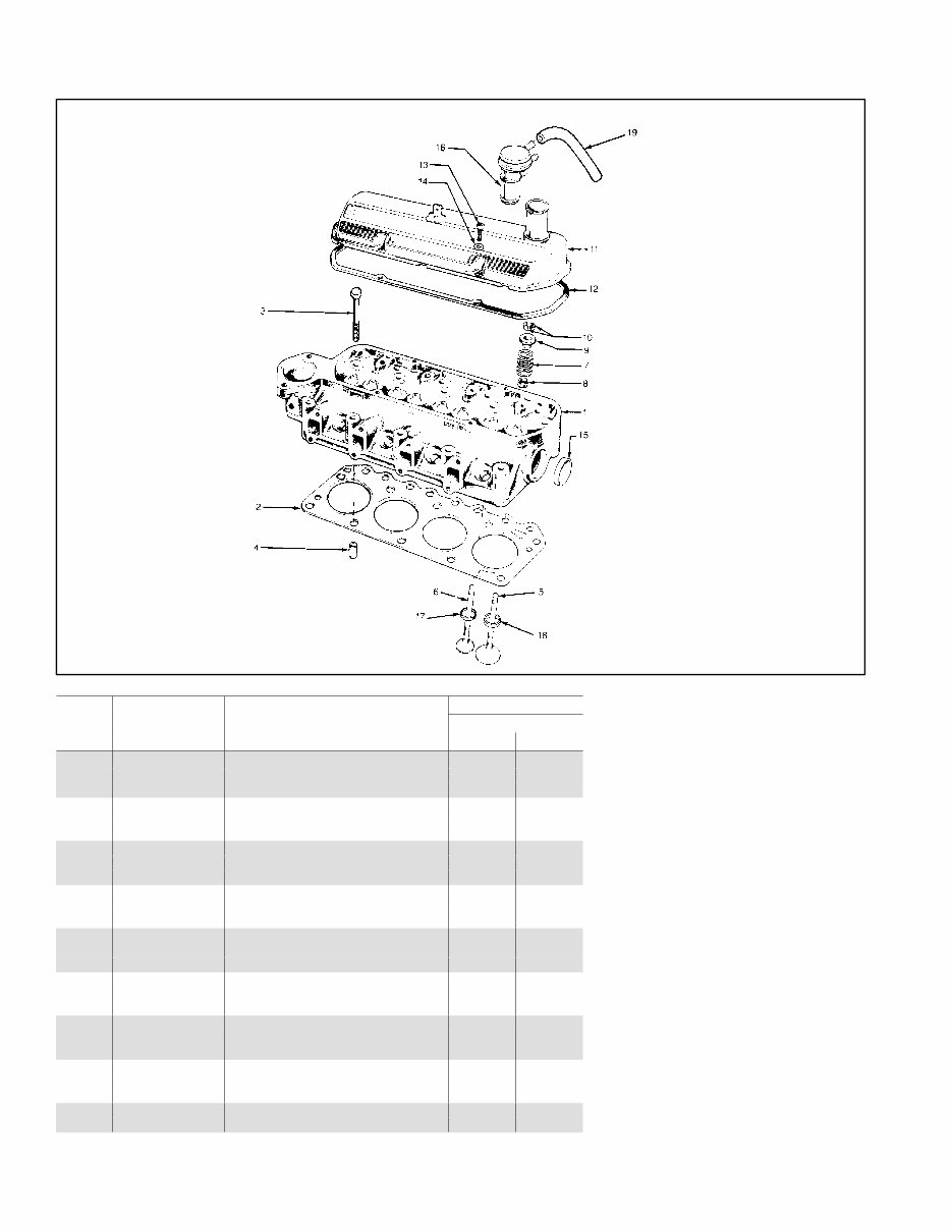
Cylinder Head and Valves
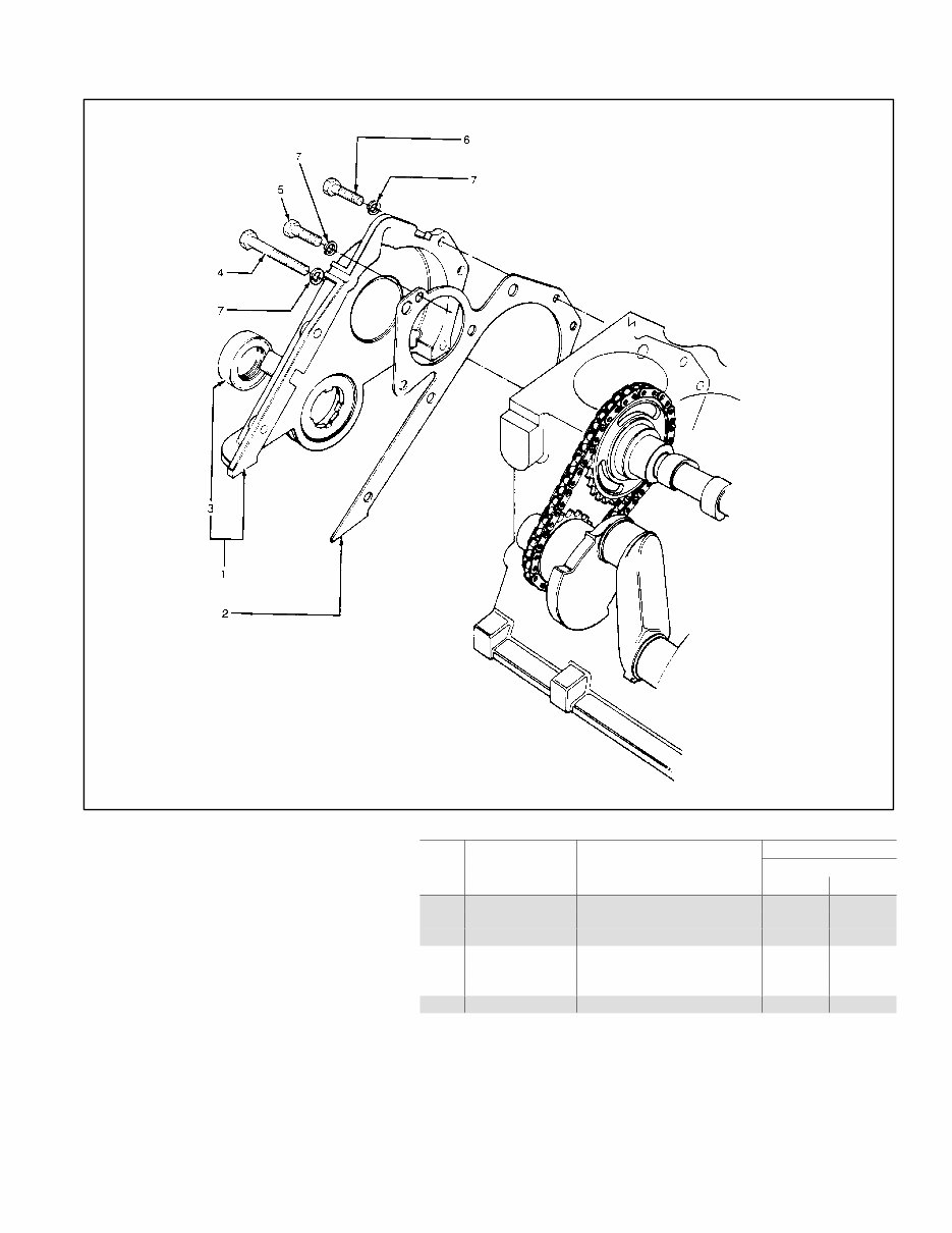
Front Cover Assembly
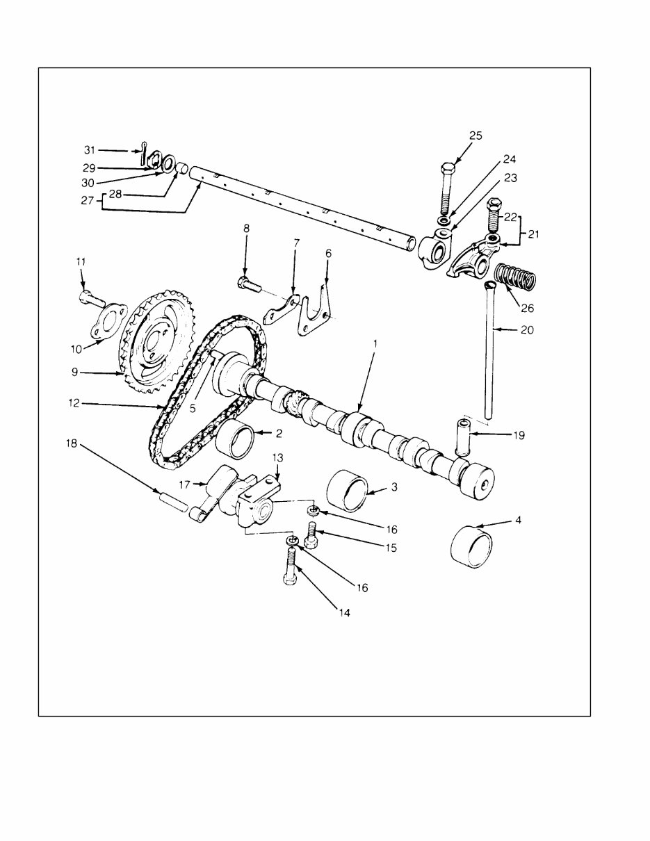
Camshaft and Valve Control
Crankshaft and Piston
Flywheel and Clutch
Oil Pump and Pan
Fan and Water Pump
Intake Manifold
Ignition Module and Spark Plugs
Air Intake
Fuel System
Cooling System
Engine
Nameplate and Decals
Oil Pressure Switches
Skid and Plant Mounting
Water Temperature Switches
Starter
Generator and Mounting
Controller and Mounting
Literature
Accessories
Appendix A: Abbreviations
Appendix B: Common Hardware Application Guidelines
Appendix C: General Torque Specifications
Appendix D: Common Hardware Identification
Appendix E: Common Hardware List
Language: English
This manual is crafted for ease of use and portability between different work areas. Whether you prefer to use it alongside your repair work station or reference a hard copy while performing maintenance, the manual is organized to empower mechanics with the information needed for efficient and effective repairs. It is an excellent tool for mechanics who value quick access to essential repair data while working on-site.