

Kohler 8-10kW Service Parts Catalog
What's Included?
Fast Download Speeds
Online & Offline Access
Access PDF Contents & Bookmarks
Full Search Facility
Print one or all pages of your manual
Marine Generator Sets
Models:
8CCFOZ/9CCOZ
8EFOZ/9EOZ
9EFOZ/10EOZ
TP-5587 3/00c
Service Parts

Table of Contents
Table of Contents
Description Page Description Page
Introduction 1 ..........................................
Numbering System Significance 1 ........................
Illustrations 1 ..........................................
How to Find Part Numbers 1 .............................
Hardware References 1 .................................
Specification Number Index 2 ............................
Group 1: Cylinder Block 4 ...............................
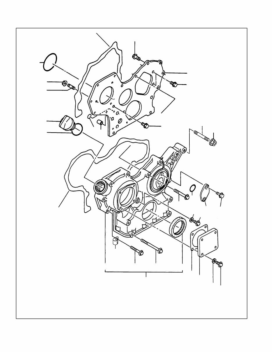
Group 2: Gear Housing 6 ...............................
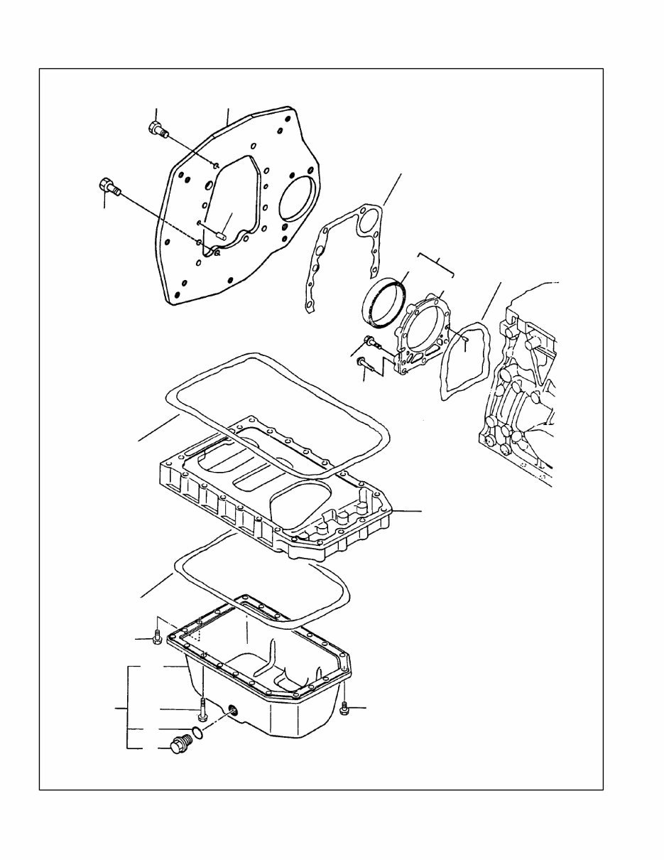
Group 3: Flywheel Housing & Oil Sump 8 .................
Group 4: Cylinder Head 10 ..............................
Group 5: Intake Manifold 12 .............................
Group 6: Camshaft 13 ..................................
Group 7: Crankshaft, Flywheel, & Pistons 14 ...............
Group 8: Lube Oil System 16 ............................
Group 9: Cooling Water System 17 .......................
Group 10: Fuel Injection Pump 18 ........................
Group 11: Fuel Injection Lines 20 ........................
Group 12: Fuel Line & Filter 22 ..........................
Group 13: Governor 26 .................................
Group 14: Starting Motor 30 .............................
Group 15: Gasket Set 32 ................................
Group 101: Air Intake 34 ................................
Group 103: Fuel System 35 .............................
Group 104: Cooling System 36 ..........................
Group 105: Engine 40 ..................................
Group 107: Nameplate and Decals 42 ....................
Group 109: Skid and Plant Mounting 43 ...................
Group 201: Generator and Mounting 44 ...................
Group 301: Controller and Mounting 46 ...................
Group 501: Housing 48 .................................
Group 701: Literature 48 ................................
Paint and Miscellaneous Parts 48 .........................
Parts List: Accessories 49 ...............................
Appendix A. Abbreviations A-1 ..........................
Appendix B. Common Hardware Application Guidelines A-3 .
Appendix C. General Torque Specifications A-4 ............
Appendix D. Common Hardware Identification A-5 ..........
Appendix E. Common Hardware List A-6 ..................

1 TP-5587 3/00
Introduction
This manual lists service replacement parts for 8--10 kW
generator sets.
At the time of print this manual applied to the generator
set specification (spec) numbers listed in the
Specification Number Index. On occasion this manual
may apply to specs not listed in the Specification
Number Index.
Information in this publication represents data available
at the time of print. Kohler Co. reserves the right to
change this publication and the products represented
without notice and without any obligation or liability
whatsoever.
This manual includes the following main sections:
Table of Contents. Lists the sections of the manual.
Introduction (and other information sections).
Contains introductory material about part numbers,
illustrations, and hardware.
Index. Lists the generator set specs and groups.
Group Parts Lists. List the part numbers of parts in the
groups.
Kit Sections. List modules and accessories and their
parts.
Appendices. Include Abbreviations, Common
Hardware Application Guidelines, General Torque
Specifications, Common Hardware Identification, and
Common Hardware List.
x:in:004:002
Numbering System Significance
This manual uses the following numbering systems:
Specification Number. A six-digit number with a PA-
prefix. The Specification Number Index does not show
the prefix. Spec numbers break down into groups.
Group Number. A unique number representing a parts
group needed to assemble a generator set function. For
example, Group 101 is the Air Intake group.
Variation or Module Number. A group might have
several variations. Each variation performs the same
function with different parts lists. For example, a 50 Hz
generator alternator and 60 Hz generator alternator
both perform the same function, however, with different
parts. Each difference requires a group variation or
module number.
Part Number. The part number identifies an individual
assembly, subassembly, component, or accessory kit.
x:in:004:003
Illustrations
Illustrations (or exploded-view drawings) best
representing the widest range of variations accompany
most groups in this manual. Illustrations do not depict all
details and may not show all parts. Do not use
illustrations for assembly or disassembly instructions.
x:in:004:004
How to Find Part Numbers
Use the following steps to locate a service replacement
part.
1. Locate the generator set nameplate to identify the
generator set spec number .
2. Locate a second generator set nameplate listing
accessories to identify installed modules. On
some models the accessory nameplate is mounted
inside the generator junction box.
3. Turn to the Specification Number Index. The
first column lists the generator set spec numbers.
The headings identify the groups of parts that make
up the generator set.
4. Identify the group most likely to include the
service part number.
5. Find the group variation number at the
intersection of the spec number row and the group
column. Note the variation number.
6. Page forward to locate the group identified in
step 4 or find the appropriate page in the Table of
Contents.
7. Find the part on the illustration and note the item
number of the part or find the part description in
the parts list.
8. Select the part number that corresponds to
your group variation. The first column lists the
illustration item number. Find the variation
identified in the Specification Number Index or the
module number found on the generator set
nameplate in the appropriate column on the right
side of the parts list table. Find the quantity used at
the intersection of the item number row and the
variation column. A blank space at the intersection
means the variation/module does not use that part
number.
x:in:004:005
Hardware References
Many common hardware items do not appear in parts
manuals or will appear as common hardware entries. A
common hardware entry lists the size of the hardware.
For example, an item that appears as “Hardware,
3/8-16” in the text means that the piece is 3/8-16 size.
Obtain common hardware locally or, if contacting the
factory, use the Common Hardware List in the appendix
to identify the common hardware part number and
specifications. See Common Hardware Application
Guidelines in the appendix for mating hardware
instructions.
Some hardware items require a specific size or some
other characteristic. In that case, use the part number
listed in the text.
When replacing hardware, do not substitute inferior
grade hardware. Replacement hardware grade should
be equal to or better than the grade of the
manufacturer’s original hardware. Use the Common
Hardware List in the appendix to identify the common
hardware hardness.
x:in:004:006
2
TP-5587 3/00
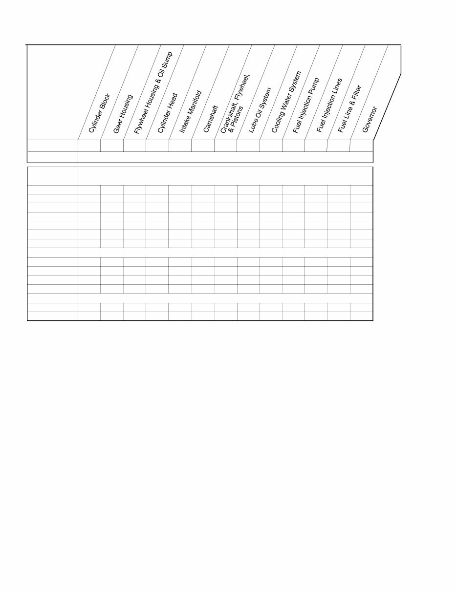
Specification Number Index
Group No.. 1 2 3 4 5 6 7 8 9 10 11 12 13
Spec No. VARIATION NUMBER
Group Title
8CCFOZ/
9CCOZ
126117 1 1 1 1 1 1 1 1 1 1 1 1 1
126123 1 1 1 1 1 1 1 1 1 1 1 1 1
126135 1 1 1 1 1 1 1 1 1 1 1 1 1
126140 2 2 2 2 2 1 2 2 2 2 2 2 2
126142 2 2 2 2 2 1 2 2 2 2 2 2 2
126144 1 1 1 1 1 1 1 1 1 1 1 1 1
126146 1 1 1 1 1 1 1 1 1 1 1 1 1
8EFOZ/9EOZ
126168 2 2 2 2 2 1 2 2 2 2 2 2 2
126169 2 2 2 2 2 1 2 2 2 2 2 2 2
126171 2 2 2 2 2 1 2 2 3 2 2 4 3
126179 2 2 2 2 2 1 2 2 2 2 2 2 2
9EFOZ/10EOZ
126195 3 3 2 3 2 1 3 2 2 3 4 5 2
126196 3 3 2 3 2 1 3 2 3 3 4 6 3
3 TP-5587 3/00
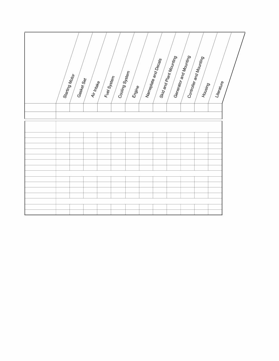
Specification Number Index
Group No. 14 15 101 103 104 105 107 109 201 301 501 701
Spec No. VARIATION NUMBER
Group Title
8CCFOZ/
9CCOZ
126117 1 1 2 2 6 19 7 8 19 23 — 8
126123 1 1 2 2 9 24 7 8 19 23 — 8
126135 1 1 2 2 9 24 7 8 19 28 3 8
126140 1 2 3 6 13 29 11 8 19 34 — 12
126142 1 2 3 6 14 30 11 8 19 35 7 12
126144 1 1 2 6 6 19 7 8 19 23 — 8
126146 1 1 2 6 9 24 7 8 19 28 3 8
8EFOZ/9EOZ
126168 1 2 3 6 13 29 11 8 27 34 — 19
126169 1 2 3 6 14 30 11 8 27 35 13 19
126171 2 2 3 9 16 34 11 8 27 41 — 19
126179 1 2 3 6 14 30 11 8 27 35 10 12
9EFOZ/10EOZ
126195 3 3 3 6 13 38 11 8 27 34 — 19
129196 4 3 3 9 16 39 11 8 27 41 — 19
4
TP-5587 3/00
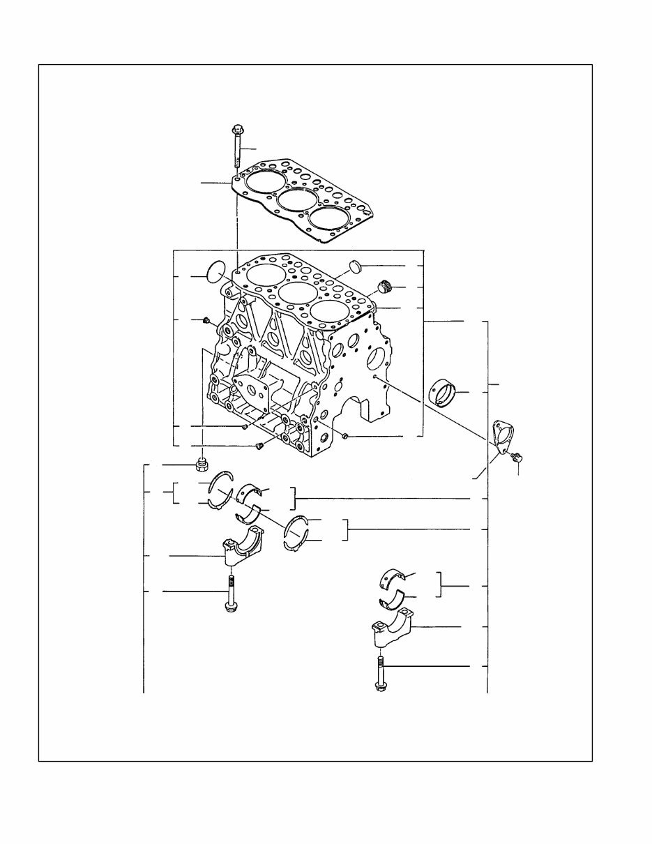
Group 1: Cylinder Block
1
2
3
4
5
6
7
8
9
10
11
12
13
14
15
16
17
18
19
20
21
22
23
17
18
12
13
16
See Group 6
558701
5

5
TP-5587 3/00
Group 1: Cylinder Block
Quantity
Part Variation Number
Item Number Description 1 2 3
1 229806 Block assembly, cylinder (includes items 2-20) 1
1 225441 Block assembly, cylinder (includes items 2-20) 1
1 GM13811 Block assembly, cylinder (includes items 2-20) 1
2 X Block assembly, cylinder 1 1
3 X Block, cylinder 1 1
4 252566 Plug 1 1 1
5 252771 Plug, PT 1/4 2 2 2
6 256515 Plug, PT 1/8, screw 1 1
6 GM13812 Plug, PT 1/8, screw 1
7 225827 Plug 50 1 1 1
8 252728 Plug 12 2 2 2
9 252731 Plug 30 6 6 6
10 X Bearing cap 1 1
11 X Bearing cap 3 3
12 225703 Bolt, bearing cap 8 8 8
13 229801 Main bearing 4
13 225832 Main bearing 4 4
13 225709 Main bearing undersize 0.25 4 4 4
14 X Main bearing 4 4
15 X Main bearing 4 4
16 229802 Bearing, thrust 2
16 225833 Bearing, thrust 2 2
16 225710 Bearing, thrust 0.25 oversize 2 2 2
17 X Bearing, thrust 2 2
18 X Bearing, thrust 2 2
19 252933 Bush, camshaft 1 1 1
20 256518 Plug 12, hex. 2 2
20 252771 Plug, PT 1/4 1
21 252696 Bolt, M8 x 16 plated 2
21 225818 Bolt, M8 x 14 plated 2 2
22 225705 Bolt, cylinder head 14 14 14
23 GM33837 Gasket, cylinder head 1
23 225399 Gasket, cylinder head 1
23 GM33836 Gasket, cylinder head 1
X Item not sold separately
6
TP-5587 3/00
Group 2: Gear Housing
1
2
3
4
5
6
7
8
9
10
11
12
13
14
15
16
17
18
19
20
21
22
23
1A
13
13
24
24
558701
25
26
27

7
TP-5587 3/00
Group 2: Gear Housing
Quantity
Part Variation Number
Item Number Description 1 2 3
1 229799 Housing assy., gear 1 1 1
1A X Housing, gear 1 1 1
2 252931 Seal, oil 1 1 1
3 252409 Stud, M8 x 22 3 3 3
4 250837 Cap, lub. oil supply 1 1 1
5 252861 Flange, gear housing 1 1 1
6 256531 Cover 1 1 1
7 252085 Gasket 1 1 1
8 252932 Pipe, knock 2 2 2
9 252764 O-ring, fuel injection pump 1 1 1
10 250981 O-ring 2 2 2
11 252684 O-ring 1 1 1
12 252695 Bolt, M8 x 12 plated 4 4 4
13 252696 Bolt, M8 x 16 plated 4 4 4
14 252703 Bolt, M8 x 45 plated 6 6 6
15 256798 Bolt, M8 x 55 plated 3 3 3
16 256799 Bolt, M8 x 85 plated 4 4 4
17 252723 Nut, M8 3 3 3
18 252734 Seal, washer 8 4 4 4
19 252697 Bolt, M8 x 20 plated 2 2 2
20 252734 Seal, washer 8 1 1 1
21 252750 Cover, blind 1 1 1
22 256796 O-ring 1 1 1
23 225816 Bolt, M6 x 12 plated 2 2
23 252693 Bolt, M6 x 16 plated 2
24 252998 Liquid gasket AR AR AR
25 252808 Retainer 1 1
26 252756 Stud 1 1
26 GM13815 Stud 1
27 229772 Nut, M10 1 1
X Item not sold separately
8
TP-5587 3/00
Group 3: Flywheel Housing & Oil Sump
1
2
3
4
5
6
7
8
9
10
11
12
13
14
15
16
17
18
18
18
10
18
558703
You're Reading a Preview
What's Included?
Fast Download Speeds
Online & Offline Access
Access PDF Contents & Bookmarks
Full Search Facility
Print one or all pages of your manual
$32.99
Viewed 91 Times Today


Secure transaction
What's Included?
Fast Download Speeds
Online & Offline Access
Access PDF Contents & Bookmarks
Full Search Facility
Print one or all pages of your manual
$32.99
This comprehensive manual provides a complete listing of generator service replacement parts for Kohler and Yanmar Engine Marine Generator Sets. Designed for DIY repair enthusiasts, it offers practical information to help you identify, locate, and order the necessary components for your maintenance projects.
- Table of Contents: Organized listing of all sections.
- Introduction and Information Sections: Offers background material, part number details, illustrations, and hardware information.
- Specification Number Index: Details generator set specifications and groups.
- Group Parts Lists: Displays part numbers organized by groups.
- Kit Sections: Provides lists of modules, accessories, and their corresponding parts.
- Appendices: Contains abbreviations, common hardware application guidelines, general torque specifications, hardware identification, and comprehensive hardware lists.
Models Covered:
- Kohler 8CCFOZ / 9CCOZ
- Kohler 8EFOZ / 9EOZ
- Kohler 9EFOZ / 10EOZ
Manual Contents:
- Introduction
- Numbering System Significance
- Illustrations
- How to Find Part Numbers
- Hardware References
- Specification Number Index:
- Cylinder Block
- Gear Housing
- Flywheel Housing & Oil Sump
- Cylinder Head
- Intake Manifold
- Camshaft
- Crankshaft, Flywheel, & Pistons
- Lube Oil System
- Cooling Water System
- Fuel Injection Pump
- Fuel Injection Lines
- Fuel Line & Filter
- Governor
- Starting Motor
- Gasket Set
- Air Intake
- Fuel System
- Cooling System
- Engine
- Nameplate and Decals
- Skid and Plant Mounting
- Generator and Mounting
- Controller and Mounting
- Housing
- Literature
- Paint and Miscellaneous Parts
- Parts List: Accessories
- Appendix A. Abbreviations
- Appendix B. Common Hardware Application Guidelines
- Appendix C. General Torque Specifications
- Appendix D. Common Hardware Identification
- Appendix E. Common Hardware List
This manual is extremely portable; you can easily reference the content on various devices or print the pages you need. Many professionals in the repair industry find it invaluable to have quick access to this detailed information while working on site.


