Generac 4702 4703 4705 4706 4707 Diagnostic Service Repair Manual
What's Included?
Lifetime Access
Fast Download Speeds
Online & Offline Access
Access PDF Contents & Bookmarks
Full Search Facility
Print one or all pages of your manual
Owner’s Manual Air-cooled Recreational Vehicle Generators QUIETPACT ® 55, 65 and 75 • Models: 004702-0, 004703-0 004704-0, 004705-0 004706-0, & 004707-0 This manual should remain with the unit.
INTRODUCTION READ THIS MANUAL THOROUGHLY If any portion of this manual is not understood, con- tact the nearest Authorized Service Dealer for start- ing, operating and servicing procedures. Throughout this publication, and on tags and decals affixed to the generator, DANGER, WARNING, CAUTION and NOTE blocks are used to alert person- nel to special instructions about a particular opera- tion that may be hazardous if performed incorrectly or carelessly. Observe them carefully. Their defini- tions are as follows: DANGER After this heading, read instructions that, if not strictly complied with, will result in personal inju- ry, including death, and property damage. After this heading, read instructions that, if not strictly complied with, may result in personal inju- ry or property damage. After this heading, read instructions that, if not strictly complied with, could result in damage to equipment and/or property. NOTE: After this heading, read explanatory statements that require special emphasis. These safety warnings cannot eliminate the hazards that they indicate. Common sense and strict compli- ance with the special instructions while performing the service are essential to preventing accidents. Four commonly used safety symbols accompany the Danger, Warning and Caution blocks. The type of information each indicates follows: This symbol points out important safety infor- mation that, if not followed, could endanger personal safety and/or property of others. This symbol points out potential explosion hazard. This symbol points out potential fire hazard. This symbol points out potential electrical shock hazard. The operator (driver) is responsible for proper and safe use of the vehicle and its equipment, and the safety of all vehicle occupants. We strongly recom- mend that the operator read this manual and thor- oughly understand all instructions before using this equipment. We also strongly recommend instructing other occupants in the vehicle to properly start and operate the generator. This prepares them if they need to operate the equipment in an emergency. CONTENTS This manual contains pertinent owner’s information, including warranty, electrical diagrams, exploded views and lists of repair parts for generator model numbers 004702-0, 004703-0, 004704-0, 004705-0, 004706-0, and 004707-0. In addition, the latter por- tion of this manual contains information necessary for the proper installation of these generators. OPERATION AND MAINTENANCE It is the operator's responsibility to perform all safety checks, to make sure that all maintenance for safe operation is performed promptly, and to have the equipment checked periodically by an Authorized Service Dealer. Normal maintenance service and replacement of parts are the responsibility of the owner/operator and, as such, are not considered defects in materials or workmanship within the terms of the warranty. Individual operating habits and usage contribute to the need for maintenance service. Proper maintenance and care of the generator ensures a minimum number of problems and keep operating expenses at a minimum. See an Authorized Service Dealer for service aids and accessories. HOW TO OBTAIN SERVICE When the generator requires servicing or repairs, simply contact an Authorized Service Dealer for assistance. Service technicians are factory-trained and are capable of handling all service needs. When contacting an Authorized Service Dealer about parts and service, always supply the complete model number and serial number of the unit as given on its data decal, which is located on the generator. Model No. ____________ Serial No.______________ AUTHORIZED SERVICE DEALER LOCATION To locate the nearest AUTHORIZED SERVICE DEALER, please call this number: 1-800-333-1322 ONLY DEALER LOCATION INFORMATION CAN BE OBTAINED AT THIS NUMBER; or locate us on the web at www.generac.com.
Table of Contents Recreational Vehicle Generators 1 Part I — Operating Instructions Introduction ...................................... Inside Front Cover Read This Manual Thoroughly ................................ IFC Contents ................................................................. IFC Operation and Maintenance .................................... IFC How to Obtain Service ............................................ IFC Authorized Service Dealer Locator Number .............. IFC Safety Rules ...................................................................... 2 Section 1 – General Information ................................. 4 1.1 Generator Identification ...................................... 4 1.2 Generator Applicability ....................................... 5 1.3 Installation .......................................................... 5 1.4 Safety .................................................................. 5 1.5 Generator AC Connection System ....................... 5 1.6 Specifications ...................................................... 6 Section 2 – Operation .................................................... 7 2.1 Generator Control Panel...................................... 7 2.2 Optional Remote Start/Stop Panel ....................... 8 2.3 Automatic Choke ................................................. 8 2.4 Before Starting the Engine .................................. 8 2.5 Starting the Generator ........................................ 9 2.6 Stopping the Generator ....................................... 9 2.7 Applying Loads to Generator............................... 9 2.8 Protection Systems ............................................ 10 Section 3 – Maintenance ............................................. 11 3.1 Checking the Engine Oil Level ........................... 11 3.2 Changing the Engine Oil and/or Oil Filter ......... 12 3.3 Maintaining the Engine Air Cleaner ................... 12 3.4 Checking the Engine Spark Plug ....................... 13 3.5 Fuel Filter (Gasoline Only)................................. 13 3.6 Clean Spark Arrestor ........................................ 13 3.7 Cleaning the Generator ..................................... 14 3.8 Battery Maintenance .......................................... 14 3.9 Major Service Manual........................................ 15 3.10 Drive Belt .......................................................... 15 3.11 Exercising the Generator................................... 15 3.12 Out of Service Procedure................................... 15 3.13 RV Generator Service Interval ........................... 15 Section 4 – Notes .......................................................... 16 Part II — Installation Instructions .............. 17 Safety Rules .................................................................... 18 Section 5 — General Information .............................. 20 5.1 Purpose and Scope of the Installation Instructions ....................................................... 20 5.2 Safety ................................................................ 20 5.3 Standards Booklets ........................................... 20 5.4 Equipment Description ..................................... 20 5.5 Generator Engine Operating Speed ................... 20 5.6 Generator AC Connection System ..................... 20 Major Features and Dimensions ........................ 21 Section 6 — Installation ............................................... 22 6.1 Location and Support ....................................... 22 6.2 Generator Compartments ................................. 23 6.3 Cooling and Ventilating Air ................................ 25 6.4 Gasoline Fuel System ........................................ 26 6.5 LP Gas Fuel System .......................................... 27 6.6 Exhaust System................................................. 29 6.7 Electrical Connections....................................... 30 6.8 Battery Installation ............................................ 32 6.9 Optional Accessories ......................................... 34 Section 7 — Post Installation ...................................... 34 7.1 Post Installation Tests ....................................... 34 7.2 Before Initial Start-up........................................ 34 7.3 Initial Start ........................................................ 34 7.4 Testing Under Load ........................................... 35 7.5 Installation Checklist......................................... 35 Section 8 – Troubleshooting ....................................... 36 8.1 Troubleshooting Guide ...................................... 36 Section 9 – Notes .......................................................... 37 Section 10 – Electrical Data ........................................ 38 Section 11 – Exploded Views and Parts Lists......... 40 Section 12 – Warranty .................................................. 52
2 Study these SAFETY RULES carefully before install- ing, operating or servicing this equipment. Become familiar with this manual and with the unit. The gen- erator can operate safely, efficiently and reliably only if it is properly installed, operated and maintained. Many accidents are caused by failing to follow simple and fundamental rules or precautions. The manufacturer cannot anticipate every possible circumstance that might involve a hazard. The warn- ings in this manual, and on tags and decals affixed to the unit, are, therefore, not all-inclusive. If using a procedure, work method or operating technique the manufacturer does not specifically recommend, ensure that it is safe for others. Also make sure the procedure, work method or operating technique that chosen does not render the generator unsafe. DANGER Despite the safe design of this generator, operating this equipment imprudently, neglect- ing its maintenance or being careless can cause possible injury or death. Permit only responsible and capable persons to operate or maintain this equipment. Potentially lethal voltages are generated by these machines. Ensure all steps are taken to render the machine safe before attempting to work on the generator. Parts of the generator are rotating and/or hot during operation. Exercise care near running generators. GENERAL HAZARDS • For safety reasons, the manufacturer recommends that the installation, initial start-up and main- tenance of this equipment is carried out by an Authorized Service Dealer. • The generator engine releases DEADLY carbon monoxide gas through its exhaust system. This dangerous gas, if breathed in sufficient concentra- tions, can cause unconsciousness or even death. Never operate the generator set with the vehicle inside any garage or other enclosed area. DO NOT OPERATE THE GENERATOR IF THE EXHAUST SYSTEM IS LEAKING OR HAS BEEN DAMAGED. SYMPTOMS OF CARBON MONOXIDE POISONING ARE (a) inability to think coherently, (b) nausea, (c) vomiting, (d) twitching muscles, (e) throbbing temples, (f) dizziness, (g) headaches, (h) weak- ness, and (i) sleepiness. IF EXPERIENCING ANY OF THESE SYMPTOMS, MOVE INTO FRESH AIR IMMEDIATELY. IF SYMPTOMS PERSIST, GET MEDICAL HELP. Shut down the generator and do not operate it until it has been inspected and repaired. • Never sleep in the vehicle while the genset is run- ning unless the vehicle has a working carbon monoxide detector. The exhaust system must be installed in accordance with the genset installation manual. Make sure there is ample fresh air when operating the genset in a confined area. • Keep hands, feet, clothing, etc., away from drive belts, fans, and other moving or hot parts. Never remove any drive belt or fan guard while the unit is operating. • Adequate, unobstructed flow of cooling and ven- tilating air is critical to correct generator opera- tion and is required to expel toxic fumes and fuel vapors from the generator compartment. Without sufficient cooling airflow, the engine/generator quickly overheats, which causes serious damage to the generator. Do not alter the installation or permit even partial blockage of ventilation provi- sions, as this can seriously affect safe operation of the generator. • When working on this equipment, remain alert at all times. Never work on the equipment when physically or mentally fatigued. • Inspect the generator regularly, and contact the nearest Authorized Service Dealer immediately for parts needing repair or replacement. Safety Rules Recreational Vehicle Generators SAVE THESE INSTRUCTIONS – The manufacturer suggests that these rules for safe operation be copied and posted in potential hazard areas of the recreational vehicle. Safety should be stressed to all operators and potential operators of this equipment. The engine exhaust from this product contains chemicals known to the state of California to cause cancer, birth defects or other reproductive harm. WARNING: This product contains or emits chemicals known to the state of California to cause cancer, birth defects or other reproductive harm. WARNING:
3 • Before performing any maintenance on the gen- erator, disconnect its battery cables to prevent accidental start up. Disconnect the cable from the battery post indicated by a NEGATIVE, NEG or (–) first. Reconnect that cable last. • Never use the generator or any of its parts as a step. Stepping on the unit can stress and break parts, and may result in dangerous operating con- ditions from leaking exhaust gases, fuel leakage, oil leakage, etc. ELECTRICAL HAZARDS • The generator covered by this manual produces dangerous electrical voltages and can cause fatal electrical shock. Avoid contact with bare wires, ter- minals, connections, etc., while the unit is running. Ensure all appropriate covers, guards and barriers are in place before operating the generator. If work must be done around an operating unit, stand on an insulated, dry surface to reduce shock hazard. • Do not handle any kind of electrical device while standing in water, while barefoot, or while hands or feet are wet. DANGEROUS ELECTRICAL SHOCK MAY RESULT. • During installation onto the vehicle, have the generator properly grounded (bonded) either by solid mounting to the vehicle frame or chassis, or by means of an approved bonding conductor. DO NOT disconnect the bonding conductor, if so equipped. DO NOT reconnect the bonding conduc- tor to any generator part that might be removed or disassembled during routine maintenance. If the grounding conductor must be replaced, use only a flexible conductor that is of No. 8 American Wire Gauge (AWG) copper wire minimum. • In case of accident caused by electric shock, imme- diately shut down the source of electrical power. If this is not possible, attempt to free the victim from the live conductor. AVOID DIRECT CONTACT WITH THE VICTIM. Use a nonconducting imple- ment, such as a rope or board, to free the victim from the live conductor. If the victim is uncon- scious, apply first aid and get immediate medical help. • Never wear jewelry when working on this equip- ment. Jewelry can conduct electricity resulting in electric shock, or may get caught in moving com- ponents causing injury. FIRE HAZARDS • For fire safety, the generator must be installed and maintained properly. Installation always must comply with applicable codes, standards, laws and regulations. Adhere strictly to local, state and national electrical and building codes. Comply with regulations the Occupational Safety and Health Administration (OSHA) has established. Also, ensure that the generator is installed in accordance with the manufacturer’s instructions and recommendations. Following proper installa- tion, do nothing that might alter a safe installation and render the unit in noncompliance with the aforementioned codes, standards, laws and regula- tions. • Keep a fire extinguisher in the vehicle at all times. Extinguishers rated “ABC” by the National Fire Protection Association are appropriate for use on the recreational vehicle generator electrical sys- tem. Keep the extinguisher properly charged and be familiar with its use. If there are any questions pertaining to fire extinguishers, consult the local fire department. EXPLOSION HAZARDS • Do not smoke around the generator. Wipe up any fuel or oil spills immediately. Ensure that no com- bustible materials are left in the generator com- partment, or on or near the generator, as FIRE or EXPLOSION may result. Keep the area surround- ing the generator clean and free from debris. • Gasoline is extremely FLAMMABLE and its vapors are EXPLOSIVE. Do not permit smoking, open flame, sparks or any source of heat in the vicinity while handling gasoline. Comply with all laws gov- erning the storage and handling of gasoline. • This generator may use liquid propane (LP) gas as a fuel. LP gas is highly EXPLOSIVE. The gas is heavier than air and tends to settle in low areas where even the slightest spark can ignite the gas and cause an explosion. Safety Rules Recreational Vehicle Generators
4 Section 1 – General Information Recreational Vehicle Generators Please record the following information from the generator DATA DECAL or information decal. 1. Model Number _____________________ 2. Serial Number __________________ 3. kW Rating _________________________ 4. Rated Voltage __________________ 5. Phase ______________________________ 6. Hertz __________________________ 7 9, 18 6 PANEL 17 13 12 1 11, 15 (Behind Access Panel) 10 5 2 3 4 14 8 16 19 1.1 GENERATOR IDENTIFICATION REFERENCE NUMBER IDENTIFICATION 1. Generator Air Intake Screen 2. Data Plate 3. Engine Start/Stop Switch 4. 7.5 amp Fuse 5. Circuit Breaker 6. Optional Remote Panel Receptacle 7. Generator AC Output Leads 8. Starter Contactor 9. Fuel Inlet 10. Fuel Primer Switch 11. Fuel Pump (Behind access panel.) 12. Oil Filter 13. Oil Drain Plug 14. Oil Dipstick and Filler Tube 15. Air Filter (Behind access panel.) 16. Spark Plugs 17. Exhaust Outlet 18. Fuel Filter 19. LP Fuel Inlet
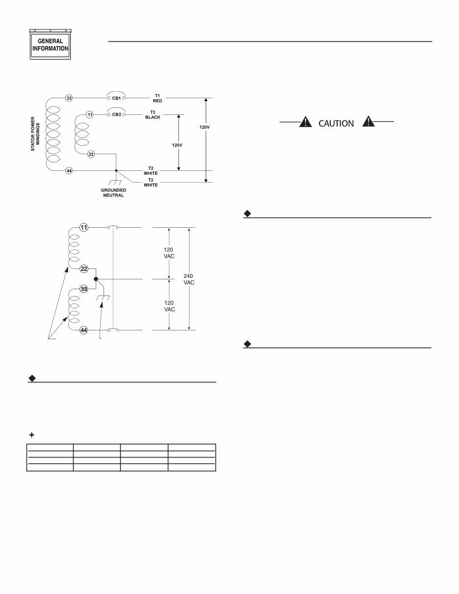
5 Section 1 – General Information Recreational Vehicle Generators 1.2 GENERATOR APPLICABILITY These generators have been designed and manufac- tured for supplying electrical power for recreational vehicles. DO NOT modify the generator or use it for any application other than for what it was designed. If there are any questions pertaining to its applica- tion, write or call the factory. Do not use the unit until advised by competent authority. DANGER For fire safety, the generator must have been properly installed in compliance with ANSI 119.2-1975/NFPA 501C-1974, “Standard for Recreational Vehicles, Part III – Installation of Electrical Systems.” The generator also must have been installed in strict compliance with the manufacturer’s detailed installation instructions. After installation, do nothing that might render the unit in noncompliance with such codes, stan- dards and instructions. Use the generator set to supply electrical power for operating one of the following electrical loads: • QUIETPACT 55G & LP: 120 and/or 240 volts, single phase, 60 Hz electrical loads. These loads can require up to 5500 watts (5.5 kW) of total power, but cannot exceed 45.8 AC amperes of cur- rent at 120 volts or exceed 22.9 AC amperes at 240 volts. • QUIETPACT 65G & LP: 120 and/or 240 volts, sin- gle phase, 60 Hz electrical loads. These loads can require up to 6500 watts (6.5 kW) of total power, but cannot exceed 54.1 AC amperes of current at 120 volts or exceed 27 AC amperes at 240 volts. • QUIETPACT 75G & LP: 120 and/or 240 volts, single phase, 60 Hz electrical loads. These loads can require up to 7500 watts (7.5 kW) of total power, but cannot exceed 62.5 AC amperes of cur- rent at 120 volts or exceed 31.2 AC amperes at 240 volts. Do not overload the generator. Some installa- tions may require that electrical loads be alter- nated to avoid overloading. Applying exces- sively high electrical loads may damage the generator and may shorten its life. Add up the rated watts of all electrical lighting, appliance, tool and motor loads the generator will power at one time. This total should not be greater than the wattage capacity of the generator. If an electrical device nameplate gives only volts and amps, multiply volts times amps to obtain watts (volts x amps = watts). Some electric motors require more watts of power (or amps of cur- rent) for starting than for continuous operation. 1.3 INSTALLATION This Owner’s Manual has been prepared under the assumption that a competent, qualified technician installed the generator into a recreational vehicle. We also assume the installer complied with all applicable codes, standards and regulations pertaining to instal- lation. An INSTALLATION MANUAL was shipped with the generator. That Manual contains manufacturer’s instructions and recommendations for installing the unit into an industrial vehicle. After installation, installers should forward the Installation Manual to Owners/Operators for their information. Owners/Operators have the responsibility to make sure that nothing is done that might render the instal- lation unsafe or in non-compliance with applicable codes, standards and instructions. 1.4 SAFETY Before using the generator set, carefully read GENERAL SAFETY RULES inside the cover. Comply with these RULES to prevent accidents and damage to equipment and/or property. The manufacturer suggests copying and posting the GENERAL SAFETY RULES to potential operators of this equipment. 1.5 GENERATOR AC CONNECTION SYSTEM These air-cooled generator sets are equipped with dual stator AC power windings. These two stator windings supply electrical power to customer elec- trical loads by means of a dual 2-wire connection system. Generators may be installed to provide the following outputs: 1. 120 VAC loads only — one load with a maximum total wattage requirement equal to the generator’s rated power output (in watts), and 120V across the generator output terminals. Figure 1.1 shows the generator lead wire connections for 120VAC ONLY. 2. 120/240 VAC loads — one load with a maximum total wattage requirement equal to the generator’s rated power output, and 240V across the genera- tor output terminals; or two seperate loads, each with a maximum total wattage requirement equal to half of the generator’s rated power output (in watts), and 120V across the generator output ter- minals. Figure 1.2, shows the generator lead wire connections for 120/240 VAC loads. Also refer to section 2.1.4 Line Breakers for circuit breaker ratings. This procedure should be done by an Authorized Service Dealer or other qualified installer.
6 Section 1 – General Information Recreational Vehicle Generators Figure 1.1 – Connection for 120 Volts Only Figure 1.2 - Connection for 120/240 Volts T1 RED T2 WHITE T3 BLACK GROUNDED NEUTRAL STATOR WINDINGS CB1 CB2 1.6 SPECIFICATIONS 1.6.1 FUEL REQUIREMENTS (GASOLINE) This generator is equipped with a gasoline fuel system as standard equipment. Specific installations may provide either a separate fuel tank for the generator, or the generator may “share” the vehicle engine’s fuel tank. 1.6.1.1 Fuel Consumption (gph) NOTE Some installations using a “shared” fuel tank may have a generator fuel pickup tube that is shorter than the vehicle engine’s pickup tube. Such an arrangement causes the generator engine to “run out of gas” while adequate fuel for the vehicle remains in the tank. To reduce lead and carbon deposits use high qual- ity UNLEADED gasoline with the generator. Leaded REGULAR grade gasoline is an acceptable substitute. NOTE: Using unleaded gasoline contributes to longer engine valve life by reducing lead and carbon deposits. The manufacturer does not recommend using any gasoline containing alcohol (such as “gaso- hol”). If using any gasoline containing alcohol, it must not contain more than 10 percent ethanol, and it must be removed from the generator dur- ing storage. Do NOT use any gasoline containing methanol. If using gasoline with alcohol, inspect more frequently for fuel leaks and other abnor- malities. 1.6.2 ENGINE OIL REQUIREMENTS Use only high quality detergent oil rated with American Petroleum Institued (API) Classification SF, SG, SH or SJ. The recommended oil viscosity weights include the following: • During summer months (40 deg. F and higher), SAE 30 or SAE 10W-30 • During winter months (40 deg. F to -20 deg. F), SAE 5W-30 or SAE5W20 • DO NOT USE SAE 10W-40 Crankcase and oil filter capacity is approximately 1.8 L or 1.9 U.S. quarts. DO NOT use special additives. See Sections 3.1 and 3.2 for oil level check and filling procedures. 1.6.3 ENGINE SPECIFICATIONS Type of Engine..............................................................GT-760 Cooling Method ....................................................... Air-cooled Rated Horsepower ......................................... 27 at 3600 rpm Displacement.................................................................. 760cc Compression Ratio ..................................................... 8.6 to 1 Cylinder Block .........................Aluminum w/Cast Iron Sleeve Type of Governor .............................Mechanical, Fixed Speed Engine Governor Speed QUIETPACT 55 ..................................................... 2200 rpm QUIETPACT 65/75 ................................................ 2571 rpm Air Cleaner ....................... Paper Element w/Foam Precleaner Starter ....................................................... 12-volt DC Electric Ignition System ..................... Solid-state w/Flywheel Magneto Recommended Spark Plug Champion ................................................................ RC14YC AC.................................................................................. R45S Fram Autolite .....................................................................65 Spark Plug Gap...................................... 0.030 inch (0.8 mm) Recommended Min. Battery .......... 400 Cold Cranking Amps Model 10% Load 50% Load 100% Load QuietPact 55G 0.51 0.73 0.97 QuietPact 65G 0.51 0.76 1.07 QuietPact 75G 0.51 0.80 1.28
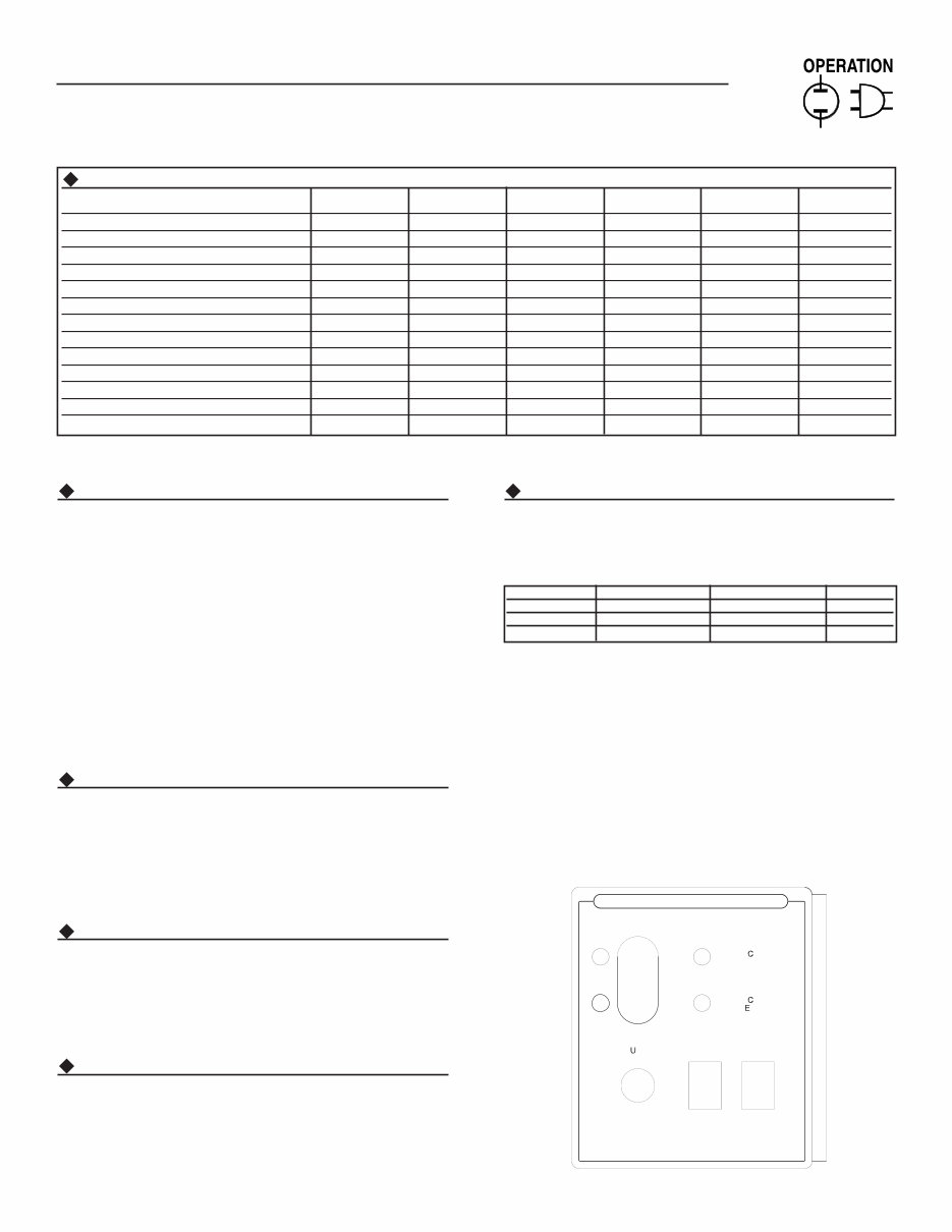
7 Section 2 – Operation Recreational Vehicle Generators 1.6.5 EMISSIONS COMPLIANCE PERIOD For nonhandled engines the Emissions Compliance Period referred to on the Emissions Compliance Label indicates the number of operating hours for which the engine has been shown to meet Federal emission requirements. • For engines less than 225 cc displacement, Category C=125 hours, B=250 hours, and A=500 hours. • For engines of 225 cc or more, Category C=250 hours, B=500 hours, and A=1000 hours. 2.1 GENERATOR CONTROL PANEL The following features are mounted on the generator control panel (Figure 2.1): 2.1.1 FUEL PRIMER Before starting a cold engine (if it has not been started in more than two weeks), press this switch for approximately ten seconds to bring fuel from the tank to the fuel pump. This rocker type switch springs back into its original position when it is released. 2.1.2 START/STOP SWITCH To crank and start the engine, hold this switch in the START position. Release the switch when the engine starts. To stop an operating engine, press and hold the switch in the STOP position until the engine shuts off. The switch center position is the RUN position. 2.1.3 7.5 AMP FUSE The fuse protects the engine’s DC control circuit against electrical overload. If the fuse element has melted open due to overloading, the engine cannot be cranked. If the fuse must be replaced, use only an identical 7.5 amp replacement fuse. 2.1.4 LINE BREAKERS Protects generator’s AC output circiut against over- load, i.e., prevents unit from exceeding wattage/ amperage capacity. The circuit breaker ratings are as follows: NOTE: If this generator has been reconnected for dual voltage AC output (120/240 volts), install line breakers having an amperage rating that is differ- ent than that stated above. The replacement line breakers consist of two separate breakers with a connecting piece between the breaker handles (so that both breakers will operate at the same time). If the unit is reconnected for dual voltage, it is no longer RVIA or CSA listed. Figure 2.1 – Typical Control Panel P R I M E S T O P S T A R T F U E L F S E 7 . 5 A 0E0580 REV. B CONTROL CENTER C I R U I T B R E A K E R B R A K E R C I R U I T PRESS PRIME SWITCH FOR 10 SECONDS BEFORE STARTING. WHEN STARTING, DO NOT PRESS START BUTTON LONGER THEN 15 SECONDS PER ATTEMPT. IF GENERATOR DOESNOT START. REMOVE AND INSPECT FUSE. (SEE OWNER'S MANUAL TROUBLE SHOOTING GUIDE.) 1.6.3 GENERATOR SPECIFICATIONS SERIES QP55G QP55LP QP65G QP65LP QP75G QP75LP Rotor RPM 3600 3600 3600 3600 3600 3600 Rotor Poles 2 2 2 2 2 2 Engine RPM 2200 2200 2571 2571 2571 2571 Rated Max. Continuous AC Output Watts* 5500 5500 6500 6500 7500 7500 Voltage* 120 120 120 120 120 120 Rated Max. Continuous Current Amps (240V) 45.8 (22.9) 45.8 (22.9) 54.1 (27.0) 54.1 (27.0) 62.5 (31.2) 62.5 (31.2) Phase 1 1 1 1 1 1 Frequency 60 Hertz 60 Hertz 60 Hertz 60 Hertz 60 Hertz 60 Hertz Battery Charging Current (Max.) 2 amps 2 amps 2 amps 2 amps 2 amps 2 amps Weight 326 lbs. 329 lbs. 328 lbs. 331 lbs. 330 lbs. 333 lbs. Length 33.7 in. 33.7 in. 33.7 in. 33.7 in. 33.7 in. 33.7 in. Width 22.2 in. 22.2 in. 22.2 in. 22.2 in. 22.2 in. 22.2 in. Height 19.6 in. 19.6 in. 19.6 in. 19.6 in. 19.6 in. 19.6 in. * All units are reconnectable to 120 and/or 240 volts, dual voltage output. Units are not listed per RVIA/ANSI when reconnected for dual voltage output Model Circuit Breaker 1 Circuit Breaker 2 240 Volt QuietPact 55 30A 20A 25A 2P QuietPact 65 30A 30A 30A 2P QuietPact 75 35A 35A 35A 2P
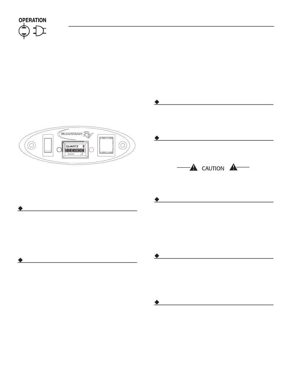
8 Section 2 – Operation Recreational Vehicle Generators 2.2 OPTIONAL REMOTE START/STOP PANEL A remote mounted Start/Stop Panel (Figure 2.2) is available that allows starting and stopping the gen- erator engine conveniently from inside the vehicle. The remote panel includes a Start/Stop switch, hour- meter, generator run lamp, a fuel prime switch, and a wire harness. Figure 2.2 — Optional Remote Panel (Part Numbers 0F0429 and 0F0430) PRIME FUEL STOP RUN 2.3 AUTOMATIC CHOKE This engine is equipped with an automatic choke that consists of two main components: a choke solenoid and prechoke. 2.3.1 CHOKE SOLENOID During engine cranking (Start/Stop switch at START), a solid-state choke module signals the choke sole- noid to activate and cycle (choke on/choke off) until the engine starts. The choke solenoid thus opens and closes the carburetor choke valve only when the engine is cranking. When the engine starts, the choke stops cycling. 2.3.2 PRECHOKE The choke system also has a temperature-sensitive metal strip that adjusts choke valve angle according to ambient temperatures (i.e., in cold ambient tem- peratures, choke valve closes more). Once the engine starts, an element heats the temperature-sensitive strip to a normal operating condition, opening the choke valve. This may take about three minutes in cooler weather. 2.4 BEFORE STARTING THE ENGINE NOTE: Instructions and information in this manual assume the generator has been properly installed, connected, serviced, tested and adjusted by a qualified installation technician or installation contractor. 2.4.1 INSTALLATION Generator installation must have been properly com- pleted so it complies with all applicable codes, stan- dards and regulations and with the manufacturer's recommendations. 2.4.2 ENGINE LUBRICATION Have the engine crankcase properly serviced with the recommended oil before starting. Refer to Section 1.6.3 and Sections 3.1 and 3.2 for oil servicing pro- cedures and recommendations. Any attempt to crank or start the engine before it has been properly serviced it with the recom- mended oil may result in an engine failure. 2.4.3 FUEL SUPPLY The engine must have an adequate supply of proper fuel to operate. Before starting it, check that suffi- cient fuel is available. NOTE: Depending on the installation, the generator may have either a separate fuel tank, or it may “share” the vehicle engine’s fuel tank. 2.4.4 COOLING AND VENTILATING AIR Air inlet and outlet openings in the generator com- partment must be open and unobstructed for con- tinued proper operation. Without sufficient cooling and ventilating airflow, the engine/generator quickly overheats, which causes it to shut down and may damage the generator. 2.4.5 ENGINE EXHAUST GAS Before starting the generator engine, be sure there is no way for exhaust gases to enter the vehicle interior and endanger people or animals. Close windows, doors and other openings in the vehicle that, if open, might permit exhaust gases to enter the vehicle.
This is a comprehensive service repair manual for the Generac 4702, 4703, 4705, 4706, and 4707 models. It contains high-quality diagrams and detailed instructions for servicing and repairing your Generac. Whether you are a professional mechanic or a DIY enthusiast, this manual is a valuable resource for saving on service repair and maintenance costs.
The manual covers a wide range of topics including dimensions and features, 4-cycle engine theory, general information, air cleaners and carburetion, mechanical governor, optional idle control, rewind starters, electric starters and batteries, covers and shrouds, ignition system, valve train, piston, rings and rod, crankshaft and camshaft, lubrication, troubleshooting, and specifications.
With instant access upon payment, there are no shipping costs or waiting for a CD to arrive. The manual is compatible with all versions of Windows and Mac, as well as various devices such as APP ISO, iPhone, iPod, and Android. It is presented in English and requires Adobe Reader for viewing. All pages are printable, making it a convenient and essential tool for maintaining and repairing your Generac.
Recently Viewed
5,521,897Happy Clients
2,594,462eManuals
1,120,453Trusted Sellers
15Years in Business
Price:
Actual Price:
Generac 4702 4703 4705 4706 4707 Diagnostic Service Repair Manual