SAFETY Throughout this publication, "DANGER!" and "CAUTION!" blocks are used to alert the mechanic for special instructions concerning a particular service or operation that might be hazardous if performed incorrectly or carelessly. PAY CLOSE ATTENTION TO THEM. DANGER! UNDER THIS HEADING WILL BE FOUND SPECIAL INSTRUCTIONS WHICH, IF NOT COM- PLIED WITH, COULD RESULT IN PERSONAL INJURY OR DEATH. CAUTION! Under this heading will be found special instructions which, if not complied with, could result in damage to equipment and/or property. These "Safety Alerts" alone cannot eliminate the hazards that they signal. Strict compliance with these spe- cial Instructions plus "common sense" are major accident prevention measures. NOTICE TO USERS OF THIS MANUAL This SERVICE MANUAL has been written and published by Generac to aid our dealers, mechanics, and company service personnel when servicing the products described herein. It is assumed that these personnel are familiar with the servicing procedures for these products, or similar products manufactured and marketed by Generac; that they have been trained in the recommended servic- ing procedures for these products, including the use of common hand tools, special Generac tools, or tools from other suppliers. Generac could not possibly know of and advise the service trade of all conceivable procedures by which a service might be performed and of the possible hazards and/or results of each method. Generac has not undertaken any such wide evaluation. Therefore, anyone who uses a procedure or tool not recommended by Generac, must ensure that neither personal safety nor the products safety will be endangered by the service procedure selected. All information, illustrations and specifications in this manual are based on the latest product information available at the time of publication. When working on these products, remember that the electrical system and engine ignition system are capa- ble of violent and damaging short circuits or severe electrical shocks. If work must be done where electrical terminals could be grounded or touched, the battery cables should be disconnected at the battery. Any time the intake or exhaust openings of the engine are exposed during service, they should be covered to prevent accidental entry of foreign material. Entry of such materials will result in extensive damage when the engine is started. During any maintenance procedure, replacement fasteners must have the same measurements and strength as the fasteners that were removed. Metric bolts and nuts have numbers that indicate their strength. Customary bolts use radial lines to indicate strength, while most customary nuts do not have strength mark- ings. Mismatched or incorrect fasteners can cause damage, malfunction and possible injury. REPLACEMENT PARTS Components on Generac recreational vehicle generators are designed and manufactured to comply with Recreational Vehicle Industry Association (RVIA) Rules and Regulations to minimize the risk of fire or explo- sion. The use of replacement parts that are not in compliance with such Rules and Regulations could result in a fire or explosion hazard. When servicing this equipment, It is extremely important that all components be properly installed and tightened. If parts are improperly installed or tightened, sparks could ignite fuel vapors from fuel system leaks.
Table of Contents Page 1 SAFETY ............................ INSIDE FRONT COVER SECTION 1: GENERATOR FUNDAMENTALS ...................... 3-7 MAGNETISM ................................................................ 3 ELECTROMAGNETIC FIELDS .................................... 3 ELECTROMAGNETIC INDUCTION .............................. 3 A SIMPLE AC GENERATOR ........................................ 4 A MORE SOPHISTICATED AC GENERATOR ............ 4 FIELD BOOST .............................................................. 6 GENERATOR AC CONNECTION SYSTEM ................ 6 SECTION 2: MAJOR GENERATOR COMPONENTS ............ 8-11 ROTOR ASSEMBLY ...................................................... 8 STATOR ASSEMBLY .................................................... 8 BRUSH HOLDER .......................................................... 9 BATTERY CHARGE COMPONENTS .......................... 9 EXCITATION CIRCUIT COMPONENTS ...................... 9 VOLTAGE REGULATOR ............................................ 10 CONTROL PANEL COMPONENT IDENTIFICATION ................................ 11 SECTION 3: INSULATION RESISTANCE TESTS ............ 12-14 EFFECTS OF DIRT AND MOISTURE ........................ 12 INSULATION RESISTANCE TESTERS ...................... 12 DRYING THE GENERATOR ...................................... 12 CLEANING THE GENERATOR .................................. 12 STATOR INSULATION RESISTANCE ........................ 13 TESTING ROTOR INSULATION ................................ 14 THE MEGOHMMETER .............................................. 14 SECTION 4: MEASURING ELECTRICITY ........................ 15-17 METERS ...................................................................... 15 THE VOM .................................................................... 15 MEASURING AC VOLTAGE ...................................... 15 MEASURING DC VOLTAGE ...................................... 15 MEASURING AC FREQUENCY ................................ 16 MEASURING CURRENT ............................................ 16 MEASURING RESISTANCE ...................................... 16 ELECTRICAL UNITS .................................................. 17 OHM’S LAW ................................................................ 17 SECTION 5: ENGINE DC CONTROL SYSTEM ................ 18-28 INTRODUCTION ........................................................ 18 OPERATIONAL ANALYSIS .................................. 18-23 ENGINE CONTROLLER CIRCUIT BOARD ................ 24 BATTERY .................................................................... 24 14 AMP FUSE ............................................................ 26 PRE-HEAT SWITCH .................................................. 26 START-STOP SWITCH .............................................. 26 STARTER CONTACTOR & MOTOR ........................ 26 ENGINE GOVERNOR .................................................. 27 FUEL INJECTION PUMP ............................................ 27 FUEL NOZZLES/INJECTORS ...................................... 27 GLOW PLUGS .............................................................. 27 ENGINE PROTECTIVE DEVICES .............................. 28 LOW OIL PRESSURE SWITCH .................................. 28 HIGH COOLANT TEMPERATURE SWITCH .............. 28 OVERSPEED PROTECTION ...................................... 28 SECTION 6: TROUBLESHOOTING FLOWCHARTS .................. 29-36 IF PROBLEM INVOLVES AC OUTPUT ...................... 29 PROBLEM 1 - VOLTAGE & FREQUENCY ARE BOTH HIGH OR LOW ............................................................ 29 PROBLEM 2 - GENERATOR PRODUCES ZERO VOLTAGE OR RESIDUAL VOLTAGE (5-12 VAC) ........................ 30-31 PROBLEM 3 - NO BATTERY CHARGE OUTPUT .............................. 31 PROBLEM 4 - EXCESSIVE VOLTAGE/FREQUENCY DROOP WHEN LOAD IS APPLIED .......................................... 32 PROBLEM 5 - PRIMING FUNCTION DOES NOT WORK .................. 32 PROBLEM 6 - ENGINE WILL NOT CRANK ...................................... 33 PROBLEM 7 - ENGINE CRANKS BUT WILL NOT START / RUNS HARD .............................................................. 34 PROBLEM 8 - ENGINE STARTS THEN SHUTS DOWN .................. 35 PROBLEM 9 - 14 AMP (F1) FUSE BLOWING .................................... 36 SECTION 7: DIAGNOSTIC TESTS...................................... 37-57 INTRODUCTION ........................................................ 37 TEST 1 - Check No-Load Voltage And Frequency ...................... 37 TEST 2 - Check Engine Governor .......................................... 37-38 TEST 3 - Test Excitation Circuit Breaker .................................... 38 TEST 4 - Fixed Excitation Test/Rotor Amp Draw .................. 38-39 TEST 5 - Wire Continuity ............................................................ 39 TEST 6 - Check Field Boost .................................................. 39-40 TEST 7 - Test Stator DPE Winding ........................................ 40-41 TEST 8 - Check Sensing Leads/Power Windings ...................... 41 TEST 9 - Check Brush Leads ................................................ 41-42
TEST 10 - Check Brushes & Slip Rings ........................................ 42 TEST 11 - Check Rotor Assembly ............................................ 42-43 TEST 12 - Check Main Circuit Breaker .......................................... 43 TEST 13 - Check Load Voltage & Frequency ................................ 43 TEST 14 - Check Load Watts & Amperage .................................. 43 TEST 15 - Check Battery Charge Output ................................ 43-44 TEST 16 - Check Battery Charge Rectifier .................................... 44 TEST 17 - Check Battery Charge Windings/ Battery Charge Resistor .......................................... 44-45 TEST 18 - Try Cranking the Engine .............................................. 45 TEST 19 - Test Pre-Heat Switch .................................................... 45 TEST 20 - Check Fuel Pump .................................................... 45-46 TEST 21 - Check 14 Amp Fuse .................................................... 46 TEST 22 - Check Battery & Cables................................................ 46 TEST 23 - Check Power Supply to Circuit Board .................... 46-47 TEST 24 - Check Start-Stop Switch.......................................... 47-48 TEST 25 - Check Power Supply to Wire 56 .................................. 48 TEST 26 - Check Starter Contactor .............................................. 48 TEST 27 - Check Starter Motor .............................................. 48-50 TEST 28 - Check Fuel Supply........................................................ 51 TEST 29 - Check Wire 14 Power Supply ...................................... 51 TEST 30 - Check Wire 18 .............................................................. 51 TEST 31 - Check Fuel Solenoid .............................................. 51-52 TEST 32 - Test Pre-Heat Contactor .............................................. 52 TEST 33 - Test Glow Plugs............................................................ 52 TEST 34 - Test D1 Diode .............................................................. 52 TEST 35 - Check Valve Adjustment .............................................. 53 TEST 36 - Fuel Injector Pump ................................................ 53-54 TEST 37 - Check Engine / Cylinder Leak Down Test / Compression Test .................................................. 54-55 TEST 38 - Check Oil Pressure Switch .......................................... 55 TEST 39 - Check Circuit Board for Ground .................................. 55 TEST 40 - Test Water Temperature Switch ............................ 55-56 TEST 41 - Check Wire 14 and Connecting Components for Ground .............................................. 56 TEST 42 - Check Wire 56 and Starter Contactor for Short to Ground ...................................................... 56 TEST 43 - Check Wire 15 for Short to Ground .............................. 56 SECTION 8: ASSEMBLY .................................................... 57-59 MAJOR DISASSEMBLY .............................................. 57 Enclosure/Panel Removal ...................................... 57 Stator Removal ........................................................ 57 Rotor Removal ........................................................ 57 Belt Tensioning ........................................................ 57 Engine Removal ...................................................... 57 Starter Removal ...................................................... 58 Fuel Injector Pump Removal .................................... 58 Radiator Removal .................................................... 58 Re-assembly ............................................................ 58 Belt Tensioning .................................................. 58-59 SECTION 9: EXPLODED VIEWS / PART NUMBERS ...... 60- 87 SECTION 10: SPECIFICATIONS & CHARTS ...................... 88-90 MAJOR FEATURES AND DIMENSIONS .................... 88 ENGINE SPECIFICATIONS ........................................ 89 GENERATOR SPECIFICATIONS .............................. 89 ROTOR/STATOR RESISTANCE VALUES ................ 90 TORQUE SPECIFICATIONS ...................................... 90 SECTION 11: ELECTRICAL DATA ............................................ 92 Page 2 Table of Contents
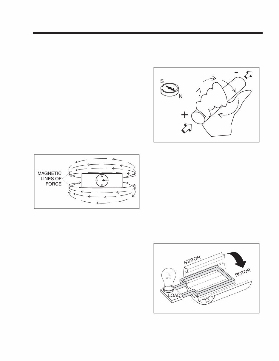
Section 1 GENERATOR FUNDAMENTALS MAGNETISM Magnetism can be used to produce electricity and electricity can be used to produce magnetism. Much about magnetism cannot be explained by our present knowledge. However, there are certain pat- terns of behavior that are known. Application of these behavior patterns has led to the development of gen- erators, motors and numerous other devices that uti- lize magnetism to produce and use electrical energy. See Figure 1-1. The space surrounding a magnet is permeated by magnetic lines of force called “flux”. These lines of force are concentrated at the magnet's north and south poles. They are directed away from the magnet at its north pole, travel in a loop and re- enter the magnet at its south pole. The lines of force form definite patterns which vary in intensity depend- ing on the strength of the magnet. The lines of force never cross one another. The area surrounding a magnet in which its lines of force are effective is called a “magnetic field”. Like poles of a magnet repel each other, while unlike poles attract each other. Figure 1-1. – Magnetic Lines of Force ELECTROMAGNETIC FIELDS All conductors through which an electric current is flowing have a magnetic field surrounding them. This field is always at right angles to the conductor. If a compass is placed near the conductor, the compass needle will move to a right angle with the conductor. The following rules apply: • The greater the current flow through the conductor, the stronger the magnetic field around the conductor. • The increase in the number of lines of force is directly proportional to the increase in current flow and the field is distributed along the full length of the conductor. • The direction of the lines of force around a conduc- tor can be determined by what is called the “right hand rule”. To apply this rule, place your right hand around the conductor with the thumb pointing in the direction of current flow. The fingers will then be pointing in the direction of the lines of force. NOTE: The “right hand rule” is based on the “cur- rent flow” theory which assumes that current flows from positive to negative. This is opposite the “electron” theory, which states that current flows from negative to positive. Figure 1-2. – The Right Hand Rule ELECTROMAGNETIC INDUCTION An electromotive force (EMF) or voltage can be pro- duced in a conductor by moving the conductor so that it cuts across the lines of force of a magnetic field. Similarly, if the magnetic lines of force are moved so that they cut across a conductor, an EMF (voltage) will be produced in the conductor. This is the basic principal of the revolving field generator. Figure 1-3, below, illustrates a simple revolving field generator. The permanent magnet (Rotor) is rotated so that its lines of magnetic force cut across a coil of wires called a Stator. A voltage is then induced into the Stator windings. If the Stator circuit is completed by connecting a load (such as a light bulb), current will flow in the circuit and the bulb will illuminate. Figure 1-3. – A Simple Revolving Field Generator Page 3
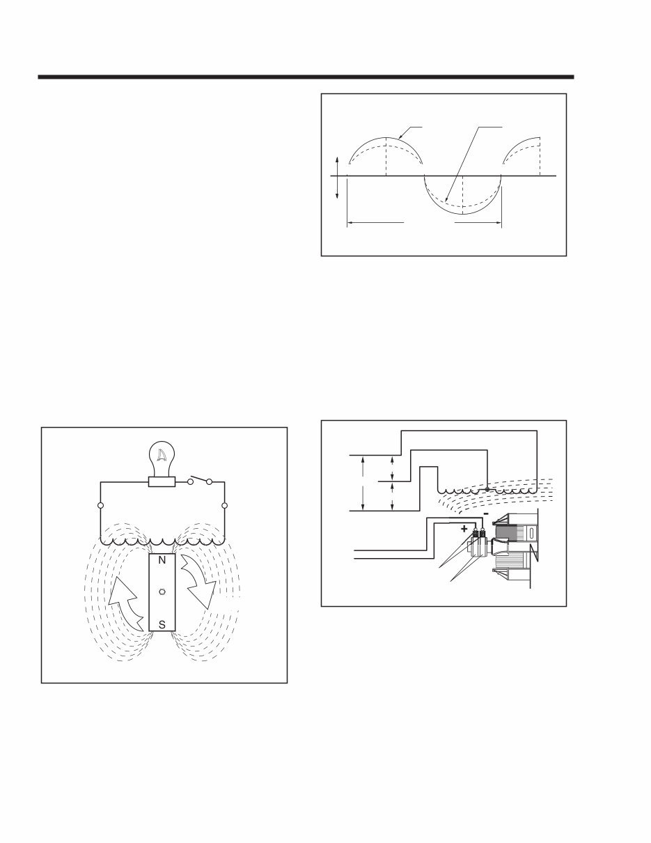
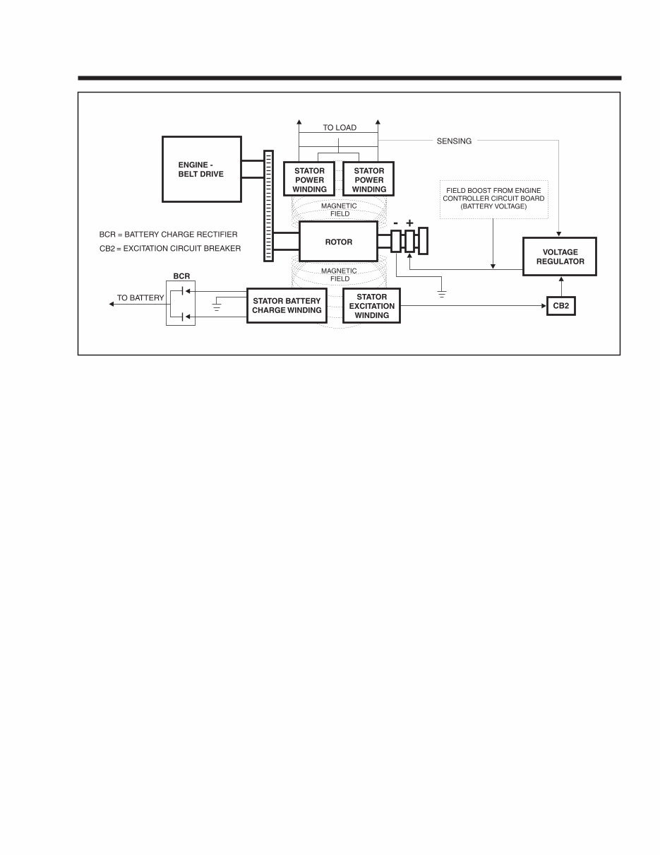
Section 1 GENERATOR FUNDAMENTALS A SIMPLE AC GENERATOR Figure 1-4 shows a very simple AC Generator. The generator consists of a rotating magnetic field called a ROTOR and a stationary coil of wire called a STA- TOR. The ROTOR is a permanent magnet which con- sists of a SOUTH magnetic pole and a NORTH mag- netic pole. As the MOTOR turns, its magnetic field cuts across the stationary STATOR. A voltage is induced into the STATOR windings. When the magnet's NORTH pole passes the STATOR, current flows in one direction. Current flows in the opposite direction when the mag- net's SOUTH pole passes the STATOR. This con- stant reversal of current flow results in an alternating current (AC) waveform that can be diagrammed as shown in Figure 1-5. The ROTOR may be a 2-pole type having a single NORTH and a single SOUTH magnetic pole. Some ROTORS are 4-pole type with two SOUTH and two NORTH magnetic poles. The following apply: 1. The 2-pole ROTOR must be turned at 3600 rpm to produce an AC frequency of 60-Hertz, or at 3000 rpm to deliver an AC fre- quency of 50-Hertz. 2. The 4-pole ROTOR must operate at 1800 rpm to deliver a 60- Hertz AC frequency or at 1500 rpm to deliver a 50-Hertz AC frequency. Figure 1-4. – A Simple AC Generator Figure 1-5. – Alternating Current Sine Wave A MORE SOPHISTICATED AC GENERATOR Figure 1-6 represents a more sophisticated genera- tor. A regulated direct current is delivered into the ROTOR windings via carbon BRUSHES AND SLIP RINGS. This results in the creation of a regulated magnetic field around the ROTOR. As a result, a reg- ulated voltage is induced into the STATOR. Regulated current delivered to the ROTOR is called “EXCITATION” current. Figure 1-6. – A More Sophisticated Generator See Figure 1-7 (next page). The revolving magnetic field (ROTOR) is driven by the engine at a constant speed. This constant speed is maintained by a mechanical engine governor. Units with a 2-pole rotor require an operating speed of 3600 rpm to deliver a 60-Hertz AC output. Engine governors are set to maintain approximately 3720 rpm when no electrical loads are connected to the generator. STATOR BRUSHES 120 V 120 V SLIP RINGS AC OUTPUT DC CURRENT STATOR 240 V CURRENT VOLTAGE ONE CYCLE 0 180 360 (+) (-) STATOR ROTOR MAGNETIC FIELD Page 4
Section 1 GENERATOR FUNDAMENTALS NOTE: AC output frequency at 3720 rpm will be about 62-Hertz. The “No-Load” is set slightly high to prevent excessive rpm, frequency and voltage droop under heavy electrical loading. Generator operation may be described briefly as fol- lows: 1. Some “residual” magnetism is normally present in the rotor and is sufficient to induce approximately 7 to 12 VAC Into the sta- tor's AC power windings. 2. During startup, an engine controller circuit board delivers bat- tery voltage to the rotor, via the brushes and slip rings. a. The battery voltage is called “Field Boost”. b. Flow of direct current through the ROTOR increases the strength of the magnetic field above that of “residual” magnetism alone. 3. “Residual” plus “Field Boost” magnetism induces a voltage into the Stator excitation (DPE), battery charge and AC Power windings. 4. Excitation winding unregulated AC output is delivered to an electronic voltage regulator, via an excitation circuit breaker. a. A “Reference” voltage has been pre-set into the Voltage Regulator. b. An “Actual” (“sensing”) voltage is delivered to the Voltage Regulator via sensing leads from the Stator AC power windings. c. The Regulator “compares” the actual (sens- ing) voltage to its pre-set reference voltage. (1) If the actual (sensing) voltage is greater than the pre-set reference voltage, the Regulator will decrease the regulated cur- rent flow to the Rotor. (2) If the actual (sensing) voltage is less than the pre-set reference voltage, the Regulator will increase the regulated cur- rent flow to the Rotor. (3) In the manner described, the Regulator maintains an actual (sensing) voltage that is equal to the pre-set reference voltage. NOTE: The Voltage Regulator also changes the Stator excitation windings alternating current (AC) output to direct current (DC). 5. When an electrical load is connected across the Stator power windings, the circuit is completed and an electrical current will flow. 6. The Rotor's magnetic field also induces a voltage Into the Stator battery charge windings. a. Battery charge winding AC output is deliv- ered to a battery charge rectifier (BCR) which changes the AC to direct current (DC). b. The rectified DC is then delivered to the unit battery, to maintain the battery in a charged state. c. A one ohm, 25 watt Resistor is installed in series with the grounded side of the battery charge circuit. Page 5 Figure 1-7. – Generator Operating Diagram
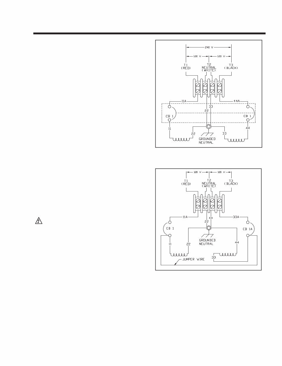
Section 1 GENERATOR FUNDAMENTALS FIELD BOOST When the engine is cranked during startup, the engine control circuit board Terminals 9, 10, and 11 (Wire 14) are energized with 12 VDC. Connected to a Wire 14 is a resistor (R2) and a diode (D2). Battery current flows through the 20 ohm 12-watt resistor and the field boost diode D2, the voltage is reduced to 3-5 VDC. After passing through R2 and D2 it becomes Wire 4 and current travels to the Rotor via brushes and slip rings. This is called “Field Boost” current. The effect is to “flash the field” every time the engine is cranked. Field boost current helps ensure that suffi- cient “pickup” voltage is available on every startup to turn the Voltage Regulator on and build AC output voltage. NOTE: Loss of the Field Boost function may or may not result in loss of AC power winding out- put. If Rotor residual magnetism alone is suffi- cient to turn the Regulator on, loss of Field Boost may go unnoticed. However, if residual magnet- ism alone is not enough to turn the Regulator on, loss of the Field Boost function will result in loss of AC power winding output to the load. The AC output voltage will then drop to a value commen- surate with the Rotor's residual magnetism (about 7-12 VAC). GENERATOR AC CONNECTION SYSTEM The generator set is equipped with dual stator AC power windings. These two stator windings supply electrical power to customer electrical loads by means of a dual two-wire connection system. Generators may be installed to provide the following outputs: 1. 120/240 VAC loads — one load with a maximum total wattage requirement equal to the generator’s rated power output, and 240 VAC across the generator output terminals; or two separate loads, each with a maximum total wattage requirement equal to half of the generator’s rated power output (in watts), and 120VAC across the generator output terminals. Figure 1.9 shows the gen- erator lead wire connections for 120/240 VAC loads. 2. 120 VAC loads only — one load with a maximum total wattage requirement equal to the generator’s rated power output (in watts), and 120V across the generator output terminals. Figure 1.8 shows the generator lead wire connections for 120VAC ONLY. The generator set can be used to supply electrical power for operating one of the following electrical loads: • QUIETPACT 75D: 120 and/or 240 VAC, single phase, 60-Hertz electrical loads. These loads can require up to 7500 watts (7.5 kW) of total power, but cannot exceed 62.5 AC amperes of current at 120 VAC or exceed 31.2 AC amperes at 240 VAC. CAUTION! Do not overload the generator. Some installations may require that electrical loads be alternated to avoid overloading. Applying excessively high electrical loads may damage the generator and may shorten its life. Add up the rated watts of all electrical lighting, appliance, tool and motor loads the generator will power at one time. This total should not be greater than the wattage capacity of the gener- ator. If an electrical device nameplate gives only volts and amps, multiply volts times amps to obtain watts (volts x amps = watts). Some electric motors require more watts of power (or amps of current) for starting than for continu- ous operation. LINE BREAKERS (120 VAC ONLY): Protects generator’s AC output circuit against overload (i.e., prevents unit from exceeding wattage/amperage capacity). The circuit breaker rat- ings are as follows: GENERATOR CONVERSION TO 120 VAC ONLY — DUAL CIRCUITS NOTE: Conversion of a QUIETPACT™ generator from "120/240 VAC dual voltage" to "120 VAC only - dual circuits" (or vice-versa) requires rerouting wires within the unit enclosure. It is rec- ommended that this conversion be performed by a Generac Authorized Service Dealer. Figure 1-9 shows the stator power winding connec- tions for 120 VAC only - dual circuits. Two stator power windings are used, with each winding capable of supplying half of the unit's rated wattage/amperage capacity. The circuit from each winding is protected against overload by a line breaker (CB1 and CB1A). Line breakers CB1 and CB1A have a trip rating of 35 amps. To convert from "120/240 VAC dual voltage" to "120 VAC only - dual circuits", disconnect battery power from the generator and reverse stator lead Wires 33 and 44 as follows: NOTE: It is necessary to feed stator lead Wires 33 and 44 through grommets on the electrical enclo- sure and engine control box in order to perform the rerouting outlined below. The front and top unit enclosure panels, as well as the user control panel, must be removed to perform this. After re- routing, wires should be properly tied down to prevent chafing or contact with moving internal components 1. Remove stator lead Wire 33, as shown in Figure 1-8, from the ground stud adjacent to the four-position terminal block. Page 6 Model Circuit Breaker 1 Circuit Breaker 2 QuietPact 75D 35A 35A
Section 1 GENERATOR FUNDAMENTALS Reroute stator lead 44 from the line side terminal of CB1 (renamed as CB1A in Figure 1-9) to the ground stud location previously occupied by stator lead Wire 33. 2. Move smaller gauge (#18 AWG) Wire labeled #44 (not shown), from the top of CB1A to the top of CB1. Renumber this Wire 11. 3. Reroute stator lead Wire 33, removed in step 1, to the line side terminal on CB1A. 4. Renumber ground Wire 33, located between the four-position terminal block and ground in Figure 1-8, as ground Wire 44, as shown in Figure 1-9. 5. Renumber Wire 44A from Figure 1-8 as Wire 33A in Figure 1-9. 6. Connect a 12 AWG jumper wire between line breakers CB1 and CB1A, as shown in Figure 1-9. 7. Remove the "tie bar" between the two-line breaker switch han- dles. When connecting vehicle load leads, the following rules apply: • Connect 120 VAC, single-phase, 60-Hertz, AC electrical loads, requiring up to the trip rating of cir- cuit breaker CB1, across AC output leads T1 (red) and T2 (white). • Connect 120 VAC, single-phase, 60-Hertz, AC electrical loads, requiring up to the trip rating of cir- cuit breaker CB1A, across AC output leads T3 (black) and T2 (white). • Try to keep the load balanced between the two cir- cuit breakers and the stator windings. • The neutral line (T2, white) on all units is a ground- ed neutral. Do NOT connect electrical loads in excess of any circuit breaker rating, or problems will develop with circuit breaker tripping, which causes a loss of AC output. Also, do NOT exceed the generator's rated wattage capacity. Add the watts or amps of all lighting, appliance, tool, and motor loads the generator will operate at one time. This total should be less than the unit's rated wattage/amperage capacity. Figure 1-8. – Connection for 120/240 VAC Dual Voltage Figure 1-9 - Connection for 120 VAC Only — Dual Circuits Page 7
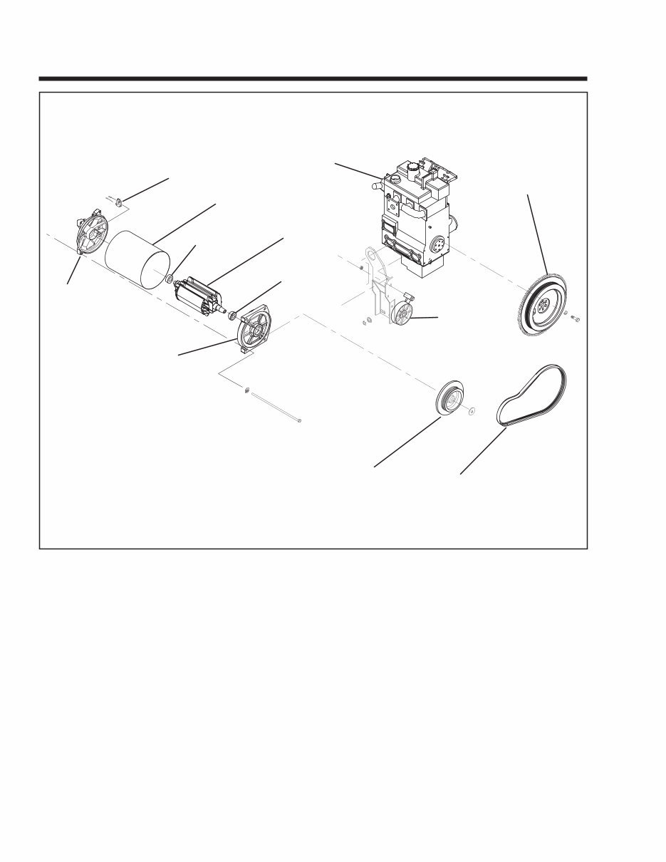
Section 2 MAJOR GENERATOR COMPONENTS ROTOR ASSEMBLY The Rotor is sometimes called the “revolving field”, since it provides the magnetic field that induces a voltage into the stationary Stator windings. Slip rings on the Rotor shaft allow excitation current from the voltage regulator to be delivered to the Rotor wind- ings. The Rotor is driven by the engine at a constant speed through a pulley and belt arrangement. The QUIETPACT 75D utilizes a 2-pole Rotor. This type of Rotor must be driven at 3600 rpm for a 60- Hertz AC output, or at 3000 rpm for a 50-Hertz output. Slip rings should be cleaned. If dull or tarnished, clean them with fine sandpaper (a 400 grit wet sand- paper is recommended). DO NOT USE ANY METAL- LIC GRIT OR ABRASIVE TO CLEAN SLIP RINGS. STATOR ASSEMBLY The Stator is assembled between the front and rear bearing carriers and retained in that position by four Stator studs. Windings included in the Stator assem- bly are (a) dual AC power windings, (b) an excitation or DPE winding, and (c) a battery charge winding. A total of eleven (11) leads are brought out of the Stator as follows: 1. Four (4) Stator power winding output leads (Wires No. 11, 22, 33 and 44). These leads deliver power to connected electrical loads. 2. Stator Power winding “sensing” leads (11 and 22). These leads deliver an “actual voltage signal to the electronic Voltage Regulator. Page 8 Figure 2-1. Exploded View of Generator BRUSH HOLDER STATOR ROTOR ENGINE FLYWHEEL/PULLEY PULLEY TENSIONER BELT BEARING BEARING CARRIER BEARING CARRIER BEARING
This is a comprehensive service repair manual for the Generac 4270, featuring high-quality diagrams and detailed instructions for servicing and repairing your Generac. Whether you are a professional mechanic or a DIY enthusiast, this manual is an essential tool for saving on service repair and maintenance costs.
Dimensions and features
4-cycle engine theory
Section 1: General
Section 2: Air cleaners and carburetion
Section 3: Mechanical governor
Section 4: Optional idle control
Section 5: Rewind starters
Section 6: Electric starters and batteries
Section 7: Covers and shrouds
Section 8: Ignition system
Section 9: Valve train
Section 10: Piston, rings, and rod
Section 11: Crankshaft and camshaft
Section 12: Lubrication
Section 13: Troubleshooting
Specifications
This service repair manual is available for instant download, eliminating shipping costs and waiting time. It is compatible with all versions of Windows & Mac, as well as various devices such as APP ISO, iPhone, iPod, and Android. The language of the manual is English, and it requires Adobe Reader for access. Take advantage of this valuable resource to enhance your understanding of your Generac and to facilitate cost-effective maintenance and repairs.