

CUMMINS PCC2100 Wiring Diagram OPERATOR Manual
What's Included?
Fast Download Speeds
Online & Offline Access
Access PDF Contents & Bookmarks
Full Search Facility
Print one or all pages of your manual
PowerCommand
Control
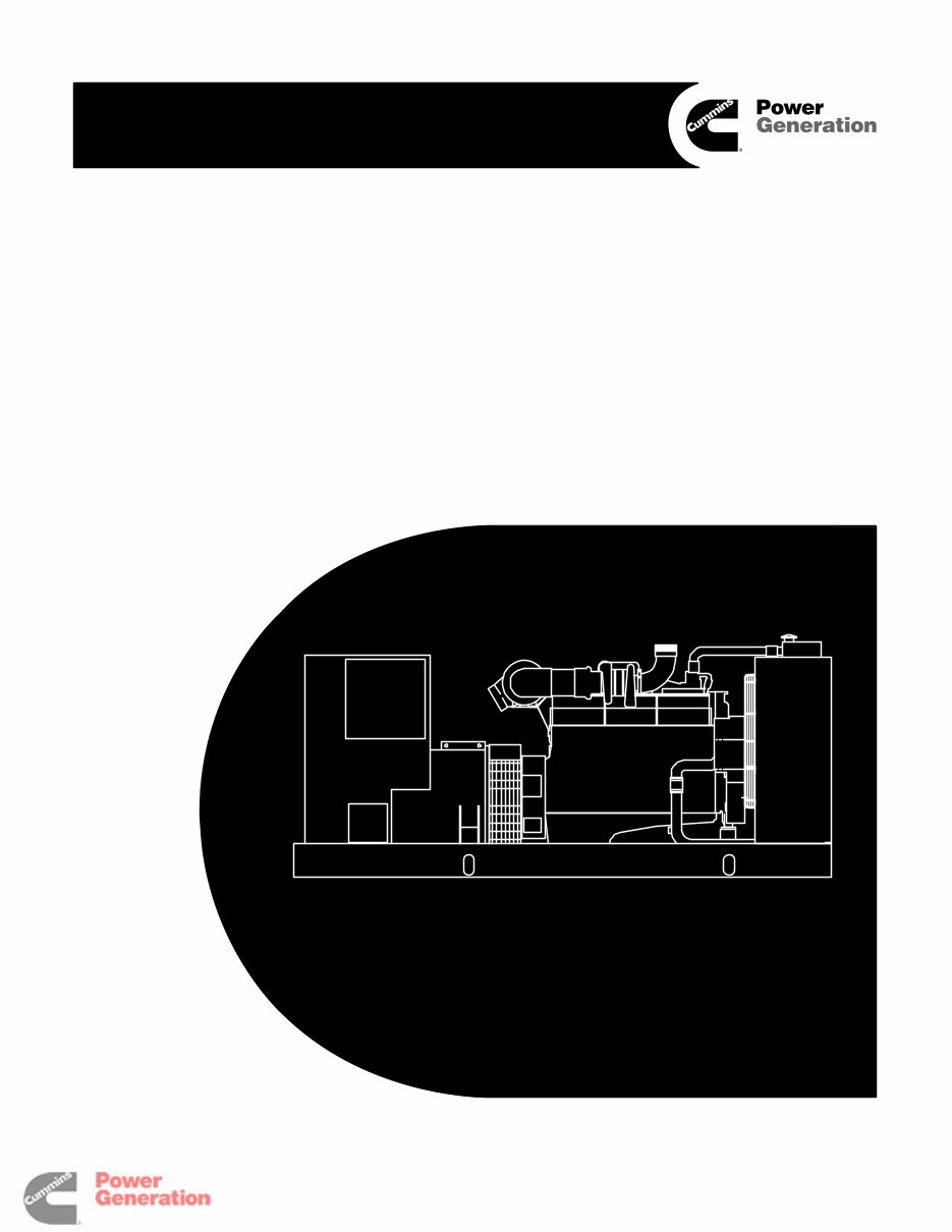
2100 Series
Generator Sets
Printed in U.S.A.
960-0176C 02-2004
Operator’s Manual
Models
DFBF, DFCB, DFCC, DFCE
Redistribution or publication of this document
by any means, is strictly prohibited.

i
Table of Contents
SECTION TITLE PAGE
IMPORTANT SAFETY INSTRUCTIONS iii . . . . . . . . . . . . . . . . . . . . . . . . . . . . . . .
1 INTRODUCTION
General 1-1 . . . . . . . . . . . . . . . . . . . . . . . . . . . . . . . . . . . . . . . . . . . . . . . . . . . . . . . .
How to Obtain Service 1-1 . . . . . . . . . . . . . . . . . . . . . . . . . . . . . . . . . . . . . . . . . . .
2 SPECIFICATIONS 2-1 . . . . . . . . . . . . . . . . . . . . . . . . . . . . . . . . . . . . . . . . . . . . . . . . .
3 CONTROL OPERATION
General 3-1 . . . . . . . . . . . . . . . . . . . . . . . . . . . . . . . . . . . . . . . . . . . . . . . . . . . . . . . .
Prestart Checks 3-1 . . . . . . . . . . . . . . . . . . . . . . . . . . . . . . . . . . . . . . . . . . . . . . . . .
Control Panel Power On/Off Modes 3-2 . . . . . . . . . . . . . . . . . . . . . . . . . . . . . . . .
Front Panel 3-4 . . . . . . . . . . . . . . . . . . . . . . . . . . . . . . . . . . . . . . . . . . . . . . . . . . . . .
Starting 3-6 . . . . . . . . . . . . . . . . . . . . . . . . . . . . . . . . . . . . . . . . . . . . . . . . . . . . . . . .
Stopping 3-7 . . . . . . . . . . . . . . . . . . . . . . . . . . . . . . . . . . . . . . . . . . . . . . . . . . . . . . .
Menu Display and Buttons 3-11 . . . . . . . . . . . . . . . . . . . . . . . . . . . . . . . . . . . . . . .
Main Menus 3-13 . . . . . . . . . . . . . . . . . . . . . . . . . . . . . . . . . . . . . . . . . . . . . . . . . . .
Adjusting Default Settings 3-15 . . . . . . . . . . . . . . . . . . . . . . . . . . . . . . . . . . . . . . .
System Messages 3-15 . . . . . . . . . . . . . . . . . . . . . . . . . . . . . . . . . . . . . . . . . . . . . .
Controller Configuration Menu 3-16 . . . . . . . . . . . . . . . . . . . . . . . . . . . . . . . . . . . .
Engine Menu 3-18 . . . . . . . . . . . . . . . . . . . . . . . . . . . . . . . . . . . . . . . . . . . . . . . . . . .
Alternator Menu 3-20 . . . . . . . . . . . . . . . . . . . . . . . . . . . . . . . . . . . . . . . . . . . . . . . .
Adjust Menu 3-22 . . . . . . . . . . . . . . . . . . . . . . . . . . . . . . . . . . . . . . . . . . . . . . . . . . .
Faults Menu 3-24 . . . . . . . . . . . . . . . . . . . . . . . . . . . . . . . . . . . . . . . . . . . . . . . . . . .
System Menu 3-26 . . . . . . . . . . . . . . . . . . . . . . . . . . . . . . . . . . . . . . . . . . . . . . . . . .
History Menu 3-28 . . . . . . . . . . . . . . . . . . . . . . . . . . . . . . . . . . . . . . . . . . . . . . . . . . .
About Menu 3-30 . . . . . . . . . . . . . . . . . . . . . . . . . . . . . . . . . . . . . . . . . . . . . . . . . . . .
Power Transfer Menu 3-32 . . . . . . . . . . . . . . . . . . . . . . . . . . . . . . . . . . . . . . . . . . .
-
California
Proposition 65 Warning
Diesel engine exhaust and some of its constituents are known
to the State of California to cause cancer, birth defects, and
other reproductive harm.
Redistribution or publication of this document
by any means, is strictly prohibited.

ii
SECTION TITLE PAGE
4 TROUBLESHOOTING
General 4-1 . . . . . . . . . . . . . . . . . . . . . . . . . . . . . . . . . . . . . . . . . . . . . . . . . . . . . . . .
Safety Considerations 4-1 . . . . . . . . . . . . . . . . . . . . . . . . . . . . . . . . . . . . . . . . . . . .
Status Indicators 4-2 . . . . . . . . . . . . . . . . . . . . . . . . . . . . . . . . . . . . . . . . . . . . . . . .
Line Circuit Breaker (Optional) 4-2 . . . . . . . . . . . . . . . . . . . . . . . . . . . . . . . . . . . .
Control and Diagnostics VIA Network or PC (Laptop) 4-2 . . . . . . . . . . . . . . . . .
Fault Codes 4-4 . . . . . . . . . . . . . . . . . . . . . . . . . . . . . . . . . . . . . . . . . . . . . . . . . . . . .
Fault Code Table 4-4 . . . . . . . . . . . . . . . . . . . . . . . . . . . . . . . . . . . . . . . . . . . . . . . .
Troubleshooting Table 4-7 . . . . . . . . . . . . . . . . . . . . . . . . . . . . . . . . . . . . . . . . . . . .
5 MAINTENANCE
General 5-1 . . . . . . . . . . . . . . . . . . . . . . . . . . . . . . . . . . . . . . . . . . . . . . . . . . . . . . . .
Maintenance Schedule 5-2 . . . . . . . . . . . . . . . . . . . . . . . . . . . . . . . . . . . . . . . . . . .
Generator Set Inspection 5-3 . . . . . . . . . . . . . . . . . . . . . . . . . . . . . . . . . . . . . . . . .
Generator Set Maintenance (Battery Disconnected) 5-4 . . . . . . . . . . . . . . . . . .
Lubrication System 5-5 . . . . . . . . . . . . . . . . . . . . . . . . . . . . . . . . . . . . . . . . . . . . . .
Crankcase Breather 5-7 . . . . . . . . . . . . . . . . . . . . . . . . . . . . . . . . . . . . . . . . . . . . . .
Cooling System 5-8 . . . . . . . . . . . . . . . . . . . . . . . . . . . . . . . . . . . . . . . . . . . . . . . . .
Change Air Piping 5-8 . . . . . . . . . . . . . . . . . . . . . . . . . . . . . . . . . . . . . . . . . . . . . . .
Fuel System 5-8 . . . . . . . . . . . . . . . . . . . . . . . . . . . . . . . . . . . . . . . . . . . . . . . . . . . .
Air Cleaner 5-9 . . . . . . . . . . . . . . . . . . . . . . . . . . . . . . . . . . . . . . . . . . . . . . . . . . . . .
Batteries 5-10 . . . . . . . . . . . . . . . . . . . . . . . . . . . . . . . . . . . . . . . . . . . . . . . . . . . . . .
6 OPERATING RECOMMENDATIONS
No-Load Operation 6-1 . . . . . . . . . . . . . . . . . . . . . . . . . . . . . . . . . . . . . . . . . . . . . .
Exercise Period 6-1 . . . . . . . . . . . . . . . . . . . . . . . . . . . . . . . . . . . . . . . . . . . . . . . . .
Low Operating Temperature 6-1 . . . . . . . . . . . . . . . . . . . . . . . . . . . . . . . . . . . . . .
High Operating Temperature 6-1 . . . . . . . . . . . . . . . . . . . . . . . . . . . . . . . . . . . . . .
7 OPTIONAL ENCLOSURE FEATURES
General 7-1 . . . . . . . . . . . . . . . . . . . . . . . . . . . . . . . . . . . . . . . . . . . . . . . . . . . . . . . .
External Receptacle 7-1 . . . . . . . . . . . . . . . . . . . . . . . . . . . . . . . . . . . . . . . . . . . . .
Overfill Alarm 7-2 . . . . . . . . . . . . . . . . . . . . . . . . . . . . . . . . . . . . . . . . . . . . . . . . . . .
External Emergency Stop Switch 7-2 . . . . . . . . . . . . . . . . . . . . . . . . . . . . . . . . . .
AC Distribution Panel 7-3 . . . . . . . . . . . . . . . . . . . . . . . . . . . . . . . . . . . . . . . . . . . .
Fuel Transfer Pump 7-4 . . . . . . . . . . . . . . . . . . . . . . . . . . . . . . . . . . . . . . . . . . . . . .
External Alarm Panel 7-6 . . . . . . . . . . . . . . . . . . . . . . . . . . . . . . . . . . . . . . . . . . . . .
External Fuel Fill Box 7-7 . . . . . . . . . . . . . . . . . . . . . . . . . . . . . . . . . . . . . . . . . . . .
Redistribution or publication of this document
by any means, is strictly prohibited.

1-1
1. Introduction
GENERAL
Each operator should read this manual before oper-
ating the set for the first time. A generator set (gen-
set) must be operated and maintained properly if
you are to expect safe and reliable operation. The
manual includes a troubleshooting guide and a
maintenance schedule.
The engine manual is included with the set. Where
there is conflicting information, this manual takes
precedence over the engine manual.
WARNING
Improper operation and mainte-
nance can lead to severe personal injury or loss
of life and property by fire, electrocution, me-
chanical breakdown or exhaust gas asphyxi-
ation. Read and follow the safety precautions
on page iii and carefully observe all instructions
and precautions in this manual.
HOW TO OBTAIN SERVICE
When the generator set requires servicing, contact
your nearest Cummins Power Generation distribu-
tor. Factory-trained Parts and Service representa-
tives are ready to handle all your service needs.
To contact your local Cummins Power Generation
distributor in the United States or Canada, call
1-800-888-6626 (this automated service utilizes
touch-tone phones only). By selecting Option 1
(press 1), you will be automatically connected to the
distributor nearest you.
If you are unable to contact a distributor using the
automated service, consult the Yellow Pages. Typi-
cally, our distributors are listed under:
GENERATORS-ELECTRIC or
ELECTRICAL PRODUCTS
For outside North America, call Cummins Power
Generation, 1-763-574-5000, 7:30 AM to 4:00 PM,
Central Standard Time, Monday through Friday. Or,
send a fax to Cummins Power Generation using the
fax number 1-763-528-7229.
When contacting your distributor, always supply the
complete Model, Specification, and Serial Number
as shown on the generator set nameplate.
WARNING
INCORRECT SERVICE OR PARTS REPLACEMENT CAN RESULT IN SEVERE PERSONAL IN-
JURY, DEATH, AND/OR EQUIPMENT DAMAGE. SERVICE PERSONNEL MUST BE TRAINED
AND EXPERIENCED TO PERFORM ELECTRICAL AND/OR MECHANICAL SERVICE.
Copyright 2003 Cummins Power Generation. All rights reserved.
Cummins and PowerCommand are registered trademarks of Cummins Inc.
Redistribution or publication of this document
by any means, is strictly prohibited.

1-2
THIS PAGE LEFT INTENTIONALLY BLANK
Redistribution or publication of this document
by any means, is strictly prohibited.
2-1
2. Specifications
MODEL DFBF DFCB DFCC DFCE
Engine
Cummins Diesel Series NT855 NTA855 NTA855 NTA855
Generator kW Rating See Genset Nameplate for rating information.
Electrical System
Starting Voltage
Battery
Group Number
CCA (minimum)
Cold Soak @ 0° F (-18° C)
24 Volts DC
Two, 12 Volt
8D
1400
Cooling System
Capacity with Standard Radiator 13.5 Gal (51 L) 15 Gal (57 L)
Lubricating System
Oil Capacity with Filters
Oil Type*
10.5 Gal (40 L) 10 Gal (38 L)
* Refer to Cummins engine Operation and Maintenance Manual for lubricating oil recommendations/specifications.
FUEL CONSUMPTION (STANDBY/FULL LOAD/60HZ)
MODEL DFBF DFCB DFCC DFCE
US gph (L/hr) 20.4 (77.3) 22.5 (85.3) 24.4 (92.5) 29.1 (110.3)
OIL PRESSURE WARNING AND
SHUTDOWN LIMITS
Normal Oil Pressure
Warning Limit
Shutdown Limit
35-50 psi (242-345 kPa)
30 psi (207 kPa)
25 psi (172 kPa)
Idle Oil Pressure
Warning Limit
Shutdown Limit
15 psi (104 kPa)
12 psi (83 kPa)
8 psi (55 kPa)
Redistribution or publication of this document
by any means, is strictly prohibited.

2-2
THIS PAGE LEFT INTENTIONALLY BLANK
Redistribution or publication of this document
by any means, is strictly prohibited.
3-1
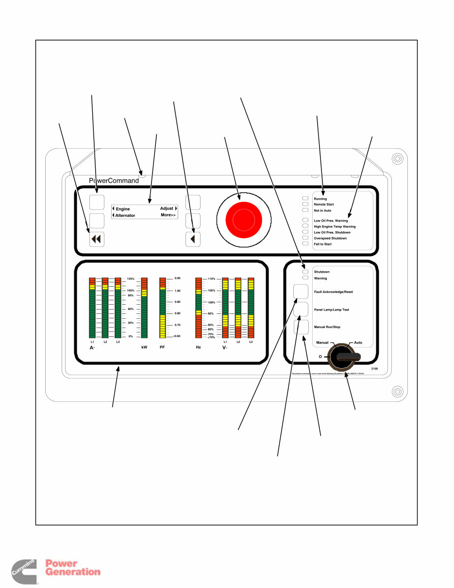
3. Control Operation
GENERAL
The following describes the function and operation
of the PowerCommand
2100 Control (PCC). All in-
dicators, control switches/buttons and digital dis-
play are located on the face of the control panel as
illustrated in Figure 3-1.
This section covers prestart checks, starting and
stopping and operating the generator set. Each op-
erator should read through this entire section before
attempting to start the set. It is essential that the op-
erator be completely familiar with the set and the
PCC control. Refer to Section 6 for operating rec-
ommendations.
Before starting, be sure the following checks have
been made and the unit is ready for operation.
PRESTART CHECKS
Lubrication
Check the engine oil level. Keep the oil level near as
possible to the dipstick high mark without overfilling.
Coolant
Check the engine coolant level. Refer to “Cooling
Systems” in the Maintenance section of this manu-
als for proper procedure.
Fuel
Make sure the fuel tanks have sufficient fuel and
that fuel system is primed. Check to make sure
there are no leaks and that all fittings are tight.
Ventilation
Make sure the generator set cooling inlet/outlet and
exhaust ventilation openings are clear (not blocked)
and operational.
Remove all loose debris from surrounding area of
generator set. Air flow from the radiator fan can
blow loose items around and into ventilation open-
ings.
Exhaust
Check to make sure entire exhaust system is tight,
that no combustible materials are near system, and
gases are discharged away from building openings.
Redistribution or publication of this document
by any means, is strictly prohibited.

3-2
CONTROL PANEL POWER ON/OFF
MODES
The power on/off modes of the control panel and op-
erating software are Power On, Screen Saver and
Sleep/Awake.
Power On Mode: In this mode, power is continu-
ously supplied to the control panel. The control’s
operating software and control panel LEDs/digital
display will remain active until the Screen Saver
mode is activated.
Screen Saver Mode: Power to the digital display is
removed after 30 minutes (generator set not run-
ning or running). The 30 minute timer resets and be-
gins after each control panel action (any button or
switch selection) or signal received by the operating
software. All LEDs on the control panel operate nor-
mally during Screen Saver mode, indicating that the
operating software is active (Awake mode).
When a “Warning” signal is sensed by the PCC (for
example, low coolant temp), the control displays the
warning message.
Sleep/Awake Mode: In the Sleep mode, the con-
trol’s operating software is inactive and the LEDs
and the digital display on the control panel are all off.
Sleep mode is a feature used to reduce battery
power consumption when the control is not being
used and the O/Manual/Auto switch is in the O posi-
tion.
When all conditions are met (i.e., no unacknowl-
edged faults and O/Manual/Auto switch is in the O
position) the Sleep mode is activated.
The operating software is initialized and the digital
display and control panel LEDs are turned on in re-
sponse to moving/pressing the following control
panel switch/buttons:
• Off/Manual/Auto switch
• Emergency Stop button
• Fault Acknowledge/Reset button
• Panel Lamp/Lamp Test button
To activate the control and view the menu display
without starting the generator set, press Fault Ac-
knowledge or Panel Lamp button or move mode
switch from O to Manual.
The InPower service tool is required to enable or
disable the Sleep mode. When shipped from the
factory, Sleep mode is disabled. When disabled, the
operating software will always remain active
(Awake mode). If network and/or power transfer
control (PTC) feature is installed, the sleep mode is
not available.
The InPower service tool is required to select the de-
sired mode. Contact an authorized service center for
assistance.
Redistribution or publication of this document
by any means, is strictly prohibited.
3-3
PANEL
LAMP
(1 of 3)
CONFIGURABLE
INDICATORS
MANUAL
RUN/STOP
BUTTON
OFF/MANUAL/
AUTO SWITCH
SHUTDOWN
AND WARNING
STATUS
INDICATORS
EMERGENCY
STOP PUSH
BUTTON
(Pull to reset)
HOME
BUTTON
ANALOG AC
METERING
PANEL
(OPTIONAL)
DIGITAL
DISPLAY
MENU
SELECTION
BUTTON
(1 of 4)
PREVIOUS
MAIN MENU
BUTTON
FAULT
ACKNOWLEDGEMENT/
RESET BUTTON
RUNNING/REMOTE
START/NOT IN AUTO
INDICATORS
PANEL LAMP
AND LAMP
TEST
BUTTON
FIGURE 3-1. FRONT PANEL
Redistribution or publication of this document
by any means, is strictly prohibited.
You're Reading a Preview
What's Included?
Fast Download Speeds
Online & Offline Access
Access PDF Contents & Bookmarks
Full Search Facility
Print one or all pages of your manual
$41.99
$54.99
Viewed 69 Times Today


Secure transaction
What's Included?
Fast Download Speeds
Online & Offline Access
Access PDF Contents & Bookmarks
Full Search Facility
Print one or all pages of your manual
$41.99
$54.99
- The Cummins PCC2100 Wiring Diagram Operator Manual - DFEG DFEH DFEJ DFEK Genset with PCC2100 PowerCommand is a valuable resource for operators, users, and owners alike.
- It includes detailed instructions and guidelines for installation, covering the DFEG, DFEH, DFEJ, and DFEK models, providing step-by-step procedures for a smooth and efficient installation process.
- The maintenance manual specifically focuses on the PCC2100 PowerCommand system, offering comprehensive guidance on proper maintenance and service.
- Detailed wiring diagrams are included for easy reference, allowing users to understand the electrical connections and configurations of the system.
- Supplementary materials such as C619 door replacement instructions and a face plate label are also included, providing further assistance in maintaining and customizing the PCC2100 system.
- The manual features an introduction to the PCC2100 system, offering insights into its features, benefits, and functionalities.
- A PCC2100 sales presentation is included, providing valuable information for potential buyers and showcasing the advantages of this cutting-edge technology.
- Specific instructions tailored to the non-can version of the PCC2100 are provided, ensuring seamless operation and compatibility.
- Overall, this manual is a comprehensive and indispensable resource for anyone involved in the operation, installation, and maintenance of this advanced genset system.


