Onan NHC, NHCV, NH Series Service Manual Cummins Onan Generator Repair Book 940-0751
What's Included?
Lifetime Access
Fast Download Speeds
Online & Offline Access
Access PDF Contents & Bookmarks
Full Search Facility
Print one or all pages of your manual
Service Manual Engine 940-0751 NHC,NHCV Spec E NH (RV) Spec J-P 4-87 Printedin USA
Safety Precautions It is recommended that you read your engine manual and be- come thoroughly acquainted with your equipment before you start the engine. LBWAR”GIThis symbol is used throughouf this manual to warn of possible serious personal injuiy. 1 - 1 This sjmbol refers to possible equip- ment damage. Fuels, electricalequipment, batteries,exhaustgases and mov- ing parts present potential hazards that could result in serious, personal injury. Take care in following these recommended pro- cedures. Safety Codes 0 All local, state and federal codes should be consulted and 0 This engine is not designed or intended for use in aircraft. complied with. Any such use is at the owner’s sole risk General 0 Provide appropriate fire extinguishers and install them in convenient locations. Use an extinguisher rated ABC by NFPA. 0 Make surethat all fastenerson the engine are secure and accurately torqued. Keep guards in position over fans, driving belts, etc. 0 If it is necessaryto make adjustmentswhile the engine is running, use extreme caution when dose to hot exhausts, moving parts, etc. Protect Against Moving Parts 0 Do not wear loose clothing in the vicinity of moving parts, such as PTO shafts, flywheels, blowers, couplings, fans, belts, etc. 0 Keep your hands away from moving parts. Batteries 0 Before starting work on the engine, disconnectbatteries to prevent inadvertent starting of the engine. 0 DO NOTSMOKEwhileservicing batteries.Lead acid bat- teries give off a highly explosive hydrogen gas which can be ignited by flame, electrical arcing or by smoking. 0 Verify battery polarity before connecting battery cables. Connect negative cable last. Fuel System 0 DO NOT fill fuel tanks while engine is running. 0 DO NOT smoke or use an open flame in the vicinity of the engine or fuel tank. Internal combustion engine fuels are highly flammable. 0 Fuel lines must be of steel piping, adequately secured, and free from leaks. Piping at the engine should be ap- proved flexible line. Do not use copper piping for flexible lines as copper will work harden and become brittle enough to break. L. , 0 Be sure all fuel supplies have a positive shutoff valve, Exhaust System 0 Exhaust products of any internal combustion engine are toxic and can cause injury, or death if inhaled. All engine applications, especially those within a confined area, should be equipped with an exhaust system to discharge gases to the outside atmosphere. 0 DO NOT use exhaust gases to heat a compartment. 0 Make sure that your exhaust system is free of leaks. En- sure that exhaust manifolds are secure and are not warped by bolts unevenly torqued. Exhaust Gas Is Deadly! Exhaust gases contain carbon monoxide, a poisonous gas that might cause unconsciousness and death. It is an odorlessand colorless gas formedduring combustion of hydrocarbon fuels. Symptoms of carbon monoxide poisoning are: 0 Dizziness 0 Vomiting 0 Headache 0 Muscular Twitching 0 Weakness and Sleepiness If you experienceany of these symptoms, get out into fresh air immediately, shut down the unit and do not use until it has been inspected. The best protection against carbon monoxide inhalation is proper installation and regular,frequent inspectionsof the com- plete exhaustsystem. If you notice achangeinthe sound orap- pearance of exhaust system, shut the unit down immediately and have it inspected and repaired at once by a competent me- chanic. Cooling System Throbbing in Temples 0 Coolants under pressure have a higher boiling point than water. DO NOT open a radiator pressure cap when cool- ant temperature is above 212 degrees F (1 00 degrees C) or while engine is running. Keep The Unit And Surrounding Area Clean 0 Make surethat oily rags are not left on or near the engine. 0 Remove all unnecessary grease and oil from the unit. Ac- cumulated grease and oil can cause overheating and subsequent engine damage and present a potential fire hazard. b 5
Table of Contents TITLE PAGE General Information .................................................... 2 Specifications ......................................................... 3 Dimensions and Clearances ............................................ 4 Assembly Torques and Special Tools .................................... 6 Engine Troubleshooting ................................................ 7 NHC. NHCV Installation Guidelines ..................................... 8 Oil System ........................................................... 12 Fuel System .......................................................... 15 Ignition and Battery Charging ......................................... 28 Starting System ....................................................... 34 Engine Disassembly ................................................... 39 Engine Wiring Diagram ................................................ 59 1
General Information c I NTR 0 D U CTI 0 N This manual dealswith specific mechanicaland elec- trical information needed by engine mechanics for troubleshooting, servicing, repairing, or overhauling the engine. Use the table of contents for a quick referenceto the separate engine system sections. Use the separate Parts Catalogs for parts identifica- tion and for establishing their proper location on assemblies. The troubleshooting guide is provided as a quick reference for locating and correcting engine trouble. The illustrations and procedures presented in each section apply to the engines listed on the cover. The flywheel-blower end of the engine is the front end so right and left sides are determined by viewing the engine from the front. The disassembly section contains major overhaul procedures for step by step removal, disassembly, inspection, repair and assembly of the engine components. If a major repair or an overhaul is necessary, a compe- tent mechanic should either do the job or supervise and check the work of the mechanic assigned to do the job to ensure that all dimensions, clearancesand torque values are within the specified tolerances. The wiring diagram on the last page of the manual shows how the electrical components are inter- connected. A parts catalog (available at the dealer level) contains detailed exploded views of each assembly and the individual piece part numbersand their proper names for ordering replacement parts. Use only Genuine Onan replacement parts to ensure quality and the best possible repair and overhaul results. When ordering parts, always use the com- plete Model and Spec number as well as the Serial number shown on the nameplate. ENGINE MODEL REFERENCE Identify your model by referring to the MODEL and SPEC (specification) NO. as shown on the unit nameplate. Always use this number and the engine serial numberwhenmaking referencetoyourengine. How to interpret MOD€L and SPEC NO. "if' $ill f 1 2 3 4 1. Factory code for general identification purposes. 2. Specific Type: # S-MANUAL starting MS--ELECTRIC starting if any. factory production modifications. 3. Factory code for designated optional equipment, 4. Specification (spec letter) which advances with 1 AWARNING j INCORRECT SERVICE OR REPLACMENT OF PARTS CAN RESULT IN SEVERE PERSONAL INJURY AND/OR EQUIPMENT DAMAGE. SERWCE PERSONNEL MUST BE QUALIFIED TO PERFORM ELECTRICAL AND/OR MECHANICAL SERVICE. . 2
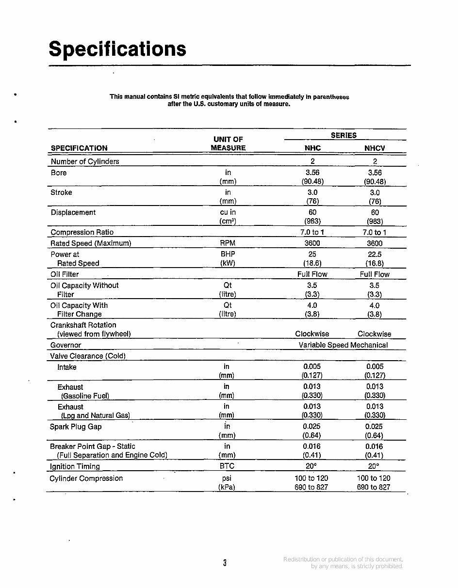
Specifications . This manual contains SI metric equivalents that follow immediately in parentheses after the U.S. customary units of measure. ~ SERIES UNIT OF SPECIFICATION MEASURE NHC NHCV Number of Cylinders 2 2 Bore in 3.56 3.56 Stroke in 3.0 3.0 Displacement cu in 60 60 Compression Ratio 7.0 to 1 7.0 to 1 Rated Speed (Maximum) RPM 3600 3600 Power at BHP 25 22.5 Rated Speed (kW) (18.6) (16.8) Oil Filter Full Flow Full Flow (mm) (90.48) (90.48) (mm) (76) (76) (cm3) (983) (983) Oil Capacity Without Qt 3.5 3.5 Filter (litre) (3.3) (3.3) Filter Change (Iitre) (3.8) (3.8) (viewed from flywheel) Clockwise Clockwise Oil Capacity With Qt 4.0 4.0 Crankshaft Rotation Governor Variable Speed Mechanical Valve Clearance (Cold) Intake in 0.005 0.005 (mm) (0.127) (0.1 27) Exhaust in 0.013 0.01 3 (Gasoline Fuel) (mm) (0.330) (0.330) Exhaust in 0.013 0.01 3 (Lpg and Natural Gas) (mm) (0.330) (0.330) Spark Plug Gap in 0.025 0.025 (mm) (0.64) (0.64) Breaker Point Gap - Static in 0.016 0.01 6 (Full Separation and Engine Cold) (mm) (0.41) (0.41) Ignition Timing BTC 20° 20° Cylinder Compression psi 100 to 120 100 to 120 690 to 827 (kP4 690 to 827 3
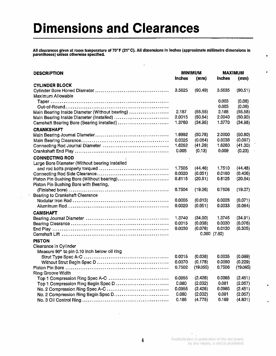
Dimensions and Clearances All clearances given at room temperature of 7OoF (21OC) . All dimensions in inches (approximate millimetre dimensions in parentheses)unless otherwise specified . DESCRIPTION CYLINDER BLOCK Cylinder Bore Honed Diameter ....................................... Maximum Allowable Taper ............................................................... Out-of-Round ....................................................... Main Bearing Inside Diameter (Without bearing) ..................... Main Bearing Inside Diameter (Installed) .............................. Camshaft Bearing Bore (Bearing installed) ........................... CRANKSHAFT Main Bearing Journal Diameter ....................................... Main Bearing Clearance .......................................... Connecting Rod Journal Diameter ................................... Crankshaft End Play .................................................. CONNECTING ROD Large Bore Diameter (Without bearing installed and rod bolts properly torqued ..................................... Connecting Rod Side Clearance ...................................... Piston Pin Bushing Bore (Without bearing) ........................... Piston Pin Bushing Bore with Bearing. (Finished bore) ..................................................... Bearing to Crankshaft Clearance Nodular iron Rod ................................................... Aluminum Rod ...................................................... CAMSHAFT Bearing Journal Diameter ............................................ Bearing Clearance .................................................... End Play .............................................................. Camshaft Lift ......................................................... PISTON Clearance in Cylinder Measure 90° to pin 0.10 inch below oil ring Strut Type Spec A-C ............................................. Without Strut Begin Spec D ...................................... Piston Pin Bore ....................................................... Ring Groove Width Top 1 Compression Ring Spec A-C ................................ Top 1 Compression Ring Begin Spec D ............................ No . 2 Compression Ring Spec A-C ................................. No . 3 Oil Control Ring .............................................. No . 2 Compression Ring Begin Spec D ............................. MINIMUM Inches (mm) 3.5625 (90.49) 2.187 (55.55) 2.001 5 (50.84) 1.3760 (34.95) 1.9992 (50.78) 0.0025 (0.064) 1.6252 (41.28) 0.005 (0.13) MAXIMUM Inches (mm) 3.5635 (90.51) 0.003 (0.08) 0.003 (0.08) 2.188 (55.58) 2.0040 (50.90) 1.3770 (34.98) 2.0000 (50.80) 0.0038 (0.097) 1.6260 (41.30) ' 0.009 (0.23) 1.7505 (44.46) 1.751 0 (44.48) 0.0020 (0.051) 0.0160 (0.406) 0.8115 (20.61) 0.8125 (20.64) 0.7504 (1 9.06) 0.7508 (1 9.07) 0.0005 (0.013) 0.0028 (0.071) 0.0020 (0.051) 0.0033 (0.084) 1.3740 (34.90) 1.3745 (34.91) 0.0015 (0.038) 0.0030 (0.076) 0.0030 (0.076) 0.0120 (0.305) 0.300 (7.62) 0.001 5 (0.038) 0.0035 (0.089) 0.0070 (0.178) 0.0090 (0.229) 0.7502 (19.055) 0.7506 (19.065) 0.0955 (2.426) 0.0965 (2.451) 0.080 (2.032) 0.081 (2.057) 0.0955 (2.426) 0.0965 (2.451) 0.080 (2.032) 0.081 (2.057) 0.188 (4.775) 0.189 (4.801) 4
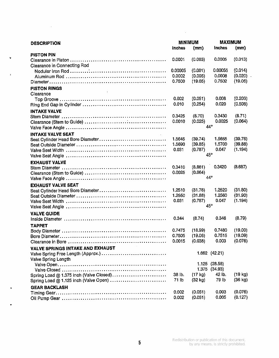
DESCRIPTION MINIMUM MAXIMUM Inches (mm) Inches (mm) Y . PISTON PIN Clearance in Piston .............................................. Clearance in Connecting Rod Nodular Iron Rod .............................................. Aluminum Rod ................................................ Diameter ........................................................ PISTON RINGS Clearance Top Groove ................................................... Ring End Gap in Cylinder ........................................ INTAKE VALVE Stem Diameter .................................................. Clearance (Stem to Guide) ....................................... Valve Face Angle ................................................ INTAKE VALVE SEAT Seat Cylinder Head Bore Diameter ................................ Seat Outside Diameter ........................................... Valve Seat Width ................................................ Valve Seat Angle ................................................ EXHAUST VALVE Stem Diameter .................................................. Clearance (Stem to Guide) ....................................... Valve Face Angle ................................................ EXHAUST VALVE SEAT Seat Cylinder Head Bore Diameter ................................ Seat Outside Diameter ........................................... Valve Seat Width ................................................ Valve Seat Angle ................................................ VALVE GUIDE Inside Diameter ................................................. TAPPET Body Diameter .................................................. Bore Diameter ................................................... Clearance in Bore ............................................... VALVE SPRINGS INTAKE AND EXHAUST Valve Spring Length Valve Spring Free Length (Approx.) ............................... Valve Open .................................................... Spring Load @ 1.375 inch (Valve Closed) .......................... Spring Load @ 1.125 inch (Valve Open) ........................... Timing Gear. .................................................... Oil Pump Gear .................................................. Valve Closed .................................................. GEAR BACKLASH 0.0001 (0.003) 0.0005 (0.013) 0.00005 (0.001) 0.00055 (0.014) 0.0002 (0.005) 0.0008 (0.020) . 0.7500 (19.05) 0.7502 (19.06) 0.002 (0.051) 0.008 (0.203) 0.010 (0.254) 0.020 (0.508) 0.3425 (8.70) 0.3430 (8.71) 0.0010 (0.025) 0.0025 (0.064) 44" 1.5645 (39.74) 1.5655 (39.76) 1.5690 (39.85) 1.5700 (39.88) 0.031 (0.787) 0.047 (1.194) 45" 0.341 0 (8.661 ) 0.3420 (8.687) 0.0025 (0.064) 440 1.251 0 (31.78) 1.2520 (31.80) 1.2550 (31.88) 1.2560 (31.90) 0.031 (0.787) 0.047 (1.194) 45O 0.344 (8.74) 0.346 (8.79) 0.7475 (1 8.99) 0.7480 (1 9.00) 0.7505 (19.06) 0.7515 (19.09) 0.0015 (0.038) 0.003 (0.076) 1.662 (42.21) I . 125 (28.58) 1:375 (34.93) 38Ib . (17 kg) 42Ib . (19 kg) 71 Ib (32 kg) 79 Ib (36 kg) 0.002 (0.051) 0.003 (0.076) 0.002 (0.051) 0.005 (0.127) 5
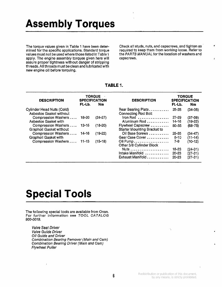
Assembly Torques The torque values given in Table 1 have been deter- mined for the specific applications. Standard torque values must not be used where those listed in Table 1 apply. The engine assembly torques given here will assure proper tightness without danger of stripping threads. All threads must beclean and lubricatedwith new engine oil before torquing. Check all studs, nuts, and capscrews, and tighten as required to keep them from working loose. Refer to the PARTS MANUAL for the location of washers and capscrews. Y TABLE 1. DESCRIPTION Cylinder Head Nuts (Cold) Asbestos Gasket without Asbestos Gasket with Graphoil Gasket without Graphoil Gasket with Compression Washers.. .. Compression Washers.. .. Compression Washers.. .. Compression Washers.. .. TORQUE . SPECIFICATION DESCRIPTION Ft.-Lb. Nm Rear Bearing Plate.. ......... Connecting Rod Bolt 18-20 (24-27) Iron Rod ................. Aluminum Rod ............ 13-1 5 (1 8-20) Flywheel Capscrew .......... Starter Mounting Bracket to 14-1 6 (1 9-22) Oil Base Screws ........... Gear Case Cover ............ 11-13 (15-18) Oil Pump.. ................. Other 3/8 Cylinder Block Nuts ..................... Intake Manifold ............. Exhaust Manifold ............ TORQUE SPECIFICATION Ft.-Lb. Nm 25-28 (34-38) 27-29 (37-39) 14-1 6 (1 9-22) 50-55 (68-75) 25-35 (34-47) 8-10 (11-14) 7-9 (10-12) 18-23 (24-31 ) 20-23 (27-31) 20-23 (27-31 ) Special Tools The following special tools are available from Onan. For further information see TOOL CATALOG 900-0079. Valve Seat Driver Valve Guide Driver Oil Guide and Driver Combination Bearing Remover (Main and Cam) Combination Bearing Driver (Main and Cam) Flywheel Puller 6
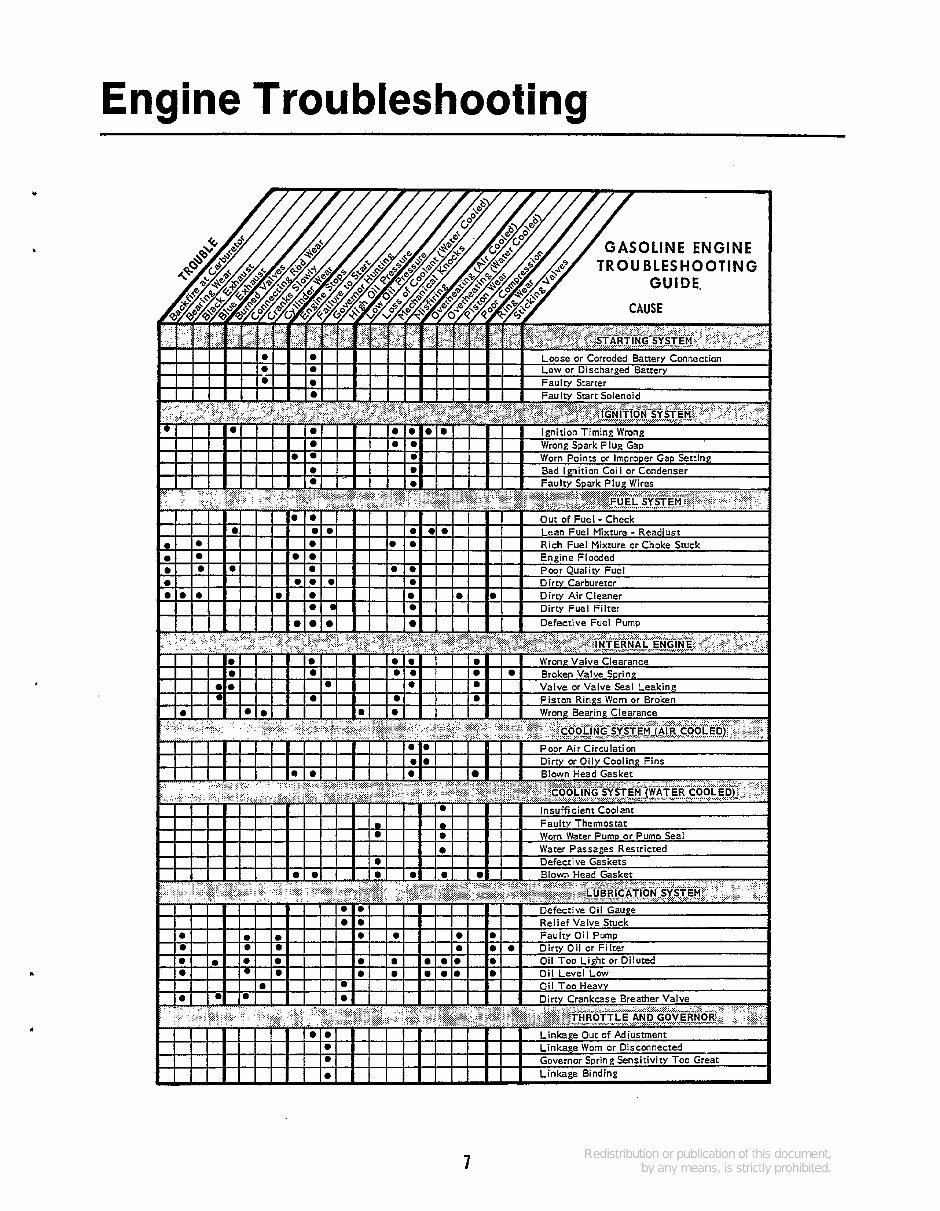
Engine Troubleshooting . 7
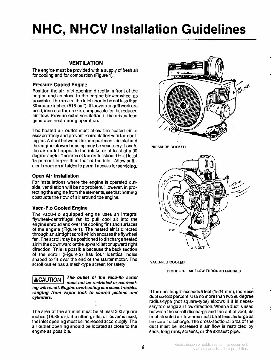
NHC, NHCV Installation Guidelines VENTILATION The engine must be provided with a supply of fresh air for cooling and for combustion (Figure 1). Pressure Cooled Engine Position the air inlet opening directly in front of the engine and as close to the engine blower wheel as possible.Theareaoftheinletshould be not lessthan 80 square inches (516 cm'). If louversor grill work are used, increasethearea to compensateforthe reduced air flow. Provide extra ventilation if the driven load generates heat during operation. The heated air outlet must allow the heated air to escape freely and prevent recirculation with thecool- ing air. A duct betweenthe compartment air inlet and theengine blower housing may be necessary. Locate the air outlet opposite the intake or at least at a 90 degree angle. The area of the outlet should be at least 15 percent larger than that of the inlet. Allow suffi- cient room on all sides to permit access forservicing. Open Air Installation For installations where the engine is operated out- side, ventilation will be no problem. However, in pro- tecting theengine from theelements, seethat nothing obstructs the flow of air around the engine. Vacu-Flo Cooled Engine The vacu-flo equipped engine uses an integral flywheel-centrifugal fan to pull cool air into the engine shroud and over the cooling finsand surfaces of the engine (Figure 1). The heated air is directed through an airtight scroll which encasestheflywheel fan. The scroll may be positionedto discharge heated air in the downward orthe upward left or upward right direction. This is possible because the back section of the scroll (Figure2) has four identical holes shaped to fit over the end of the starter motor. The scroll outlet has a mesh-type screen for safety. . The ouflef of the vacu-flo scroll @!@%I musf nof be resfricfed or overheaf- ing will result. Engine overhea fing can cause troubles ranging from vapor lock to scored pistons and cylinders. The area of the air inlet must be at least 300 square inches (19.35 m2). If a filter, grille, or louver is used, the inlet opening must be increasedaccordingly. The air outlet opening should be located as close to the engine as possible. PRESSURE COOLED m PRESSURE COOLED m VACU-FLO COOLED FIGURE 1. AIRFLOW THROUGH ENGINES Iftheduct length exceeds5feet (1524 mm), increase duct size 30 percent. Use no morethan two 90 degree radius-type (not square-type) elbows if it is neces- sary to change air flow direction. When aduct is used between the scroll discharge and the outlet vent, its unobstructedairflow area must be at least as large as the scroll discharge. The cross-sectional area of the duct must be increased if air flow is restricted by ends, long runs, screens, or the exhaust pipe. b 8
The Onan Cummins NHC, NHCV, NH Series Generators Service Repair Manual is a comprehensive workshop manual that provides detailed servicing instructions for professional mechanics and DIY enthusiasts. This manual offers complete information on repair, servicing, preventative maintenance, and troubleshooting procedures for Onan Cummins Generators. It features step-by-step instructions, photos, and illustrations to guide you through the entire repair process, making it an indispensable source of detailed maintenance and repair information.
It covers the following Onan Cummins Generator Models:
NHC SPEC E
NHCV SPEC E
NH (RV) SPEC J-P
Key features of this manual include:
Instant access with no waiting time
Easy navigation for quick identification of service repair procedures
Detailed illustrations, exploded diagrams, drawings, and photos to guide you through every service repair procedure
File Format: PDF
Pages: 64
Printable: Yes
Language: English
Subjects covered in this Onan Cummins Generator Complete Service Shop Manual:
ENGINE AND ACCESSORIES
GENERATOR
SAFETY PRECAUTIONS
CONTROL PANEL
OPERATION
PERIODIC MAINTENANCE
GENERATOR SET CONTROL
SPECIFICATIONS
WIRING DIAGRAM
After purchasing the service manual, you can instantly view and print it whenever needed. This manual is a valuable resource for understanding, caring for, and servicing your Onan Cummins Generator, ultimately lowering the repair and maintenance costs.
Recently Viewed
5,521,897Happy Clients
2,594,462eManuals
1,120,453Trusted Sellers
15Years in Business
Price:
Actual Price:
Onan NHC, NHCV, NH Series Service Manual Cummins Onan Generator Repair Book 940-0751