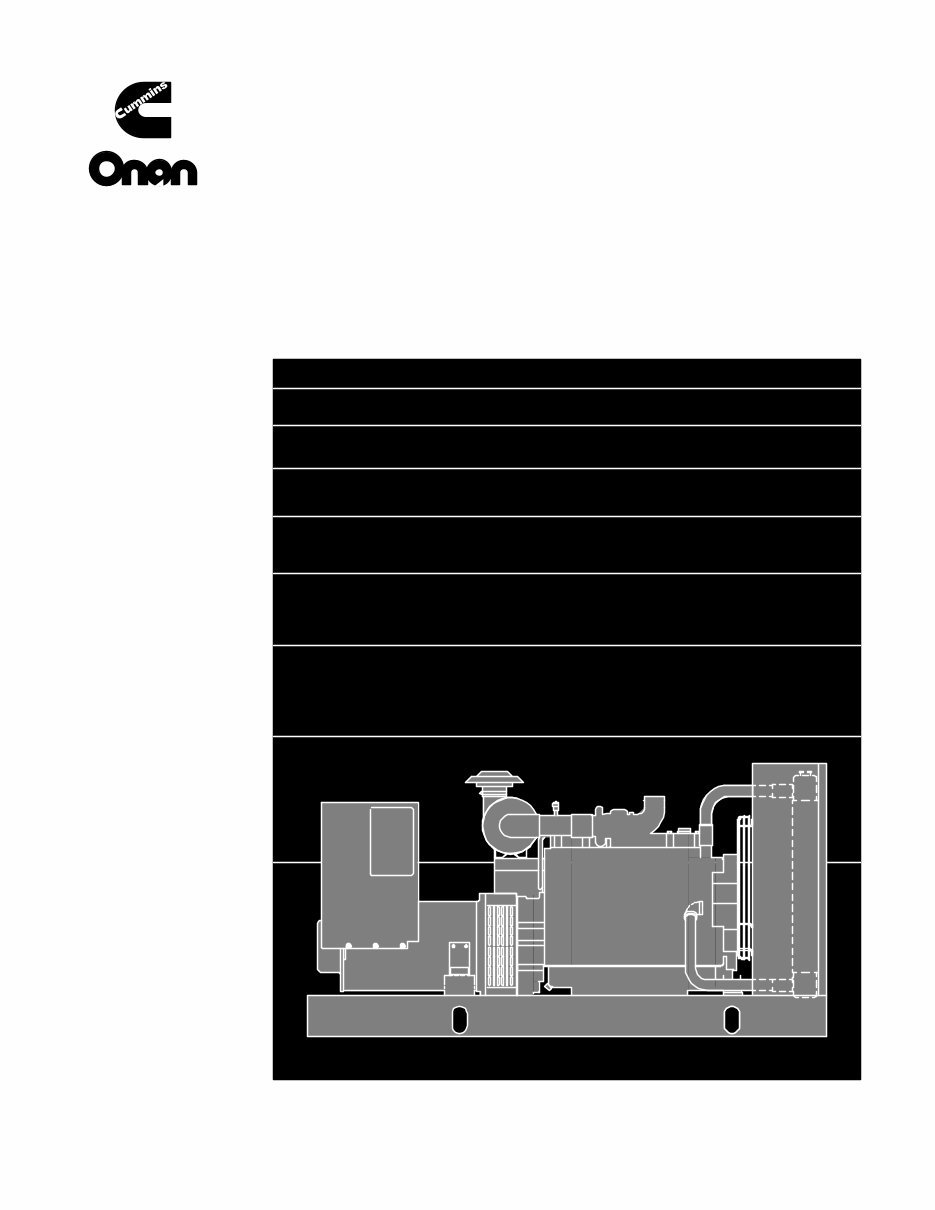
Models Begin Spec DGBB E DGBC D DGCA M DGCB M DGCC A DGDA L DGDB L DGEA K DGFA K DGFB K DGFC A GENERATOR SETS Service Manual Printed in U.S.A. 960Ć0510B 10Ć98 Detector/Sentinel Controls
Page 2 of 4 Supplement 960-1056 Date: 11Ć09Ć00 Insert with - Title: Service Numbers: See Supplement Use PURPOSE This supplement contains information for the revised Engine Control Monitor (ECM) board. The revised ECM board contains LED’s and termi- nal board TB3 to aid in genset control troubleshooting. A selection jumper has also been added, which controls how the SWITCH OFF indicator op- erates. Both ECM boards are identical in function and how they connect electri- cally. The present ECM board description in Section 3 of the Service manual has not changed, other than the additional information describing the new components and a figure showing the location of the new compo- nents. SUPPLEMENT USE Refer to the corresponding pages/headings of your manual and write “IM- PORTANT: REFER TO SUPPLEMENT”. Please keep this supplement with the following Service manuals: 928-0502B 928-0506 960-0504A 960-0505 960-0510B
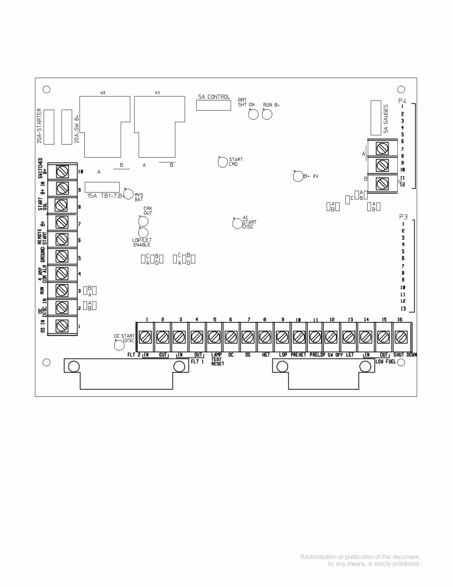
3-1 ENGINE CONTROL MONITOR (A11) The heart of the engine control system is the engine control monitor (ECM) (Figure 3-5). It is a printed circuit board assembly mounted on the back wall of the control box. It starts and stops the engine in response to the control panel switches, engine sensors and remote control signals. Note that there are two versions of the ECM board and that they both perform the same functions. They only differ in that one version contains additional components, which are, LED’s (DS1 – DS9), terminal board (TB3) and function selection jumper W10. Figure 3-5 illustrates the ECM version which contains the additional components. LED’s DS1 through DS9 The ECM LED’s are provided as an aid in troubleshooting the control circuitry. The LED’s indicate the following conditions: LED STATUS WHEN ILLUMINATED DS1 B+ is connected to ECM and fuse F4 is good. DS2 RUN relay is energized. DS3 Start Command signal enabled. DS4 Crank signal enabled. DS5 DC Starter Disconnect signal enabled. DS6 AC Starter Disconnect signal enabled. DS7 LOP/HET signal active (time delay circuit has timed-out). DS8 Reverse battery voltage. DS9 Remote Shutdown signal active (grnd at TB2-16)
3-2 Terminals and Connectors See Pages 9-5 through 9-9 for the appropriate connection and schematic drawings for the DC control system. See Page 9-10 for typical customer connections at terminal boards TB1 and TB2 on the ECM and page 9-11 if the set is also equipped with the auxiliary relay board. TB3 provides an alternative direct connection to the ECM for the RUN/STOP/REMOTE switch for troubleshooting or if desired, customer connection. TB3-1 = REMOTE TB3-2 = RUN TB3-3 = STOP Fuses The ECM has five replaceable fuses to protect it from overloads and ground faults. They are: F1 Starter solenoid circuit, 20 amps. F2 Fuel solenoid (switched B+) circuits, 20 amps. F3 Continuous B+ out to remote circuits, 15 amps. F4 ECM circuits, 5 amps. F5 Engine gauge circuits, 5 amps. Function Selection Jumpers ECM board has six selection jumpers that can be repositioned to provide the following timed or non-timed warnings or timed or non-timed shutdowns with warnings and control of the SWITCH OFF indicator: W1 Jumper Position (jumper W8 must be in the B position): A Non-timed warning under FLT 2 conditions. B Non-timed shutdown under FLT 2 conditions. C Timed warning under FLT 2 conditions. D Timed shutdown under FLT 2 conditions. W2 Jumper Position (jumper W9 must be in the B position): A Non-timed warning under FLT 1 conditions. B Non-timed shutdown and under FLT 1 conditions. C Timed warning under FLT 1 conditions. D Timed shutdown under FLT 1 conditions. W6 Jumper Position: A Warning under Pre-High Engine Temperature conditions. B Shutdown under Pre-High Engine Temperature conditions. W7 Jumper Position: A Warning under Pre-Low Oil Pressure conditions. B Shutdown under Pre-Low Oil Pressure conditions. W8 Jumper Position: A Warning while running or during standby under FLT 2 conditions. B Allows selection of functions with W1 jumper. W9 Jumper Position: A Warning while running or during standby under FLT 1 conditions. B Allows selection of functions with W2 jumper. W10 Jumper Position (SWITCH OFF Indicator): A Flashing B Constant ON C OFF
Cummins Onan Generator Sets Service & Repair Manual Collection
Models covered:
Detector/Sentinel Controls Generator Sets
PowerCommand (2100 Series) Control Generator Sets
PowerCommand (3100 Series) Control Generator Sets
This Cummins Onan Generator Sets Service & Repair Manual Collection is an essential resource for maintaining and repairing a wide range of generator sets with Detector/Sentinel and PowerCommand Controls. It is compiled to facilitate technicians with various models, ensuring a high level of accuracy in troubleshooting, diagnosing, and resolving mechanical or electrical faults.
This exhaustive compilation provides detailed guidance on repair techniques, service procedures, and maintenance schedules. It includes a comprehensive set of wiring diagrams, parts catalogs, and operational schematics, which are crucial for understanding the sophisticated control systems integrated into these generator sets.
Tailored to adhere to the manufacturer's stringent standards, this manual offers an in-depth look at the functionality and servicing of both the 2100 and 3100 series PowerCommand control systems. From routine service tasks to complex repairs, this manual provides the technical insights required to ensure the reliability, efficiency, and longevity of Cummins Onan Generator Sets. With clear, step-by-step instructions and supporting visuals, technicians can confidently address a broad spectrum of potential issues and service requirements.
Printable: Yes Language: English Compatibility: Pretty much any electronic device, incl. PC & Mac computers, Android and Apple smartphones & tablet, etc. Requirements: Adobe Reader (free)
Reviews
Q&A
Recently Viewed
5,521,897Happy Clients
2,594,462eManuals
1,120,453Trusted Sellers
15Years in Business
Price:
Actual Price:
Cummins Onan Generator Sets OEM Service & Repair Manual Collection




 Lifetime Access




