Service Manual
English – Original Instructions 1-2010
X1.3 and X2.5 Generator Sets
with PowerCommand
®
1.1 Controller
C8 D5
C11 D5
C12 D6
C16 D6
C17 D5
C20 D6
C22 D5
C28 D5
A029U125 (Issue 2)
PowerCommand® 1.1 Publication A029U125
Models C8 D5 – C28 D5 Issue 2 - 1-2010
© Copyright Cummins Power Generation page 3
Table of Contents
SECTION TITLE PAGE
1 IMPORTANT SAFETY INSTRUCTIONS 5
2 INTRODUCTION 7
2.1 About this Manual 7
2.2 System Overview 7
2.3 Test Equipment 7
2.4 How to Obtain Service 7
3 CONTROL PANEL OPERATION 8
3.1 General 8
3.2 Operating Modes 9
3.3 Control Panel 10
3.4 System Messages 13
3.5 Selecting Auto, Manual Run and OFF Modes 15
3.6 Operator Menus 18
3.7 Service Menus 21
3.8 History/About Menu 23
3.9 Screen Adjust Menu 25
3.9.1 Fault History Menu 26
4 CIRCUIT BOARD 28
4.1 General 28
4.2 Base Board 30
5 TROUBLESHOOTING 31
5.1 General 31
5.2 InPower Service Tool 31
5.3 Network Applications and Customer Inputs 31
5.4 Safety Consideration 32
5.5 Reading Fault Codes 32
5.6 Troubleshooting Procedure 33
PowerCommand® 1.1 Publication A029U125
Models C8 D5 – C28 D5 Issue 2 - 1-2010
page 4 © Copyright Cummins Power Generation
SECTION TITLE PAGE
6 CONTROL ADJUSTMENT AND SERVICE 52
6.1 General 52
6.2 Circuit Board Removal/Replacement 53
6.3 Setup Menu 54
6.4 Genset Service Menus 55
6.5 Genset Service Submenus 57
6.6 Automatic Voltage Regulator Submenus 63
6.7 Electronic Governor Submenus 65
6.8 Customer I/O Submenus 67
6.9 Metering Submenus 69
6.9.1 Annunciator Submenus 71
6.9.2 Genset Setup Submenus 77
6.9.3 Genset Submenus 80
6.9.4 Voltage Protection Submenus 86
6.9.5 Current Protection Submenus 88
6.9.6 Engine Protection Submenus 90
6.9.7 TB1 Base Board Customer Connections 96
6.9.8 Engine Sensors. 97
6.9.9 Magnetic Speed Pickup Unit (MPU) Installation 98
6.9.0 Current Transformer (CT) Installation 99
7 SERVICING THE GENERATOR 100
7.1 Testing the Generator 100
7.2 Generator/Base Board Isolation Procedure 101
7.2.1 Generator Disassembly 108
7.2.2 Generator Reassembly 110
8 Generator Specifications 112
9 WIRING DIAGRAMS 114
9.1 General Information 114
PowerCommand® 1.1 Publication A029U125
Models C8 D5 – C28 D5 Issue 2 - 1-2010
© Copyright Cummins Power Generation page 5
SECTION 1 – IMPORTANT SAFETY INSTRUCTIONS
SAVE THESE INSTRUCTIONS – This manual
contains important instructions that should be followed
during installation and maintenance of the generator
and batteries.
Before operating the generator set (genset), read the
Operator’s Manual and become familiar with it and the
equipment. Safe and efficient operation can be
achieved only if the equipment is properly operated
and maintained. Many accidents are caused by failure
to follow fundamental rules and precautions.
The following symbols, found throughout this manual,
alert you to potentially dangerous conditions to the
operator, service personnel, or the equipment.
This symbol warns of
immediate hazards which will result in
severe personal injury or death.
This symbol refers to a
hazard or unsafe practice which can
result in severe personal injury or death.
This symbol refers to a
hazard or unsafe practice which can
result in personal injury or product or
property damage.
FUEL AND FUMES ARE FLAMMABLE
Fire, explosion, and personal injury or death can result
from improper practices.
• DO NOT fill fuel tanks while engine is running,
unless tanks are outside the engine
compartment. Fuel contact with hot engine or
exhaust is a potential fire hazard.
• DO NOT permit any flame, cigarette, pilot light,
spark, arcing equipment, or other ignition source
near the generator set or fuel tank.
• Fuel lines must be adequately secured and free
of leaks. Fuel connection at the engine should be
made with an approved flexible line. Do not use
zinc coated or copper fuel lines with diesel fuel
• Be sure all fuel supplies have a positive shutoff
valve.
• Be sure battery area has been well-ventilated
prior to servicing near it. Lead-acid batteries emit
a highly explosive hydrogen gas that can be
ignited by arcing, sparking, smoking, etc.
EXHAUST GASES ARE DEADLY
• Provide an adequate exhaust system to properly
expel discharged gases away from enclosed or
sheltered areas and areas where individuals are
likely to congregate. Visually and audibly inspect
the exhaust daily for leaks per the maintenance
schedule. Make sure that exhaust manifolds are
secured and not warped. Do not use exhaust
gases to heat a compartment.
• Be sure the unit is well ventilated.
• Engine exhaust and some of its constituents are
known to the state of California to cause cancer,
birth defects, and other reproductive harm.
MOVING PARTS CAN CAUSE SEVERE PERSONAL
INJURY OR DEATH
• Keep your hands, clothing, and jewelry away
from moving parts.
• Before starting work on the generator set,
disconnect battery charger from its AC source,
then disconnect starting batteries, negative (–)
cable first. This will prevent accidental starting.
• Make sure that fasteners on the generator set are
secure. Tighten supports and clamps, keep
guards in position over fans, drive belts, etc.
• Do not wear loose clothing or jewelry in the
vicinity of moving parts, or while working on
electrical equipment. Loose clothing and jewelry
can become caught in moving parts.
• If adjustment must be made while the unit is
running, use extreme caution around hot
manifolds, moving parts, etc.
DO NOT OPERATE IN FLAMMABLE AND
EXPLOSIVE ENVIRONMENTS
Flammable vapor can cause an engine to overspeed
and become difficult to stop, resulting in possible fire,
explosion, severe personal injury and death. Do not
operate a genset where a flammable vapor
environment can be created by fuel spill, leak, etc.,
unless the genset is equipped with an automatic
safety device to block the air intake and stop the
engine. The owners and operators of the genset are
solely responsible for operating the genset safely.
Contact your authorized Cummins Power
Generation distributor for more information.
DANGER
WARNING
CAUTION
Contact your authorized Cummins Power Generation distributor for more information
PowerCommand® 1.1 Publication A029U125
Models C8 D5 – C28 D5 Issue 2 - 1-2010
page 6 © Copyright Cummins Power Generation
ELECTRICAL SHOCK CAN CAUSE SEVERE
PERSONAL INJURY OR DEATH
• Remove electric power before removing
protective shields or touching electrical
equipment. Use rubber insulative mats placed
on dry wood platforms over floors that are metal
or concrete when around electrical equipment.
Do not wear damp clothing (particularly wet
shoes) or allow skin surface to be damp when
handling electrical equipment. Do not wear
jewelry. Jewelry can short out electrical contacts
and cause shock or burning.
• Use extreme caution when working on electrical
components. High voltages can cause injury or
death. DO NOT tamper with interlocks.
• Follow all applicable state and local electrical
codes. Have all electrical installations performed
by a qualified licensed electrician. Tag and lock
open switches to avoid accidental closure.
• DO NOT CONNECT GENERATOR SET DI-
RECTLY TO ANY BUILDING ELECTRICAL
SYSTEM. Hazardous voltages can flow from the
generator set into the utility line. This creates a
potential for electrocution or property damage.
Connect only through an approved isolation
switch or an approved paralleling device.
GENERAL SAFETY PRECAUTIONS
• Coolants sunder pressure have a higher boiling
point than water. DO NOT open a radiator or
heat ex-changer pressure cap while the engine
is running. To prevent severe scalding, let
engine cool down before removing coolant
pressure cap. Turn cap slowly, and do not open
it fully until the pressure has been relieved.
• Used engine oils have been identified by some
state or federal agencies as causing cancer or
reproductive toxicity. When checking or
changing engine oil, take care not to ingest,
breathe the fumes, or con-tact used oil.
• Keep multi-class ABC fire extinguishers handy.
Class A fires involve ordinary combustible
materials such as wood and cloth; Class B fires,
combustible and flammable liquid fuels and
gaseous fuels; Class C fires, live electrical
equipment. (ref. NFPA No. 10).
• Make sure that rags are not left on or near the
generator set.
• Make sure generator set is mounted in a
manner to prevent combustible materials from
accumulating under or near the unit.
• Remove all unnecessary grease and oil from
the unit. Accumulated grease and oil can cause
over-heating and engine damage which present
a potential fire hazard.
• Keep the generator set and the surrounding
area clean and free from obstructions. Remove
any debris from the set and keep the floor clean
and dry.
• Do not work on this equipment when mentally
or physically fatigued, or after consuming any
alcohol or drug that makes the operation of
equipment unsafe.
• Substances in exhaust gases have been
identified by some state or federal agencies as
causing cancer or reproductive toxicity. Take
care not to breath or ingest or come into contact
with exhaust gases.
• Do not store any flammable liquids, such as
fuel, cleaners, oil, etc., near the generator set.
A fire or explosion could result.
• Wear hearing protection when going near an
operating generator set.
• To prevent serious burns, avoid contact with hot
metal parts such as radiator system, turbo
charger system and exhaust system.
KEEP THIS MANUAL NEAR THE GENSET FOR EASY REFERENCE
PowerCommand® 1.1 Publication A029U125
Models C8 D5 – C28 D5 Issue 2 - 1-2010
© Copyright Cummins Power Generation page 7
SECTION 2 – INTRODUCTION
2.1 ABOUT THIS MANUAL
This manual provides troubleshooting and
repair information regarding the
PowerCommand® 1302Control (PCC) and
generators for the generator sets (gensets)
listed on the front cover. Engine service
instructions are in the applicable engine
service manual. Operating and maintenance
instructions are in the applicable Operator’s
Manual.
This manual does not have instructions for
servicing printed circuit board assemblies.
After determining that a printed circuit board
assembly is faulty, replace it, do not repair it.
Attempts to repair a printed circuit board can
lead to costly damage to the equipment.
This manual contains basic (generic) wiring
diagrams and schematics that are included to
help in troubleshooting. Service personnel
must use the actual wiring diagram and
schematic shipped with each unit. The wiring
diagrams and schematics that are maintained
with the unit should be updated when
modifications are made to the unit.
Read Important Safety Instructions and
carefully observe all instructions and
precautions in this manual.
2.2 SYSTEM OVERVIEW
The PCC is a microprocessor-based control for
Cummins Power Generation generator sets.
All generator set control functions are
contained on one circuit board (Base board).
The Base board provides fuel control, main
alternator voltage output regulation and
complete generator set control and monitoring.
The operating software provides control of the
generator set and its performance
characteristics, and displays performance
information on a digital display panel. It
accepts menu-driven control and set-up input
from the push button switches on the front
panel.
2.3 TEST EQUIPMENT
To perform the test procedures in this manual,
the following test equipment must be available
True RMS meter for accurate measurement of
small AC and DC voltages. Fluke models 87 or
8060A are good choices.
Grounding wrist strap to prevent circuit
board damage due to electrostatic
discharge (ESD).
Battery Hydrometer.
Jumper Leads.
Tachometer or Frequency Meter.
Wheatstone Bridge or Digital Ohmmeter.
Variac.
Load Test Panel.
Megger or Insulation Resistance Meter.
InPower™ Service Tool (PC based genset
service tool).
PCC1302 Interface Kit (Used with InPower
Service Tool)
2.4 HOW TO OBTAIN SERVICE
Always give the complete Model, Specification
and Serial number of the generator set as
shown on the nameplate when seeking
additional service information or replacement
parts. The nameplate is located on the front of
the control panel.
Incorrect service or
replacement of parts can result in severe
personal injury or death, and/or equipment
damage. Service personnel must be trained
and experienced to perform electrical and
mechanical service. Read and follow
Important Safety Instructions on pages iii
and iv.
WARNING
PowerCommand® 1.1 Publication A029U125
Models C8 D5 – C28 D5 Issue 2 - 1-2010
page 8 © Copyright Cummins Power Generation
SECTION 3 – OPERATOR PANEL OPERATION
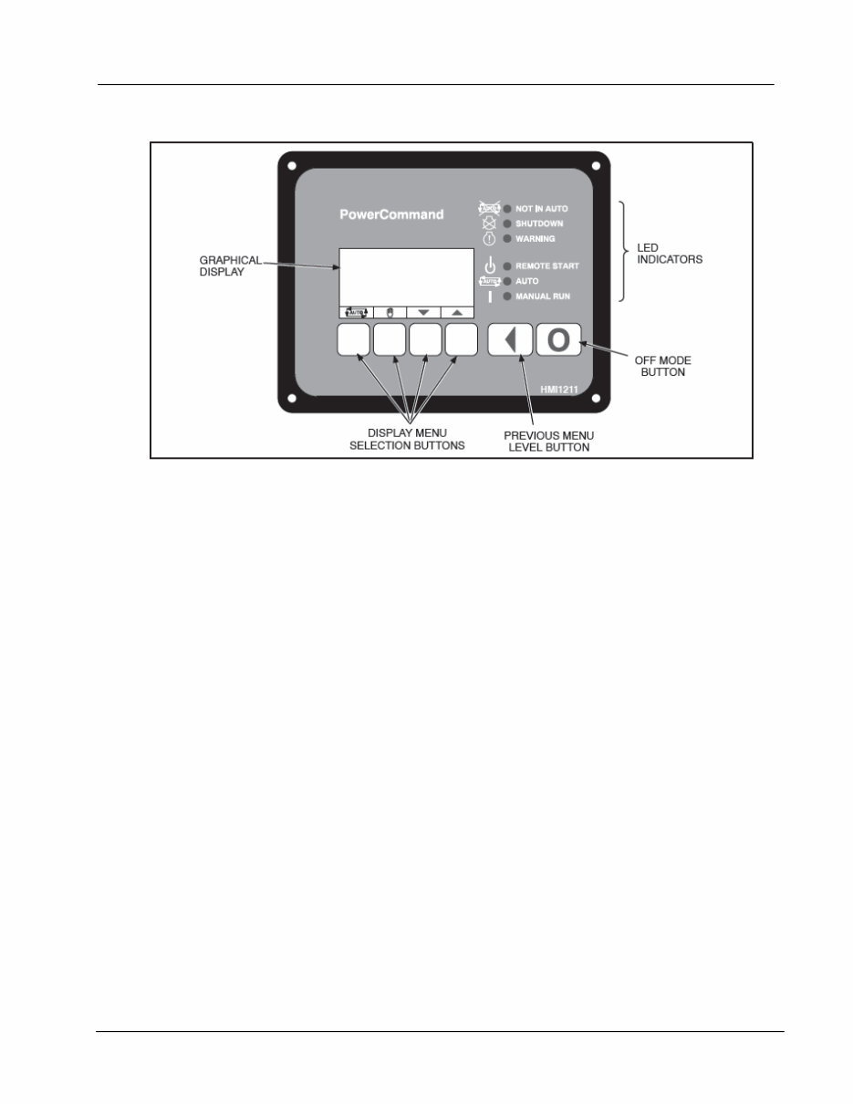
FIGURE 2-1. 1302 OPERATOR PANEL
3.1 GENERAL
This section includes information on the
following.
• Local Status Output Indicator
• Operating Modes
• Operator Panel Description
• Operator Panel System Messages
• Description of Fault and Status Codes
• Adjusting Values and Saving the Changes
• Basic Operator Menus
• Selecting Auto, Manual Run, and Off
Modes
• Service Menus
• History/About Menus
• Fault History Menu
• Screen Adjust Menu
LOCAL STATUS OUTPUT INDICATOR
If your installation includes a status indicator
lamp that flashes genset status and shutdown
fault codes, the following describes how to
interpret the status indicator light.
• Constant Fast Flashing = This occurs during
preheat (when used) and while the generator
set is starting.Constant On = The genset is
running.
• Intermittent Flashing = A genset shutdown
fault condition exists. All of the shutdown
faults described in Table 4-2 can be
announced with a status indicator lamp.
For four-digit shutdown fault codes , the first
digit in the code is flashed, followed by a half
second pause, then the second digit is flashed,
followed by a half-second pause, then the third
digit is flashed, followed by a half-second
pause, and then the fourth digit is flashed,
followed by a two-second pause.
NOTE: Only the last shutdown fault is flashed.
When a fault is corrected, the Manual Run/Off/
Auto switch must be placed in the Off position
to reset the control.
Under all other indications, the status lamp is
off.
PowerCommand® 1.1 Publication A029U125
Models C8 D5 – C28 D5 Issue 2 - 1-2010
© Copyright Cummins Power Generation page 9
3.2 OPERATING MODES
The 1302 control works with a Manual
Run/Off/Auto switch, used to control genset
operating modes. This capability is located
either in the harness (switch) or is integrated
into the operator panel included in this kit.
Off Mode
When in Off mode, the control does not allow
the genset to start. If the genset is already
running and the control is set to Off, it initiates a
normal shutdown sequence. When in Off mode,
all active faults are reset.
Manual Run Mode
When in Manual Run mode, the genset starts
and continues to run until the control is put into
the Off mode. While in Manual Run mode, any
remote start signal is ignored.
Auto Mode
When in Auto mode, the control allows the
genset to be started with a remote start signal
only. When in Auto mode, the genset can start
at any time. When a remote start signal is
received, the genset starts after the time delay
start and time delay preheat (if programmed)
are completed. If the genset is running in Auto
mode and the Off button is pressed, the control
immediately stops the genset and the control
transitions to the Off mode. When all remote
start signals are removed, the control performs
a normal shutdown sequence which may
include a time delay stop.
Emergency Stop Mode
When the optional emergency stop button is
used, it immediately shuts down the generator
set, bypassing any time delay stop. The red
Shutdown LED lights and Fault Code 1433 or
1434 − Emergency Stop is either displayed
(installations with a operator panel) or flashed
(installations with a status indicator lamp). To
reset the control, close (disable) the emergency
stop button and either press the (Off) button
(installations that include a operator panel) or
move the control switch to the OFF position
(installations with a Manual Run/Off/Auto
switch).
Sleep Mode
The 1302 series control enters a low power
(sleep) mode of operation where the current
draw is not greater than 60 milliamps (DC) at
normal battery voltage levels. The control is set
to enter sleep mode after five minutes in the Off
or Auto mode (configurable). Sleep mode can
only be disabled by installing a jumper between
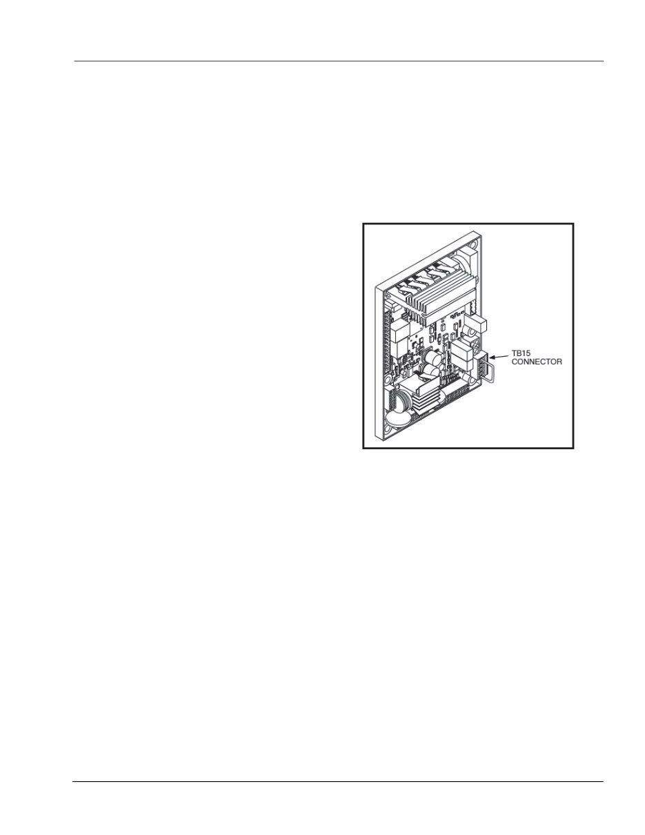
TB15-1 and TB15-5 (the TB15 connector is
shown in Figure 2-2).
FIGURE 2-2. TB15 CONNECTOR WITH JUMPER
The control will not enter the sleep mode if
there are any active, unacknowledged
shutdown faults, if the control is in the Manual
Run mode. Once in sleep mode, the 1302
series control will wake up when one of the
following wakeup signals are received.
• Local E-Stop − Active when switch is
open
• Remote E-Stop − Active when switch is
open
• Manual Start
• PCCNet System Wakeup
• Remote Start
• Auto Mode (If Configured)
• Configurable Input #3
• Configurable Input #4
PowerCommand® 1.1 Publication A029U125
Models C8 D5 – C28 D5 Issue 2 - 1-2010
page 10 © Copyright Cummins Power Generation
3.3 CONTROL PANEL
Figure 2-1 shows the features of the front panel. It
includes six LED indicators, the graphical display,
and six buttons used to navigate through the
menus and adjust parameters.
Graphical Display
This graphical display is used to view menus of the
menu-driven operating system. The bottom of the
graphical display indicates the functions that are
available by pressing the four selection buttons.
Re-fer to the menu trees later in this section.
System messages (communication, event, and
fault) are also shown on the graphical display. For
more information, see System Messages later this
section.
Display Text / Symbolic Versions
This graphical display can be set up to show either
text or symbolic versions for fault messages, some
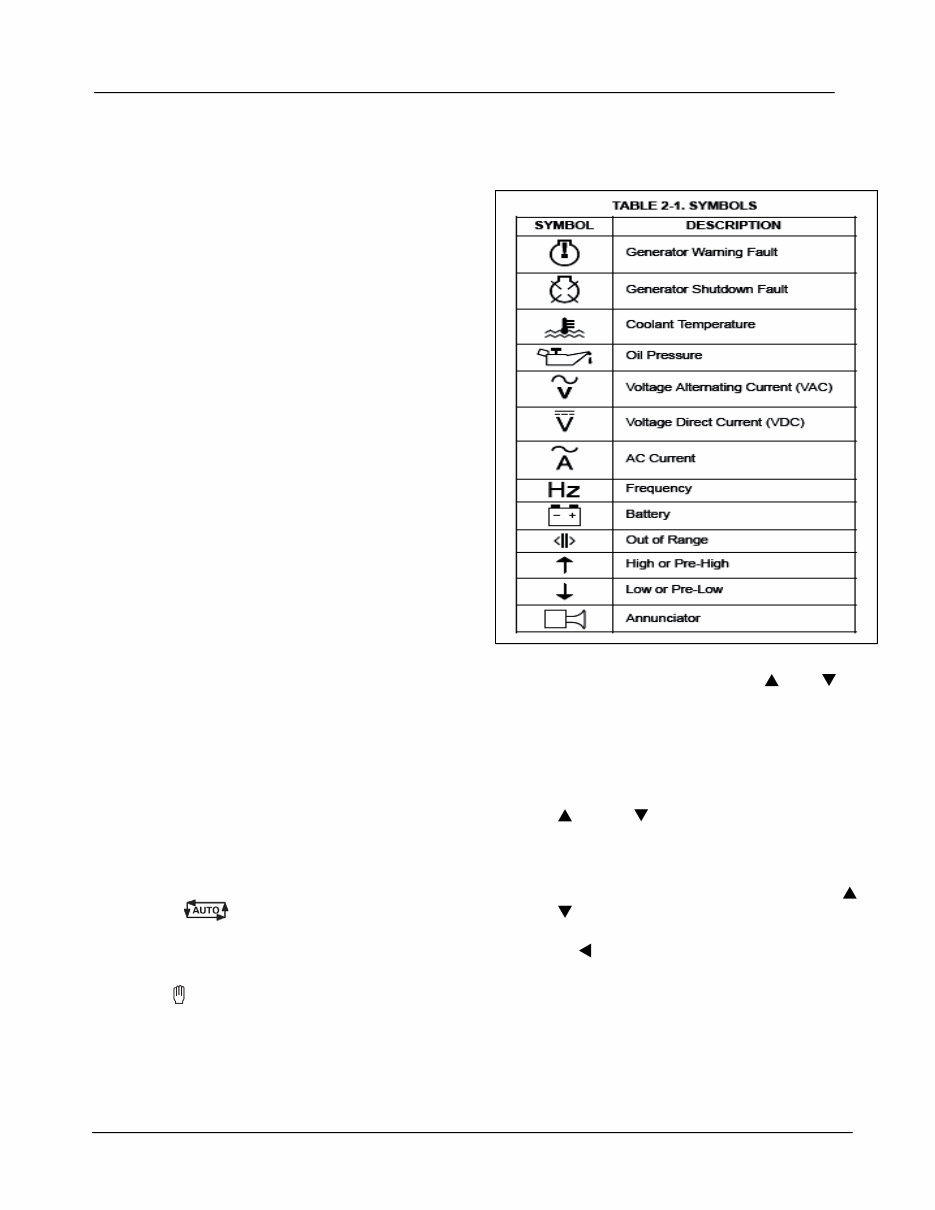
Operator menus, and the Mode Change menu. A
description of commonly used symbols used are
included in Table 2-1. Combinations of symbols are
used to display some fault conditions. Additional
specialized symbols are also used for some
faults(see Section 4 ).When shipped from the
factory, symbolic display is selected. (Refer to
Setup menu in Section 5 to change to text or
symbolic display.)
Display Menu Selection Buttons
Four momentary soft-key buttons are used to
step through the various menus and to adjust
parameters. These selection buttons are
“active” when a word or symbol in the graphical
display is shown above the button. Some
submenus do not include any active buttons.
The function of the four selection buttons varies
with each menu.
When the symbol is displayed, the
selection button can be used to switch to Auto
mode.
When the symbol is displayed, the selection
button can be used to switch to Manual Run
mode.
When the up and down triangles ( and ) are
displayed, the selection buttons are used to
navigate between a series of submenus.
NOTE: When any Operator menu (Figure 2-12 is
displayed, a series of Service menu scan
be viewed by simultaneously pressing the
and selection buttons for two
seconds.
NOTE: When a fault is displayed, it can be cleared
from the front panel by pressing the or
button.
When a symbol is displayed, the selection
button can be used to abort the Auto or Manual
Run mode and return to the Operator menu that
was displayed before the Auto or Manual Run
mode was selected.
You're Reading a Preview
What's Included?
Lifetime Access
Access PDF Contents & Bookmarks
Print one or all pages of your manual






 Lifetime Access




