Generator Fundamentals Basic Electricity 3 Magnetism and Electricity 3 Electro-Motive Force 4 Electromagnetism 7 Direct Current (DC) 8 Alternating Current (AC) 8 Volt 10 Ampere 10 Ohm 10 Ohm’s Law 11 The Watt 11 Electrical Formulas 12 The Series Circuit 13 The Parallel Circuit 13 The Series-Parallel Circuit 14 Simple Alternator 17 Simple Alternator Operation 17 Generator Components And Systems Generator Components 19 Rotor Assembly 20 Stator Assembly 21 Switches 23 Fuses 26 Circuit Breakers 26 Solenoids 27 Relays 28 Resistors 29 Transformers 31 Condensers 32 Rectifiers 33 Transistors 34 Brushes and Brush Holders 35 Voltage Regulator 37 Generator Systems 41 Revolving Field Excitation Methods 42 Direct Excitation 42 The Brushless Excitation Method 44 Field Boost Assembly 45 Power Factor 46 Oil Pressure Switch On “GN” Engines 49 Typical Automatic Idle Control System 50 Early V-Twin Engine Idle Control 51 Idle Control on “GN” 190, 220, 320, 360, & 410 ENGINES 51 “XL” And “MC” Idle Control On 480 & 570 V-Twin Engines 53 1 GENERAC ® PORTABLE PRODUCTS Table of Contents Portable Generator Familiarization & Troubleshooting Guide
Generator Diagnostics And Adjustments Troubleshooting Idle Controls 56 Troubleshooting Flowchart For “Direct Excited” (Brush Type) Generators 68 Troubleshooting Flowchart For (Brush Type) Generators With “Two Board” Regulation 76 Troubleshooting Flowchart For “Sincro® Wound” (Brushless Type) Generators 84 Voltage Regulator Adjustments 90 Generator Assemblies Generac® Wound Generators 94 Disassembly 94 Assembly 101 Sincro® Wound Generators 109 Disassembly 109 Assembly 112 Appendix A Generac® Torque Table 117 Generac® Receptacles And Plugs 118 Glossary 120 2 GENERAC ® PORTABLE PRODUCTS Table of Contents Portable Generator Familiarization & Troubleshooting Guide
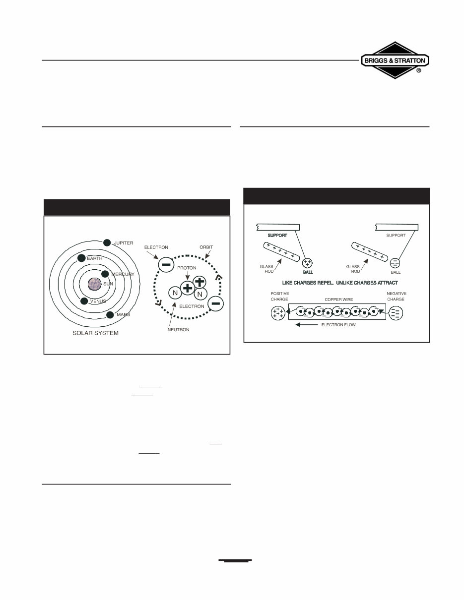
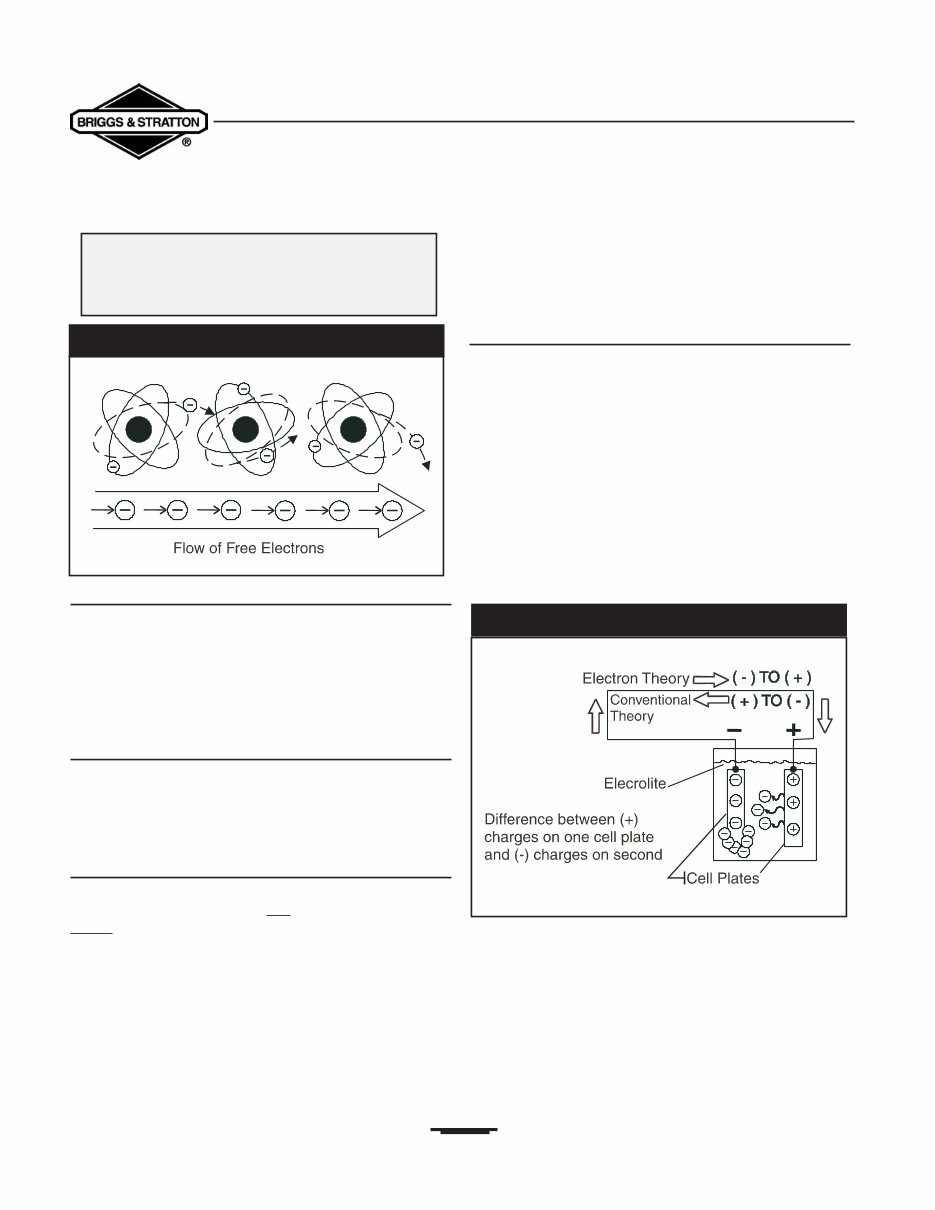
BASIC ELECTRICITY Section 1 • Generator Fundamentals Portable Generator Familiarization & Troubleshooting Guide 3 The Atom All matter is made up of atoms.An atom may be compared to a solar system that has several planets revolving around the sun.There are more than 100 different kinds of atoms. The various atoms combined together form all known substances. The structure of the helium atom is shown in Figure 1.1. Negatively (-) charged particles called electrons revolve around a positively charged nucleus.The nucleus is made up of both protons, which have a positiv e (+) electrical charge, and neutrons, which have a neutral (N) electrical charge. The negative and positive particles that make up an atom act much like the north and south poles of a magnet, in which the north pole is positive (+) and the south pole is negative (-). Every child who has played with a magnet knows that lik e poles repel each other and unlik e poles attract each other. Magnetism and Electricity Like the poles of a magnet, atomic particles with the same charges repel each other and the particles with different charges attract each other. In a normal atom, the positive charge of the nucleus exactly balances the negative charge of the electrons that rotate around it. Borrowing Of Electrons If an atom loses electrons, the positive (+) charge of the nucleus and the negative (-) charge of the electrons revolving around it is no longer balanced.The atom then becomes positively charged.The natural tendency of the positively charged atom is to attract any other negative charges, such as an electron from another atom (Figure 1.2). The positively charged atom attempts to return to a balanced (or neutral) state and will “borrow” an electron from a neighboring atom.When an atom borrows an electron from its neighbor, the neighbor then becomes positively charged.This starts a “chain reaction” in which each atom in turn borrows an electron from its neighboring atom. This borrowing of electrons creates a flow of current that continues until all the atoms have achieved a state of balance. Figure 1.3 illustrates the transfer of electrons from one atom to the next and the resulting flow of free electrons that occurs.This may be difficult to visualize, unless you remember that an electron is so small that it finds great empty spaces for free travel, even in a solid substance. Figure 1.1 — The Helium Atom Figure 1.2 — Magnetism and Electricity
Section 1 • Generator Fundamentals Portable Generator Familiarization & Troubleshooting Guide Conductors and Non-Conductors Some materials (such as copper or silver) will readily transfer electrons from atom to atom.These materials are called conductors. Other materials hold their electrons very tightly and are said to have “bound” electrons.These non-conductors, materials such as wood, glass or rubber, are often used as insulators. Current Flow Versus Electricity Electricity is created by the action of electrons in motion. Current flow is the flow of free electrons through a conductive path (circuit).Thus, electricity is a form of energy while current flow is the harnessing of that energy. Two Theories of Current Flow The Electron Theory: As previously discussed, current flow is based on the fact that: “lik e charges repel and unlik e charges attract.” An electron, a negatively (-) charged particle, is attracted to a proton, a positively(+) charged particle.The Electron Theory of Electricity states that electron or current flow in a circuit goes from the negative side of that circuit to the positive side. The Conventional Theory: This theory states that current or electron flow in a circuit goes from the positive side of that circuit to its negative side. The difference between conventional and electron theories is mentioned because the conventional theory is more commonly used in everyday applications. For this guide, however, we will use the Electron Theory. Electro-Motive Force Current flow occurs in a conductor only when there is a difference in electrical “potential” and when there is a complete path or circuit for electron flow.The force that causes the electrons to flow is called: “Electro-Motive Force” or ”EMF.” This force is equal to the difference in electrical potential across the circuit. To illustrate the difference in potential,consider a storage battery as a model.This type of battery consists of two metal plates of different elements immersed in a fluid.A chemical reaction causes an electrical charge to be created on each of the metal plates.The fluid (called “electrolyte”) carries electrons away from one plate and deposits them on the other plate (Figure 1.4). The plate that has gained electrons has become negatively charged.This creates a difference in electrical potential between the two metal plates. If a conductor is now connected across the two metal plates, a circuit is completed and the result is a flow of electrons to the positively charged plate. As long as there is a difference in electrical potential between the two plates (positive versus negative charge), current continues to flow. 4 Electrical current flow is based on the principle: That atoms have the ability to readily transfer and borrow electrons Figure 1.3 — Transfer of Electrons Figure 1.4 — Electron Flow
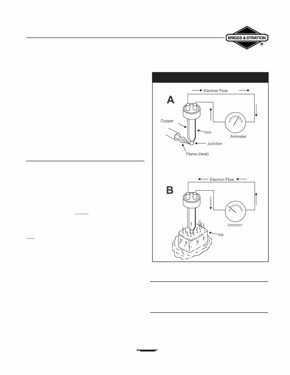
Several basic methods may be used to create an electrical current flow. Four methods will be discussed here.All of these methods are based on a fundamental law that energy can never be created or destroyed but can be changed into other forms of energy.Thus, chemical, heat, light and magnetic energy can be changed into electrical energy. The four basic methods of creating electrical current flow are: • Chemical energy (e.g., storage battery) • Heat energy (e.g., thermocouple) • Light energy (e.g., photo-electric) • Magnetic energy (e.g., alternator or generator) The Thermocouple When two dissimilar metals are welded together and the welded junction is heated or cooled, an electro-motive force (EMF) is produced.The joining process appears to disturb the atomic orbits at the junction, so that the outer electrons in both metals are loosely held.Any small addition or subtraction of heat energy will set these electrons free. Figure 1.5 shows a union between iron and copper wires, this union forms a thermocouple. In Figure 1.5A, the heat of the flame has caused the copper atoms to lose electrons. The copper draws electrons from the iron and a current flow in one direction is produced. In Figure 1.5B, the wire junction has been cooled, causing the ir on atoms to lose electrons and attract electrons from the copper.The resulting current flow is then reversed from that of Figure 1.5A. Photoelectric Cell Copper oxide and selenium oxide are sensitive to rays of light. Materials that create a current flow when exposed to light are said to be “photo-voltaic.” Magnetic Energy Magnetism is closely related to electricity. It can be used to produce electricity and electricity can be used to produce magnetism.A study of one must, therefore, include a study of the other. 5 CREATING CURRENT FLOW Section 1 • Generator Fundamentals Portable Generator Familiarization & Troubleshooting Guide Figure 1.5 — The Thermocouple
Magnetic “lines of force” surround a magnet.These lines of force are concentrated at the magnet’s NORTH and SOUTH poles and are often called “lines of flux” (Figure 1.6). The flux lines are directed a wa y from the magnet at its north pole and r e-enter the magnet at its south pole. Like the positive (+) and negative (-) electrical charges previously discussed, the same magnetic poles repel each other and unlike poles attract each other. When discussing magnetism, two terms should be defined: • Permeability: The ease with which any given substance can be magnetized. • Retentivity: The ability of a substance to retain its magnetism when an external magnetic field is removed (also known as “Residual Magnetism”). Current Flow and Magnetism All conductors through which an electrical current is flowing have a magnetic field surrounding them.The greater the current (electron) flow, the stronger or more concentrated the magnetic field.To determine the direction of magnetic lines of force around a wire, you can use a simple rule called the “Right Hand Rule.” Simply place your right hand around the wire with your thumb pointing in the direction of the current flow (positive to negative).The fingers then point in the direction of the magnetic lines of force (Figure 1.7). When conductor wires are formed into a coil, a north magnetic pole is created in half of the coil and a south magnetic pole is created in the other half. Determine polarity (direction of the lines of force) in the coil by grasping it in the right hand with the fingers pointing in the direction of current flow.The thumb then points to the coil’s north pole. Simple Permanent Magnet Generator When a wire is moved so that it intersects (cuts across) a magnetic field, an electro-motive force (EMF) is induced in that wire (Figure 1.8).This is the principle upon which a rotating armature generator is based. 6 Section 1 • Generator Fundamentals Portable Generator Familiarization & Troubleshooting Guide Figure 1.6 — Lines of Flux Around A Magnet Figure 1.7 — The Right Hand Rule Figure 1.8 — Simple Revolving Armature Generator
Section 1 • Generator Fundamentals Portable Generator Familiarization & Troubleshooting Guide Electromagnetic Induction In 1831, scientists observed that a conductor moving through a magnetic field would have a voltage or electro- motive force (EMF) induced into itself. Electromagnetic induction may be defined as the action of inducing of a voltage into a conductor by moving it through a magnetic field.This principle is illustrated in Figure 1.9. A straight wire conductor is moving through the magnetic field of a horseshoe magnet. If a sensitive voltmeter were attached to the ends of the wire conductor, a small voltage would be indicated as the wire moved through the magnetic field. However, if the wire conductor were moved parallel to the lines of magnetic force, no voltage would be indicated. The greater the strength of the magnetic field through which the wire conductor is moved, the greater the induced voltage in the conductor. Another familiar form of electromagnetic induction is the automotive engine ignition coil. Current flow through a primary coil of wires creates a magnetic field around that coil, which then cuts through a secondary coil of wires. When the current flow through the primary wire coil is interrupted, by opening a set of breaker points, the collapse of the magnetic field induces an electro-motive force (EMF) in the secondary coil (Figure 1.10) Electromagnetism The previous paragraph explained that magnetic lines of force, cutting through the stationary windings of the stator assembly, would induce an EMF into those windings. Conversely,when a current flows through a wire conductor, a magnetic field is created around that wire.The number of lines of magnetic force, or strength of the magnetic field, increases as the current is increased through the conductor. When a current-carrying wire is wound into a number of loops, to form a coil, the magnetic field created is the sum of all single-loop magnetic fields added together.With lines of magnetic force entering the coil at one end and leaving at the other end, a north and south pole are formed at the coil ends, as in a bar magnet (Figure 1.11). 7 Figure 1.9 — Electromagnetic Induction Figure 1.10 — Typical Automotive Ignition System Figure 1.11 — Magnetic Field Around A Coil Of Wire
If the coil is wound around a core of magnetic material, such as iron, the strength of the magnetic field at the north and south poles is greatly increased (Figure 1.12). This happens because air is a poor conductor of magnetic lines and iron is a very good conductor. Using iron in a magnetic path may increase the magnetic strength of a coil by 2500 times over that of air. The strength of the magnetic poles in a coil of wire is directly proportional to: The number of turns of wire. The current (in amperes) flowing through the wire. A coil carring a current of one ampere through 1000 turns of wire and another coil carring 10 amperes through 100 coils of wire will each create a magnetic field strength 1000 ampere-turns (Figure 1.13). The term “ampere-turns” is the measure of the strength of a magnetic field. Direct Current (DC) The current flow created by a storage battery flows through a conductor in one direction only.This type of current flow is called direct current or (DC). Alternating Current (AC) Alternating current or (AC) is the flow of electrons through a conductor first in one direction and then in the other.This can be explained by showing the operation of a simple alternating current (AC) generator (Figure 1.14). 8 Section 1 • Generator Fundamentals Portable Generator Familiarization & Troubleshooting Guide Figure 1.12 — Iron Core Increases Strength of Field Figure 1.13 — Example of “Ampere-Turns” Figure 1.14 — An Aternating Current Generator
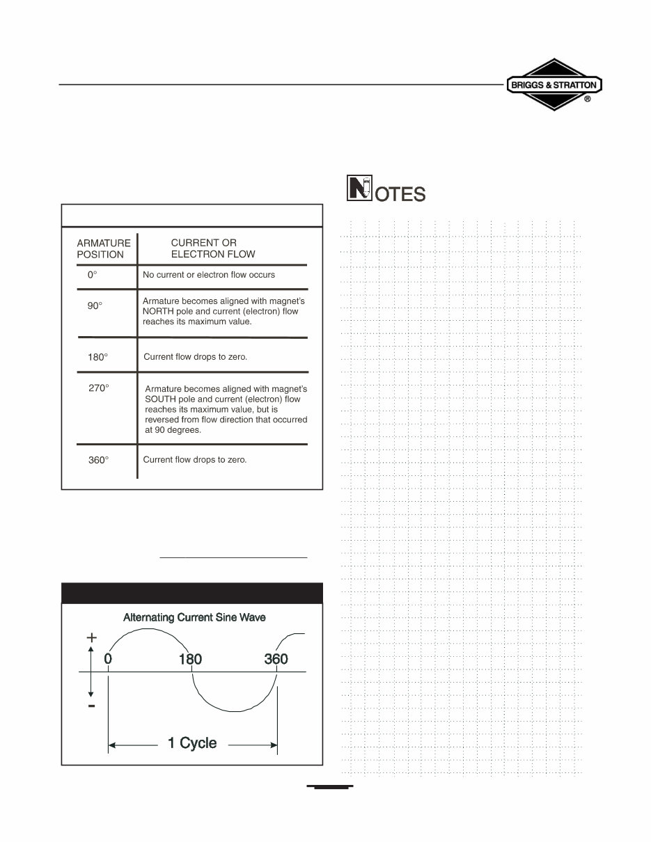
Section 1 • Generator Fundamentals Portable Generator Familiarization & Troubleshooting Guide The flow of electrons changes direction according to the rotating armature's position in relation to the poles of a magnetic field (See the Table 1.1). A wave diagram (sine wave) of alternating current shows that current goes from a zero value to maximum positive value (0°- 90° degrees), and then returns to zero (Figure 1.15).Two such current reversals (1 positive and 1 negative) are called “one cycle.” The n umber of cycles_per second , is called frequency and is often stated as 'Hertz or “CPS.” 9 Table 1.1 — Current Flow Pattern Figure 1.15 — An Alternating Current Sine Wave
MyGreenManuals.com is your number one source for repair manuals. Our informative repair manuals, owner's manuals, and parts catalogs contain all the information you'll need to perform repairs, look up parts, or do routine maintenance on your machine. You will have access to information regarding the following topics:
General Information
Routine Maintenance
Engine Removal and Installation
Fuel System
Lubrication and Cooling System
Engine Specifications
Transmission, Drive Chain & Sprockets
Steering System
Shocks
Body Work
Intake & Exhaust
Electrical System
Advanced Troubleshooting
And much more!
With our repair manuals, find the page pertaining to your job, print it off, and get working on your machine. No more ruining your expensive paper shop manual with grease and dirt.
Broke down on the trail or site and have a smartphone? What a cool way to find your problem and repair it on the trail, no downtime on the job site. With our repair manuals, you instantly have access to the material needed to get you running again. Kind of tough to do that with a paper manual.
And did we mention the fact that you're saving the trees? All our repair manuals come with a lifetime protection policy. If lost or damaged, simply contact us, and we'll replace it free of charge for life.
We provide various repair service manuals, workshop manuals, repair manuals, owner's manuals, parts catalogs, and other various manuals for UTVs, motorcycles, ATVs, quads, snowmobiles, Seadoo, equipment, small engines, inboards, outboards, and more, all in an electronic format.
Instant Access
No Shipping Cost
Get a Copy So No Waiting, Repair It Now
If you are looking for a specific manual and cannot find it or do not see it listed, then contact our customer support team via the contact us link above with details of the required manual, and we will do our absolute best to find and list it for you.
Instant access after payment. Thank you.
Recently Viewed
5,521,897Happy Clients
2,594,462eManuals
1,120,453Trusted Sellers
15Years in Business
Price:
Actual Price:
Briggs and Stratton Generac Portable Generator Repair Manual