

Briggs & Stratton Generator 5500 8500 Complete Workshop Service Repair Manual
What's Included?
Fast Download Speeds
Online & Offline Access
Access PDF Contents & Bookmarks
Full Search Facility
Print one or all pages of your manual
Familiarization & Troubleshooting Guide
GENERATOR

FORWARD
This guide has been written and published by Briggs & Stratton Corporation to aid our
dealers’ mechanics and company service personnel when servicing the products described
herein.
It is assumed that these personnel are familiar with the servicing procedures for these
products, or like or similar products, manufactured by Briggs & Stratton Power Products. It is
also assumed that they have been trained in the recommended servicing procedures for these
products, which includes the use of mechanics hand tools and any special tools that might be
required.
Proper service and repair is important to the safe, economical and reliable operation of all
engine driven systems. The troubleshooting, testing, service and repair procedures described
in this guide are effective methods of performing such operations.
We could not possibly know of and advise the service trade of all conceivable procedures or
methods by which a service might be performed, nor of any possible hazards and/or results
of each procedure or method. We have not undertaken any such wide evaluation. Therefore,
anyone who uses a procedure or method not described by the manufacturer must first satisfy
himself that neither his safety, nor the safety of the product, will be endangered by the
service or operating procedure selected.
All information, illustrations, and specifications contained in this guide are based on the latest
production information available at the time of publication. However, Briggs & Stratton
Corporation reserves the right to change, alter, or otherwise improve the product at any time
without prior notice.
Some components or assemblies of the product described in this guide may not be considered
repairable. Disassembly, repair and reassembly of such components may not be included in
this guide.
Service and repair instructions for the engines used to power these products are not covered
in this guide. Engine service and repair instructions are furnished by the engine manufacturer.
Copyright © 2006 Briggs & Stratton Corporation
All rights reserved.
No part of this material may be reproduced or transmitted, in any form or by any means,
electronic or mechanical, including photocopying, recording or by any information storage
and retrieval system, without prior permission in writing from Briggs & Stratton Corporation.
Generator
Fundamentals
Basic Electricity 3
Magnetism and Electricity 3
Electro-Motive Force 4
Electromagnetism 7
Direct Current (DC) 8
Alternating Current (AC) 8
Volt 10
Ampere 10
Ohm 10
Ohm’s Law 11
The Watt 11
Electrical Formulas 12
The Series Circuit 13
The Parallel Circuit 13
The Series-Parallel Circuit 14
Simple Alternator 17
Simple Alternator Operation 17
Generator Components
And Systems
Generator Components 19
Rotor Assembly 20
Stator Assembly 21
Switches 23
Fuses 26
Circuit Breakers 26
Solenoids 27
Relays 28
Resistors 29
Transformers 31
Condensers 32
Rectifiers 33
Transistors 34
Brushes and Brush Holders 35
Voltage Regulator 37
Generator Systems 41
Revolving Field Excitation Methods 42
Direct Excitation 42
The Brushless Excitation Method 44
Field Boost Assembly 45
Power Factor 46
Oil Pressure Switch On “GN” Engines 49
Typical Automatic Idle Control System 50
Early V-Twin Engine Idle Control 51
Idle Control on “GN”
190, 220, 320, 360, & 410 ENGINES 51
“XL” And “MC” Idle Control On
480 & 570 V-Twin Engines 53
1
GENERAC
®
PORTABLE PRODUCTS
Table of Contents
Portable Generator Familiarization & Troubleshooting Guide
Generator Diagnostics And
Adjustments
Troubleshooting Idle Controls 56
Troubleshooting Flowchart For
“Direct Excited” (Brush Type)
Generators 68
Troubleshooting Flowchart For
(Brush Type) Generators With
“Two Board” Regulation 76
Troubleshooting Flowchart For
“Sincro® Wound” (Brushless Type)
Generators 84
Voltage Regulator Adjustments 90
Generator Assemblies
Generac® Wound Generators 94
Disassembly 94
Assembly 101
Sincro® Wound Generators 109
Disassembly 109
Assembly 112
Appendix A
Generac® Torque Table 117
Generac® Receptacles And Plugs 118
Glossary 120
2
GENERAC
®
PORTABLE PRODUCTS
Table of Contents
Portable Generator Familiarization & Troubleshooting Guide
BASIC ELECTRICITY
Section 1 • Generator Fundamentals
Portable Generator Familiarization & Troubleshooting Guide
3
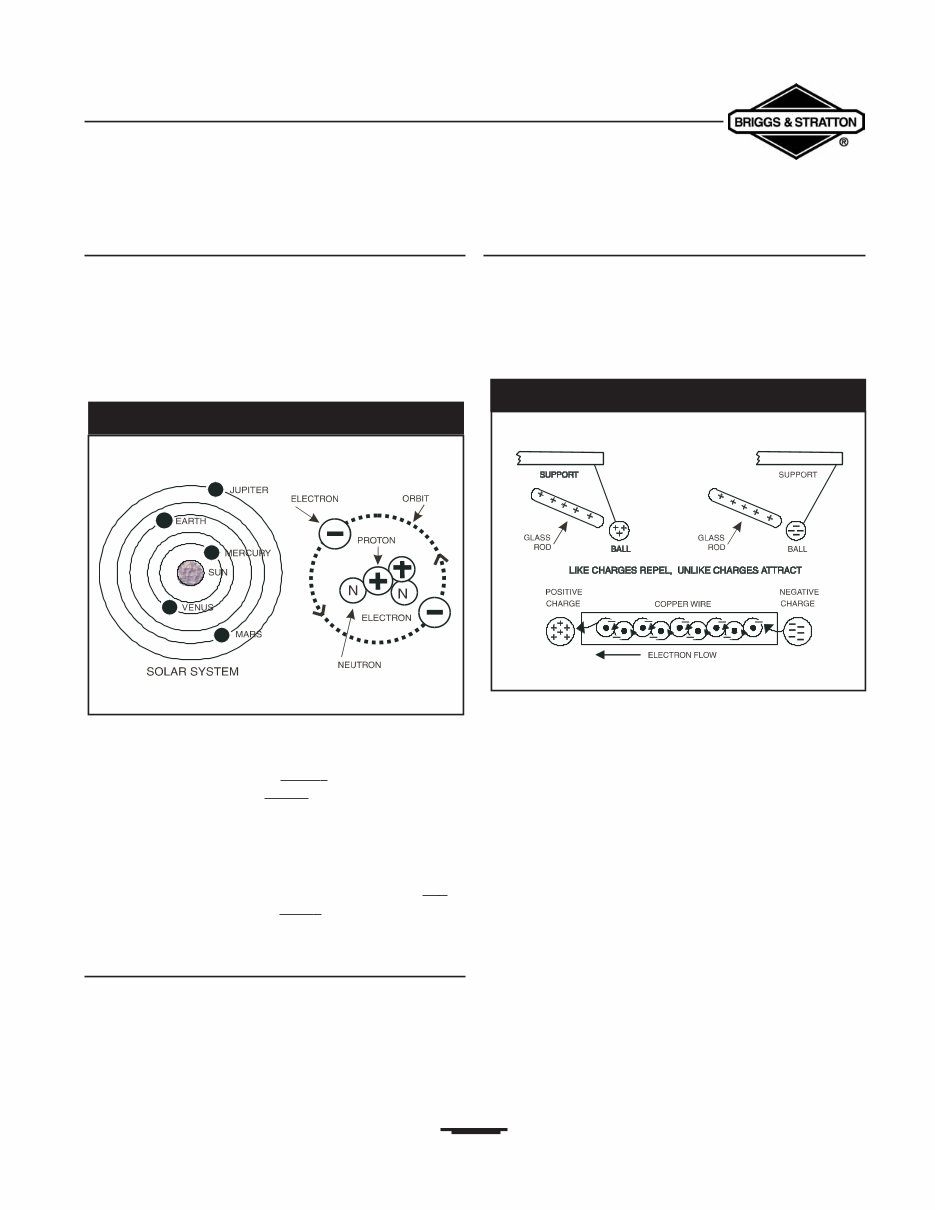
The Atom
All matter is made up of atoms.An atom may be compared
to a solar system that has several planets revolving around
the sun.There are more than 100 different kinds of atoms.
The various atoms combined together form all known
substances.
The structure of the helium atom is shown in
Figure 1.1.
Negatively (-) charged particles called electrons revolve
around a positively charged nucleus.The nucleus is made up
of both protons, which have a positiv e (+) electrical charge,
and neutrons, which have a neutral (N) electrical charge.
The negative and positive particles that make up an atom act
much like the north and south poles of a magnet, in which
the north pole is positive (+) and the south pole is
negative (-).
Every child who has played with a magnet knows that lik e
poles repel each other and unlik e poles attract each
other.
Magnetism and Electricity
Like the poles of a magnet, atomic particles with the same
charges repel each other and the particles with different
charges attract each other. In a normal atom, the positive
charge of the nucleus exactly balances the negative charge of
the electrons that rotate around it.
Borrowing Of Electrons
If an atom loses electrons, the positive (+) charge of the
nucleus and the negative (-) charge of the electrons
revolving around it is no longer balanced.The atom then
becomes positively charged.The natural tendency of the
positively charged atom is to attract any other negative
charges, such as an electron from another atom (Figure 1.2).
The positively charged atom attempts to return to a
balanced (or neutral) state and will “borrow” an electron
from a neighboring atom.When an atom borrows an
electron from its neighbor, the neighbor then becomes
positively charged.This starts a “chain reaction” in which
each atom in turn borrows an electron from its neighboring
atom.
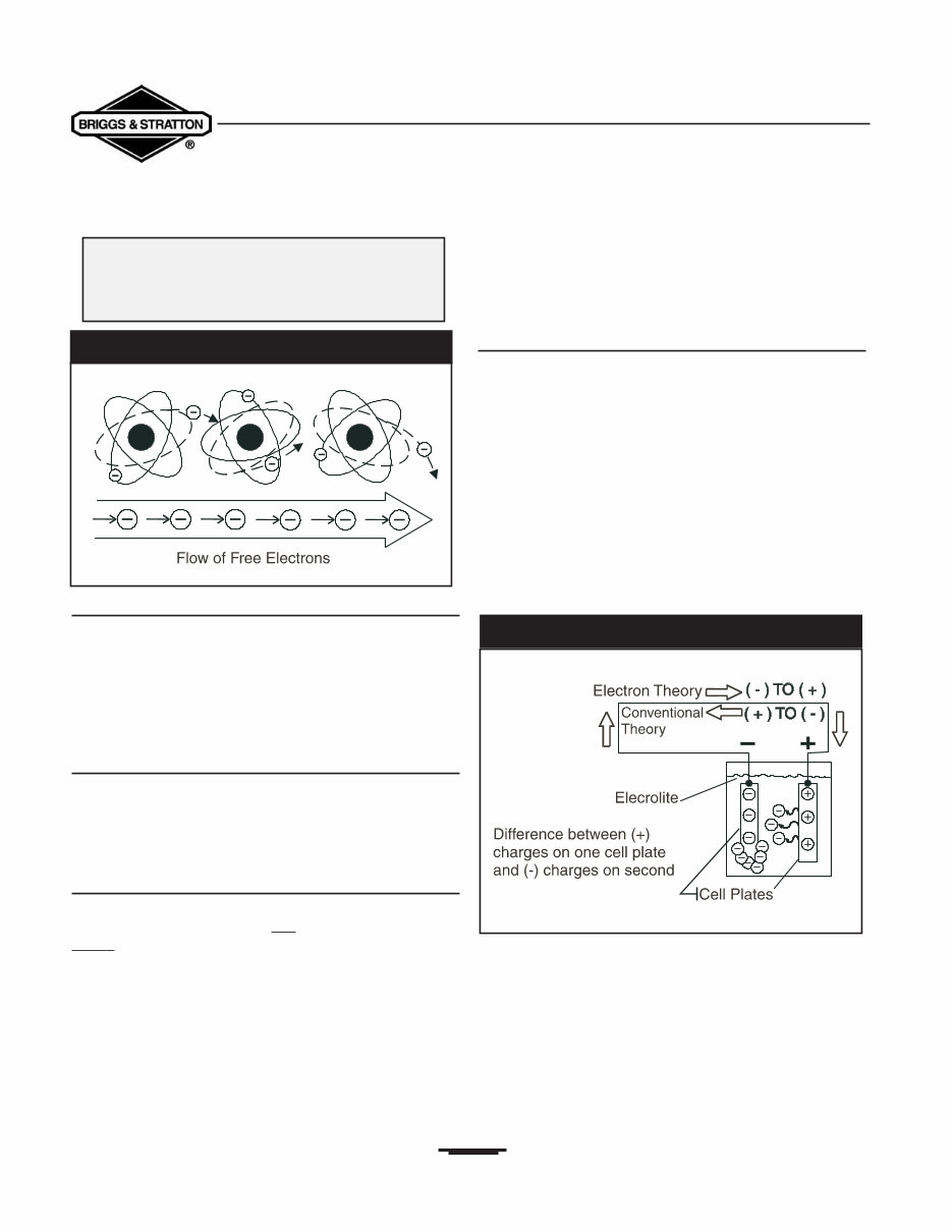
This borrowing of electrons creates a flow of current
that continues until all the atoms have achieved a
state of balance.
Figure 1.3 illustrates the transfer of electrons from one atom
to the next and the resulting flow of free electrons that
occurs.This may be difficult to visualize, unless you
remember that an electron is so small that it finds great
empty spaces for free travel, even in a solid substance.
Figure 1.1 — The Helium Atom
Figure 1.2 — Magnetism and Electricity
Section 1 • Generator Fundamentals
Portable Generator Familiarization & Troubleshooting Guide
Conductors and Non-Conductors
Some materials (such as copper or silver) will readily
transfer electrons from atom to atom.These materials are
called conductors. Other materials hold their electrons
very tightly and are said to have “bound” electrons.These
non-conductors, materials such as wood, glass or rubber,
are often used as insulators.
Current Flow Versus Electricity
Electricity is created by the action of electrons in motion.
Current flow is the flow of free electrons through a
conductive path (circuit).Thus, electricity is a form of energy
while current flow is the harnessing of that energy.
Two Theories of Current Flow
The Electron Theory: As previously discussed, current
flow is based on the fact that: “lik e charges repel and
unlik e charges attract.” An electron, a negatively (-)
charged particle, is attracted to a proton, a positively(+)
charged particle.The Electron Theory of Electricity states
that electron or current flow in a circuit goes from the
negative side of that circuit to the positive side.
The Conventional Theory: This theory states that
current or electron flow in a circuit goes from the positive
side of that circuit to its negative side.
The difference between conventional and electron theories
is mentioned because the conventional theory is more
commonly used in everyday applications. For this guide,
however, we will use the Electron Theory.
Electro-Motive Force
Current flow occurs in a conductor only when there is a
difference in electrical “potential” and when there is a
complete path or circuit for electron flow.The force that
causes the electrons to flow is called:
“Electro-Motive Force” or ”EMF.” This force is equal
to the difference in electrical potential across the circuit.
To illustrate the difference in potential,consider a storage
battery as a model.This type of battery consists of two
metal plates of different elements immersed in a fluid.A
chemical reaction causes an electrical charge to be created
on each of the metal plates.The fluid (called “electrolyte”)
carries electrons away from one plate and deposits them on
the other plate (Figure 1.4).
The plate that has gained electrons has become negatively
charged.This creates a difference in electrical potential
between the two metal plates. If a conductor is now
connected across the two metal plates, a circuit is completed
and the result is a flow of electrons to the positively charged
plate.
As long as there is a difference in electrical potential
between the two plates (positive versus negative
charge), current continues to flow.
4
Electrical current flow is based on the
principle:
That atoms have the ability to readily
transfer and borrow electrons
Figure 1.3 — Transfer of Electrons
Figure 1.4 — Electron Flow
Several basic methods may be used to create an electrical
current flow. Four methods will be discussed here.All of
these methods are based on a fundamental law that energy
can never be created or destroyed but can be changed into
other forms of energy.Thus, chemical, heat, light and
magnetic energy can be changed into electrical energy.
The four basic methods of creating electrical current flow
are:
• Chemical energy (e.g., storage battery)
• Heat energy (e.g., thermocouple)
• Light energy (e.g., photo-electric)
• Magnetic energy (e.g., alternator or generator)
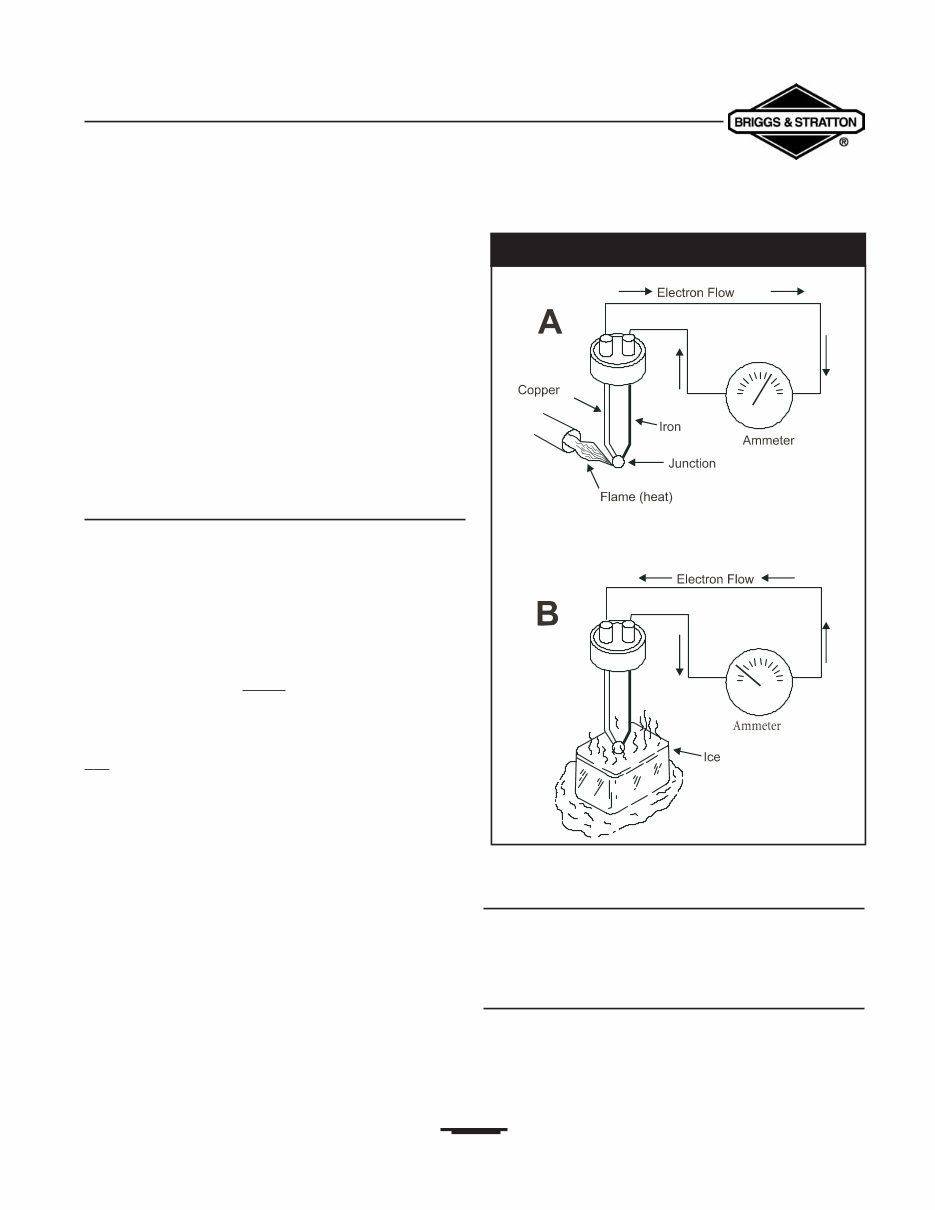
The Thermocouple
When two dissimilar metals are welded together and the
welded junction is heated or cooled, an electro-motive force
(EMF) is produced.The joining process appears to disturb
the atomic orbits at the junction, so that the outer electrons
in both metals are loosely held.Any small addition or
subtraction of heat energy will set these electrons free.
Figure 1.5 shows a union between iron and copper wires,
this union forms a thermocouple. In Figure 1.5A, the heat of
the flame has caused the copper atoms to lose electrons.
The copper draws electrons from the iron and a current
flow in one direction is produced.
In Figure 1.5B, the wire junction has been cooled, causing the
ir on atoms to lose electrons and attract electrons from the
copper.The resulting current flow is then reversed from that
of Figure 1.5A.
Photoelectric Cell
Copper oxide and selenium oxide are sensitive to rays of
light. Materials that create a current flow when exposed to
light are said to be “photo-voltaic.”
Magnetic Energy
Magnetism is closely related to electricity. It can be used to
produce electricity and electricity can be used to produce
magnetism.A study of one must, therefore, include a study of
the other.
5
CREATING CURRENT FLOW
Section 1 • Generator Fundamentals
Portable Generator Familiarization & Troubleshooting Guide
Figure 1.5 — The Thermocouple
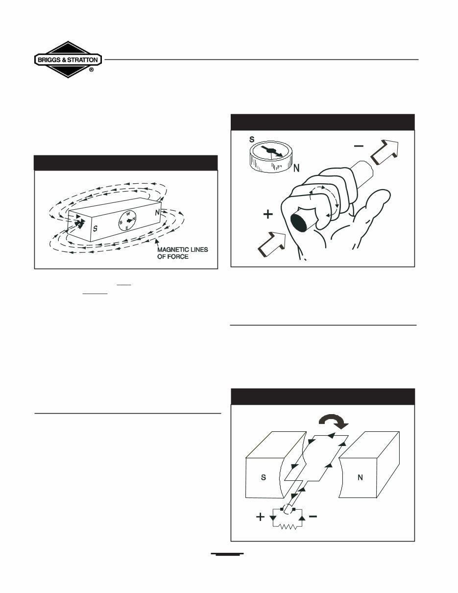
Magnetic “lines of force” surround a magnet.These lines of
force are concentrated at the magnet’s NORTH and SOUTH
poles and are often called “lines of flux”
(Figure 1.6).
The flux lines are directed a wa y from the magnet at its
north pole and r e-enter the magnet at its south pole. Like
the positive (+) and negative (-) electrical charges previously
discussed, the same magnetic poles repel each other and
unlike poles attract each other.
When discussing magnetism, two terms should be defined:
• Permeability: The ease with which any given
substance can be magnetized.
• Retentivity: The ability of a substance to retain its
magnetism when an external magnetic
field is removed (also known as “Residual
Magnetism”).
Current Flow and Magnetism
All conductors through which an electrical current is flowing
have a magnetic field surrounding them.The greater the
current (electron) flow, the stronger or more concentrated
the magnetic field.To determine the direction of magnetic
lines of force around a wire, you can use a simple rule called
the “Right Hand Rule.” Simply place your right hand
around the wire with your thumb pointing in the direction
of the current flow (positive to negative).The fingers then
point in the direction of the magnetic lines of force
(Figure 1.7).
When conductor wires are formed into a coil, a north
magnetic pole is created in half of the coil and a south
magnetic pole is created in the other half.
Determine polarity (direction of the lines of force) in the
coil by grasping it in the right hand with the fingers pointing
in the direction of current flow.The thumb then points to
the coil’s north pole.
Simple Permanent Magnet Generator
When a wire is moved so that it intersects (cuts across) a
magnetic field, an electro-motive force (EMF) is induced in
that wire (Figure 1.8).This is the principle upon which a
rotating armature generator is based.
6
Section 1 • Generator Fundamentals
Portable Generator Familiarization & Troubleshooting Guide
Figure 1.6 — Lines of Flux Around A Magnet
Figure 1.7 — The Right Hand Rule
Figure 1.8 — Simple Revolving Armature Generator
Section 1 • Generator Fundamentals
Portable Generator Familiarization & Troubleshooting Guide
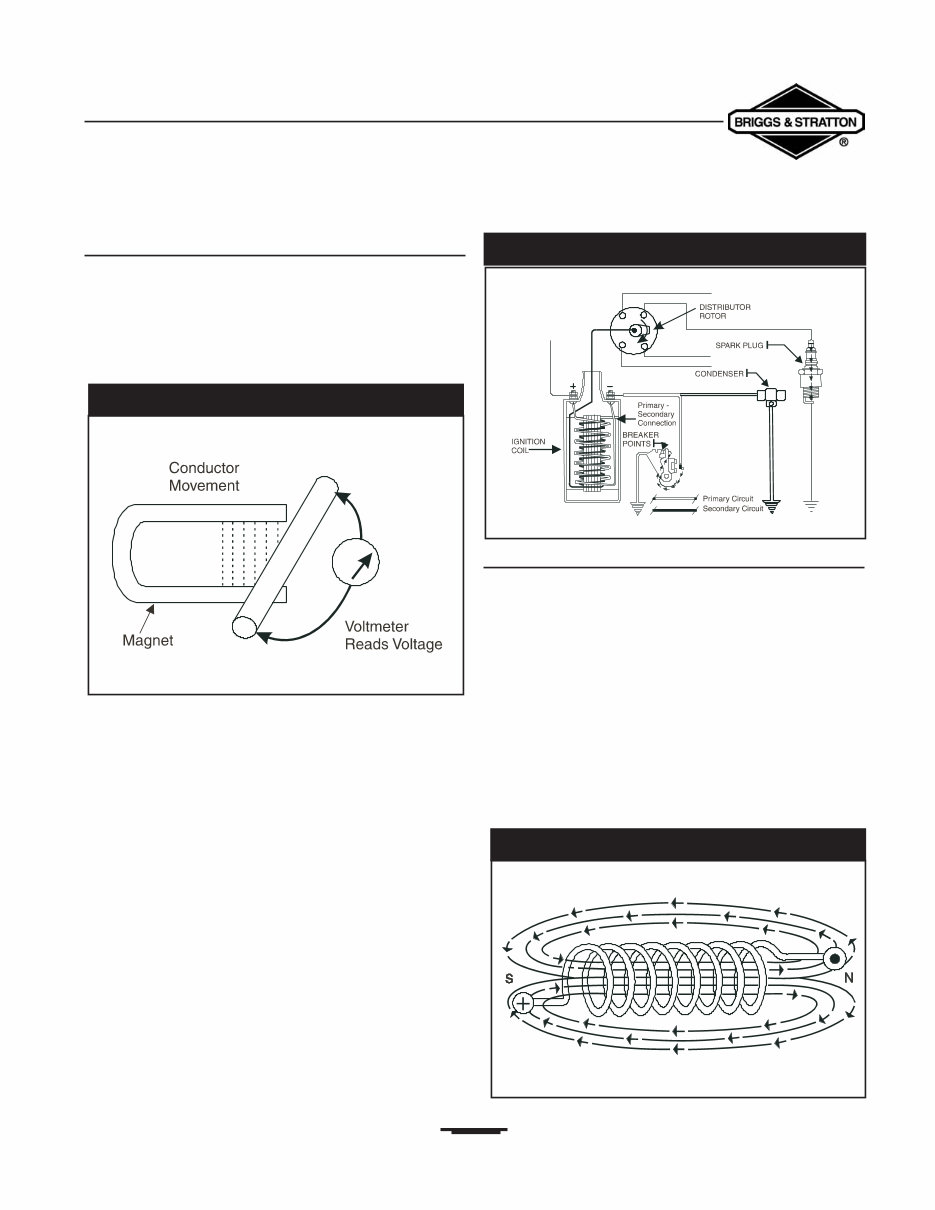
Electromagnetic Induction
In 1831, scientists observed that a conductor moving
through a magnetic field would have a voltage or electro-
motive force (EMF) induced into itself. Electromagnetic
induction may be defined as the action of inducing of a
voltage into a conductor by moving it through a magnetic
field.This principle is illustrated in Figure 1.9.
A straight wire conductor is moving through the magnetic
field of a horseshoe magnet. If a sensitive voltmeter were
attached to the ends of the wire conductor, a small voltage
would be indicated as the wire moved through the magnetic
field. However, if the wire conductor were moved parallel to
the lines of magnetic force, no voltage would be indicated.
The greater the strength of the magnetic field through which
the wire conductor is moved, the greater the induced
voltage in the conductor.
Another familiar form of electromagnetic induction is the
automotive engine ignition coil. Current flow through a
primary coil of wires creates a magnetic field around that
coil, which then cuts through a secondary coil of wires.
When the current flow through the primary wire coil is
interrupted, by opening a set of breaker points, the collapse
of the magnetic field induces an electro-motive force (EMF)
in the secondary coil (Figure 1.10)
Electromagnetism
The previous paragraph explained that magnetic lines of
force, cutting through the stationary windings of the stator
assembly, would induce an EMF into those windings.
Conversely,when a current flows through a wire conductor,
a magnetic field is created around that wire.The number of
lines of magnetic force, or strength of the magnetic field,
increases as the current is increased through the conductor.
When a current-carrying wire is wound into a number of
loops, to form a coil, the magnetic field created is the sum of
all single-loop magnetic fields added together.With lines of
magnetic force entering the coil at one end and leaving at
the other end, a north and south pole are formed at the coil
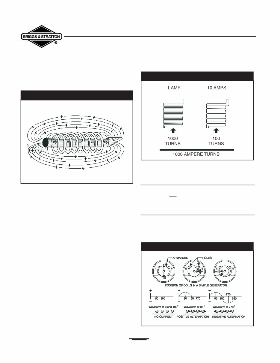
ends, as in a bar magnet (Figure 1.11).
7
Figure 1.9 — Electromagnetic Induction
Figure 1.10 — Typical Automotive Ignition System
Figure 1.11 — Magnetic Field Around A Coil Of Wire
If the coil is wound around a core of magnetic material, such
as iron, the strength of the magnetic field at the north and
south poles is greatly increased (Figure 1.12).
This happens because air is a poor conductor of magnetic
lines and iron is a very good conductor. Using iron in a
magnetic path may increase the magnetic strength of a coil
by 2500 times over that of air.
The strength of the magnetic poles in a coil of wire is
directly proportional to:
The number of turns of wire.
The current (in amperes) flowing through the wire.
A coil carring a current of one ampere through 1000 turns
of wire and another coil carring 10 amperes through 100
coils of wire will each create a magnetic field strength 1000
ampere-turns (Figure 1.13).
The term “ampere-turns” is the measure of the strength
of a magnetic field.
Direct Current (DC)
The current flow created by a storage battery flows through
a conductor in one direction only.This type of current flow
is called direct current or (DC).
Alternating Current (AC)
Alternating current or (AC) is the flow of electrons
through a conductor first in one direction and then in the
other.This can be explained by showing the operation of a
simple alternating current (AC) generator (Figure 1.14).
8
Section 1 • Generator Fundamentals
Portable Generator Familiarization & Troubleshooting Guide
Figure 1.12 — Iron Core Increases Strength of Field
Figure 1.13 — Example of “Ampere-Turns”
Figure 1.14 — An Aternating Current Generator
You're Reading a Preview
What's Included?
Fast Download Speeds
Online & Offline Access
Access PDF Contents & Bookmarks
Full Search Facility
Print one or all pages of your manual
$41.99
Viewed 72 Times Today


Secure transaction
What's Included?
Fast Download Speeds
Online & Offline Access
Access PDF Contents & Bookmarks
Full Search Facility
Print one or all pages of your manual
$41.99
Thank you for considering this comprehensive Service Repair Workshop Manual for the Briggs & Stratton Generator 5500 8500.
This manual is an invaluable resource covering every service and repair procedure necessary, enabling you to save a significant amount of money by performing your own repairs. It provides easy-to-follow, step-by-step instructions accompanied by detailed pictures for all servicing and repairs.
Upon obtaining this manual, it becomes a permanent asset. You have the flexibility to print individual pages, chapters, or the entire manual. Additionally, you can conveniently access it on your tablet or smartphone.
Models Covered:
- All Models/Engines/Trim/Transmissions Types Are Covered
Contents:
- This high-quality Service Repair Workshop Manual encompasses all repair procedures from A to Z.
- Every repair and service procedure is comprehensively addressed.
Computer Requirements:
- This downloadable Manual is compatible with all PC & MAC Computers, tablets, and mobile phones.
- The only software required is Adobe Reader, which is typically pre-installed on your computer. If not, it can be downloaded for free.
Delivery:
- Upon payment via Visa, MasterCard, or PayPal, the manual will be instantly emailed to the address provided during checkout.
Customer Satisfaction Guaranteed.


