2 TS 500i Contents 11. Fuel system 94 11.1 Air filter 94 11.2 Throttle shutter housing / Intake manifold 94 11.2.1 Air baffle / throttle cable 95 11.3 Injection valve 96 11.4 Sensor 99 11.5 Impulse hose 101 11.6 Leak testing 102 11.6.1 Checking the fuel tank / fuel system 102 11.6.2 Checking the tank vent 103 11.6.3 Tank vent Removal and installation 104 11.7 Injection pump 104 11.7.1 Manual fuel pump 104 11.7.2 Injection pump 105 11.8 Fuel intake 106 11.8.1 Pickup body 106 11.8.2 Fuel hoses 106 11.8.3 Fuel tank filler cap 107 11.9 Tank housing 107 12. Special tools 111 13. Service accessories 114
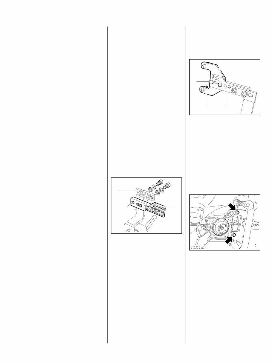
3 TS 500i 1. Introduction and safety precautions 1.1 Introduction This Service Manual contains detailed descriptions of all the typical repair and servicing procedures for this power tool. Refer to the illustrated spare parts lists during all repair work. These lists show the installation position and order in which the individual parts and modules should be assembled. Refer to the latest edition of the relevant spare parts list to check the part numbers of any spare parts required. A fault on the machine may be due to several causes. To help locate the fault, consult the chapter on "Troubleshooting" and the "STIHL Service Training System" for all functional groups. Refer to the "Technical Information" bulletins for engineering changes which have been introduced since publication of this Service Manual. The "Technical information bulletins" also supplement the spare parts list and Service Manual until an updated edition is issued. The special tools mentioned in the descriptions are listed in the chapter "Special Servicing Tools" of this manual. The tools can be identified according to part number in the "Special Tools Manual". The manual lists all tools supplied by STIHL. Symbols are included in the text and pictures for greater clarity. The meanings are as follows: In the text: : = Action to be taken as shown in the illustration above the text – = Action to be taken but not shown in the illustration above the text In the illustrations: A Item pointer (short) aDirection of movement (long arrow) b 4.2 = Reference to another chapter, in this case to Chapter 4.2 Service Manuals and "Technical information bulletins" are intended exclusively for the use of properly equipped repair shops. They must not be passed on to third parties. Servicing and repairs are made considerably easier if the machine is mounted on assembly stand (3) 5910 890 3100. For this purpose, secure the mount (2) 5910 850 1650 to the assembly stand with two screws (1). For the assembly block 5910 890 3101 the abovementioned mounting step is dropped since the mount is already attached. 1 2 3 219RA000 TG The screws must not protrude, as they may damage the housings when clamping the machine, depending on the model. The clamping plate (1) 4238 890 2100 is secured to the mount (2) using two screws M8x20 (3) and washers. Preparing to make repairs In order to be able to clamp the machine for the repair work on the assembly stand, the "cast arm with guard" must be removed b 4.2. The machine is guided by the two front studs on the crankcase through the bushings of the clamping plate and is secured with the nuts (arrows). 3 1 2 3 370RA000 TG 370RA001 TG
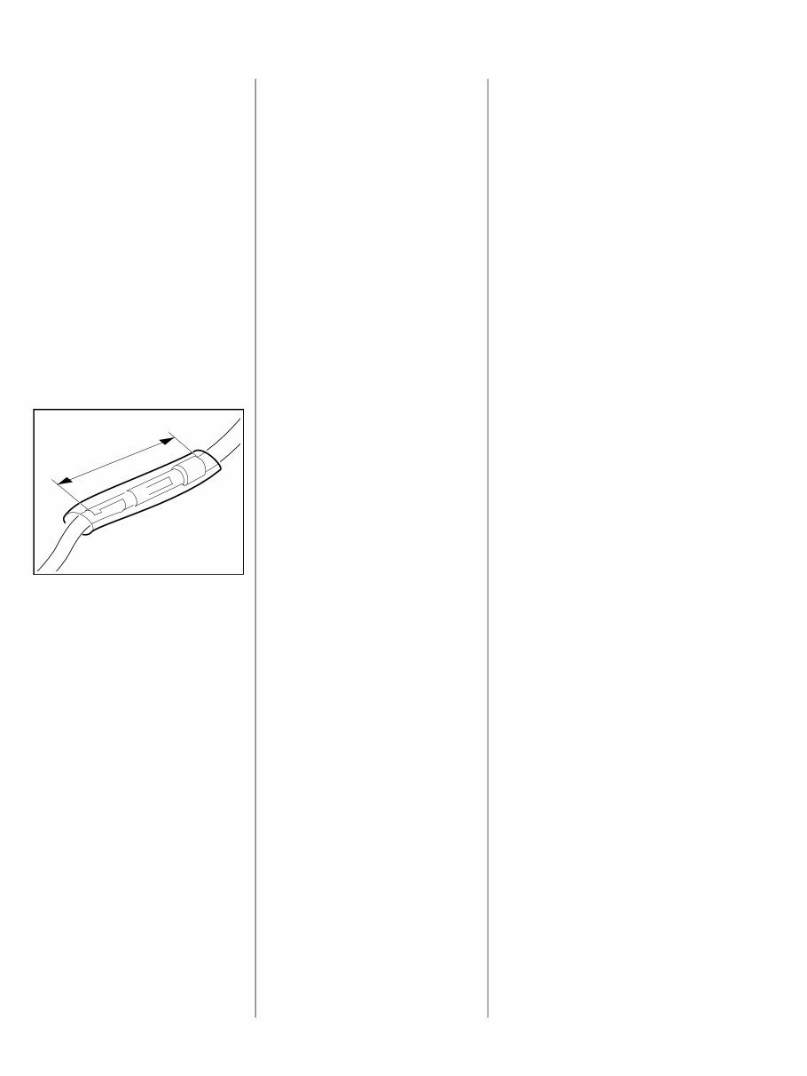
4 TS 500i Always use original STIHL replacement parts. They can be identified by the STIHL part number, the logo STIH) and the STIHL parts symbol ( The symbol may appear alone on small parts. Storage or disposal of fuel Collect fuel in a clean container and dispose of it in accordance with environmental regulations. Plug connections on electrical leads The insulating tube must be oriented so that it is centered over the plug connection and completely enclose the plug connection – danger of short-circuiting. The plug connection is completely plugged together when it has a total length of a = max. 30 mm. Routing the leads In principle, press all electrical leads into the guides using the wiring tool 5910 890 4000. 5902RA299 TG a 1.2 Safety precautions Specific national safety regulations and the safety instructions in the instruction manual must be observed if the machine has to be started up during maintenance or repair work. Fuel is highly inflammable and can also be explosive under certain conditions. Do not bring any fire, flame, spark or other source of heat near the fuel. All work with fuel must be performed outdoors only. Spilled fuel must be wiped away immediately. Test for leakage after all work on the fuel system and engine. Exercise extreme caution while carrying out maintenance and repair work on the electronically controlled injection system – STIHL Injection. The high voltages which occur can cause serious or fatal accidents. Keep everything clean when working on the electronically controlled injection system STIHL Injection. Suitable gloves must be worn without fail if parts are heated for assembly/disassembly purposes. Improper handling may result in burns and other serious injuries. Always replace damaged parts. Check dismantled parts for wear and damage before installation, replace if necessary. Only use the machine with the fan cover mounted – otherwise the rotating flywheel poses a risk of injury and there is a risk of engine damage due to overheating. Only start engine with built-in throttle shutter housing. The chapter "Tightening Torques" lists all components of this machine that must be tightened with the specified tightening torques or coated with thread-locking adhesive. These specifications must be observed throughout the Service Manual when tightening screws and nuts as well as other fasteners.
5 TS 500i Fuel system – barbed connectors Pull or push the fuel hoses, by hand whenever possible, in the direction of the connector in order to ensure leakproofness of the fuel system. Avoid damaging the barbed connectors – sharp-edged pliers, screwdrivers, etc., may not be used. Also, do not cut open fuel hoses with a knife or similar aids. Do not reuse fuel hoses after disassembly, but instead always replace them with new hoses – fuel hoses can be overstretched when being detached. Mount new fuel hoses dry or using STIHL press fluid – apply press fluid to the ends of the hose and the connectors, b 13. Other press fluids are not permitted and may lead to fuel hose damage.
6 TS 500i 2. Specifications 2.1 Engine STIHL Injection Control unit with load dependent, characteristic-curve-driven ignition timing adjustment and fuel injection. Electronic water control The electronic water control makes it possible to feed the optimum amount of water to the abrasive wheel. No water is fed to the abrasive wheel during idling. TS 500i Displacement: 72.2 cm 3 Cylinder bore: 52 mm Stroke: 34 mm Engine power to ISO 7293: 3.9 kW (5.3 HP) at 9500 rpm Cut-off speed: 9800 rpm Max. spindle speed to ISO 19432: 4780 rpm Idle speed: 2500 rpm Clutch: Centrifugal clutch without linings Clutch engages at: 4000 rpm Crankcase leakage test at gauge pressure: p ü = 0.5 bar under vacuum p u = 0.5 bar 2.2 Fuel system Fuel system leakage test at gauge pressure: p ü = 0.8 bar Operation of tank vent at gauge pressure: p ü = 0.3 bar Fuel: as specified in instruction manual 2.3 Spark plug Spark plug (suppressed): Bosch WSR6F NGK BPMR 7 A Electrode gap: 0.5 mm 2.4 Abrasive wheels Composite and diamond cutting wheels Diameter 350 mm Cutting depth 125 mm
7 TS 500i 2.5 Tightening torquese P and DG screws are fitted in plastic and light alloy metal parts. These screws form a permanent thread when they are installed for the first time. The material is permanently deformed. Screws can be removed and installed as often as necessary without impairing the strength of the screwed assembly, provided that the specified tightening torque is observed. For this reason it is essential to use a torque wrench. When inserting DG and P screws into an existing screw thread: Insert the DG or P screw in the hole and turn counterclockwise until it gently drops into the hole in axial direction and engages the existing threads. Tighten the screw clockwise to the specified torque. This procedure ensures that the screw engages properly in the existing thread and does not form a new thread and weaken the assembly. For the microencapsulated screw, before renewed assembly, clean both threads (insert tap in the internal thread by hand and then blow out the threaded hole, brush off the exterior thread), coat the cleaned screw with medium-strength Loctite 242 or 243. Screwdriver speed when used in plastic material: P and DG screws max. 500 rpm. Do not use an impact wrench to release or tighten screw connections. Screws with and without locking serration must not be confused. Fastener Thread size For component Tightening torques Comment Nm Screw P4x16 Limit stop / cast arm 1.8 Screw M8 Stop pin / cast arm 5.0 Screw M6x28 Cast arm / flange 8.0 2) Collar nut M8 Cast arm / rewind starter / stud 20.0 Screw M5x17 Cover / shroud (service cover) 4.5 Screw P6x19 Cap / solenoid valve / tank housing 6.0 M10x1 Decompression valve 14.0 Screw M4x20 Injection valve / crankcase 3.0 2) Screw M5x20 Filter cover / tank housing 6.0 Screw M4x9.6 Spark arresting screen / muffler 2.0 Screw M5x20 Generator / crankcase 6.0 2) Screw P5x16 Handle molding / shroud 4.0 Screw D5x20 Rubber buffers / support 6.0 6) Screw P5x16 Holder / switch / shroud 4.0 Screw P6x19 Shroud / tank housing 6.0
8 TS 500i Fastener Thread size For component Tightening torques Comment Nm Screw M5x17 Cap, spark plug cover / shroud 4.5 Nut M10x1 L V-belt pulley, front 45.0 Screw P6x40 Clamp / handlebar / tank housing 6.0 Screw P6x26 Clamp / tank housing 6.0 Screw D5x45 Clamp / antivibration system / handlebar holder 6.0 2) Screw M5x35x22 Manifold / throttle shutter housing / cylinder 6.0 2 Screw P6x19 Crankcase / bearing plug antivibration system 6.0 Screw M5x32x22 Crankcase / cylinder 9.0 2) Screw M5x20 Crankcase clutch side / fan side 8.0 2) Screw M5x35x22 Crankcase clutch side / fan side 8.0 2) Screw P5x16 Bearing plug antivibration system / tank housing 4.0 Screw M5x20 Fan cover / crankcase 6.0 2) Screw P6x19 Air baffle / tank housing 6.0 Screw M5x20 Air guide shroud / crankcase 3.0 2) Screw M4x12 Ground wire / cover / crankcase 4.0 3) M12x1 L Carrier 40.0 Screw P3x6 Rewind spring / starter cover 0.5 Screw M5x20 Muffler / cylinder 1st stage 2.5 2) Screw M5x20 Muffler / cylinder 2nd stage 10.0 2) Screw M5x20 Muffler / crankcase 10.0 2) Screw G 3/8" Hose connection / solenoid valve 2.0 Screw M5x21 Guard / cast arm 6.0 Nut M8x1 Flywheel / crankshaft 33.0 5)
9 TS 500i Fastener Thread size For component Tightening torques Comment Nm Screw M4x12 Sensor / crankcase 2.0 3) Screw M3x20 Hose clamp, manifold / cylinder 0.5 Screw D5x24 Clamping lever / cast arm 4.0 2) Nut M8x1 Starter cup / crankshaft 33.0 Screw M8x53 Stud / crankcase 21.0 4) Screw P6x50 Support / clamp / handlebar / tank housing 6.0 Screw P6x19 Support / bearing plug antivibration system 6.0 Screw P6x40 Support / tank housing 6.0 Screw M10x18 Abrasive wheel 30.0 Screw M5x30 Adjusting lever / guard 6.0 2) Screw M8x24 Adjusting lever / guard / square nut 4.0 Screw M8x17 Adjusting lever / guard / square nut 4.0 M14x1.25 Spark plug 25.0 Screw M4x8 Pan head screw / banjo screw 3.0 1) Loctite 243 medium strength 2) Easy-slide coating with locking serration 3) Microencapsulated with locking serration 4) Microencapsulated 5) Connection between crankshaft and flywheel must be degreased and oil-free 6) Easy-slide coating
The STIHL TS 500i Cut-Off Saw Machine Workshop Service Repair Manual is a comprehensive resource for maintaining and repairing the 72.2 cc engine. It is compatible with all Windows and Mac versions and requires Adobe Acrobat Reader for viewing. The file size is 08 MB.
The manual includes detailed sections covering introduction, safety precautions, specifications, troubleshooting chart, tightening torque, cast arm with guard, water system, testing radial and axial truth of running, ribbed poly V-belt, tensioner system, starter cup, clutch system, belt pulley/clutch drum, engine system, muffler/spark arresting screen, leak testing, oil seals-shroud, cylinder-crankshaft, piston-piston rings, decompression valve, STIHL injection, starter system, rope rotor system, antivibration elements, handlebar system, rubber buffers/support, switch shaft, throttle trigger, trigger interlock, fuel system, air filter system, throttle shutter housing, intake manifold, injection pump, fuel intake system, tank housing system, special tools, and service accessories.
This electronic manual allows for easy printing of specific pages as needed. It contains detailed illustrations, step-by-step written instructions, diagrams, and pictures, making it an invaluable resource for both DIY enthusiasts and experienced mechanics. By using this repair manual, you can effectively and affordably maintain your machine's proper functionality.
Recently Viewed
5,521,897Happy Clients
2,594,462eManuals
1,120,453Trusted Sellers
15Years in Business
Price:
Actual Price:
STIHL TS 500i CUT-OFF SAW MACHINE Workshop Service Manual