


A Product of Hard Work
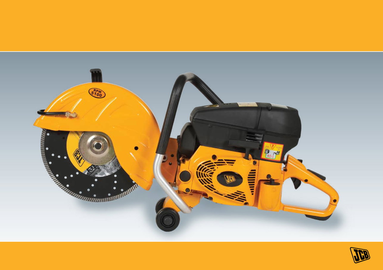
JCB CUT OFF SAW CS-300 & CS-350 SERVICE MANUAL
PETROL CUT-OFF SAW
www.petrolsaw.com

JCB CUT-OFF SAW | CONTENTS
Introduction-How a Two Stroke Engine Works 1
Specifications 1
Troubleshooting, Diagnosis & Remedies
Questions to Ask Customers 3
Look at the Air Filter First 3
Quick Check of Piston and Cylinder 3
Start of in-Depth Testing 3
If the Engine Will Not Start 4
Carburetor 4
Air Leaks 7
Ignition system 7
If there is no spark 7
Lubrication 7
Cooling System 7
Disassembly and Assembly Procedures
Air Filter 8
Starter Cover 8
Filter fix foundation 8
Carburetor 8
Cylinder 8
Piston Rings 9
Piston 9
Muffler 9
Clutch 9
Ignition Module 11
Starter Pawls 11
Flywheel 11
Decompression Valve 12
Crankcase 12
Crankshaft 12
Main Crankshaft Bearing 12
Assembly of Crankcase, Crankshaft and Main Crankshaft Bearing 13
Crankshaft Seals 13
Recoil Assembly 13
Blades 14
Belt cover 14
Cutting Arm 14
Blade Flanges 14
Blade Drive Pulley 14
Blade Shaft or Spindle 15
Blade Shaft Bearings 15
JCB CUT-OFF SAW | SPECIFICATIONS
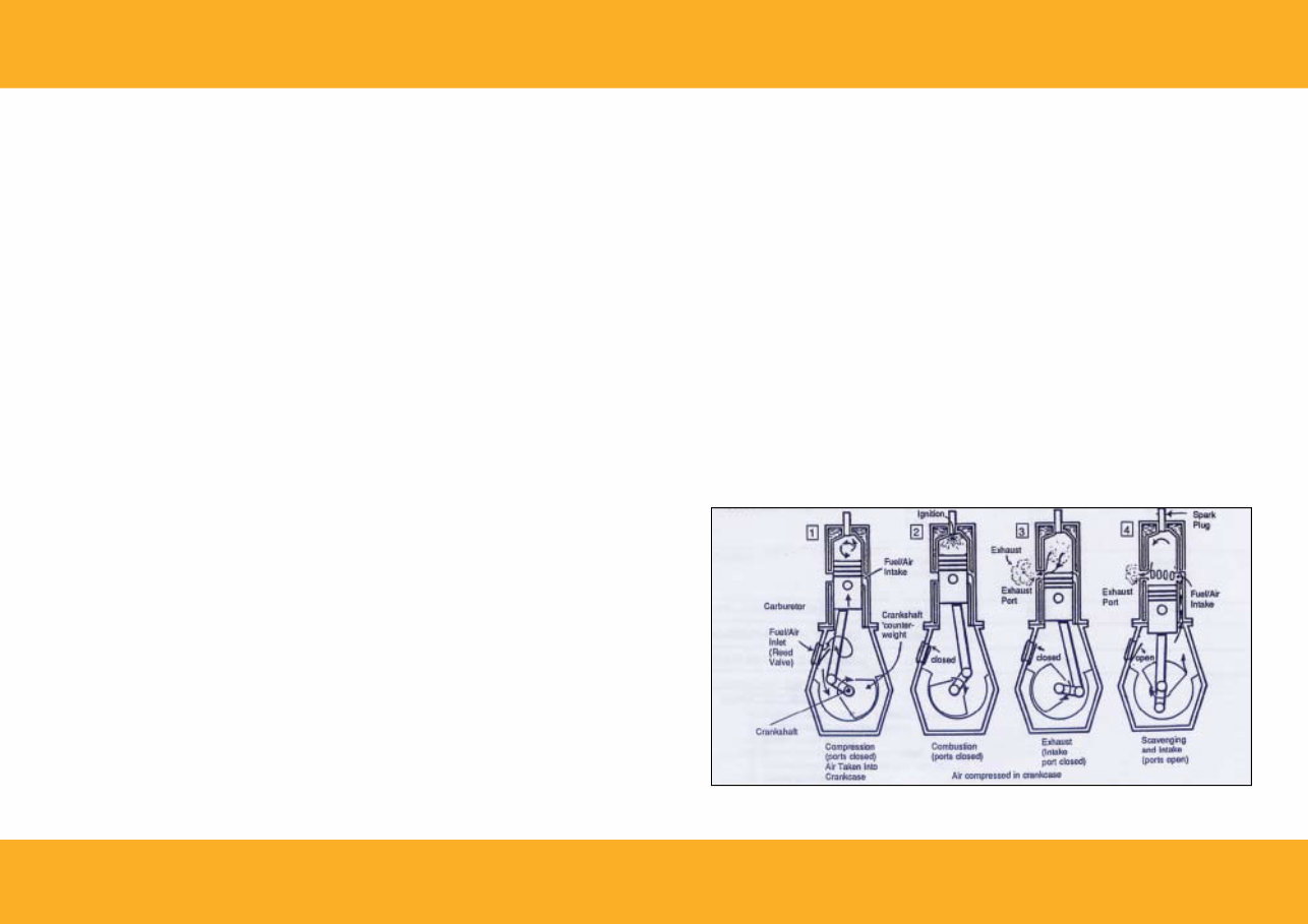
HOW A TWO STROKE ENGINE WORKS
The two-cycle engine is used almost exclusively in hand held
gasoline power equipment. The CS saw is of typical design, yet
incorporates unique features which maximize performance to
meet the heavy demands of the construction industry.
The carburetor performs the same function as with other engines.
It mixes the fuel with air in a fixed ratio to assure the most efficient
combustion of the fuel. The fuel vapor travels through the crankcase
on its way to the combustion chamber and provides a cooling
effect as well as critical lubrication to the engine components. Oil is
mixed with the gas to provide this lubrication.
The fuel vapor is drawn from the carburetor through the 1.
reed valve. Negative pressure created inside the crankcase
is the drawing force that opens the reed valve. The
negative pressure, or vacuum, is created in the crankcase
by two actions: the upward movement of the piston, and
the scooping action of the crankshaft counterweight.
At or near TDC (Top Dead Center), the ignition module 2.
provides the current (spark) to the spark plug. Starting
combustion. The burning and expanding gases push the
piston down, providing the power “stroke” needed to
turn the crankshaft.
As the piston moves downward, the exhaust port is 3.
exposed by the descending piston, releasing the hot
expanded gases (exhaust) out through the muffler.
As the downward movement of the piston continues, the 4.
intake port is exposed, allowing new fuel vapor to enter
the combustion chamber. Positive pressure, created in the
crankcase by the downward movement of the piston, forces
the vapor into the combustion chamber. Note that this
positive pressure in the crankcase also closes the reed valve.
As the piston begins its upward motion, beginning the
compression part of the cycle, the intake port is closed before
the exhaust port. Because of this, some unspent fuel vapor is
expelled through the exhaust port.
The cycle is now complete, and starts over again. Since
complete engine cycle takes two “strokes” of the piston, this
type of engine is known as “two stroke” or “two cycle”.
A thorough understanding of the principles of two cycle
engine operation is your key to servicing the saw. Review this
service manual carefully, and keep it nearby when working on
CS saw.
SPECIFICATION
Bore & Stroke 1.89” x 1.34” (48mm x 34mm)
Displacement 3.8 cu.in (61.5 cm3 )
Compression Ratio 7.5:1
Compression Pressure 150psig (1035kPa)
Piston Ring Gap 0.088” - 0.10” (2.24mm - 2.54mm)
Spark Plug NGK BPMR7A
Spark Plug Gap 0.025” (0.63mm)
Flywheel/Module Gap 0.012” - 0.016” (0.3mm - 0.4mm)
Fuel Capacity 0.7L
Fuel/Oil Mix Ratio 50:10
Clutch 3 Shoes Centrifugal
RPM Max H.P, Engine 8500
Blade Shaft RPM, No Load 5000
Starter Cord 35” x 0.157”
1

JCB CUT-OFF SAW | SPECIFICATIONS
TORQUE SPECIFICATION
Air Filter Cover Screw 40 - 50 in.lbs.
Cylinder Base Screw 130 - 142 in.lbs.
Cylinder Base Screw 130 - 160 in.lbs.
Spark Plug 177 - 204 in.lbs.
Carburetor Mounting Screws 44 - 53 in.lbs.
Muffler Bolts 53 - 62 in.lbs.
Reed to Crankcase Screws 62 - 70 in.lbs.
Clutch Nut 19 - 21 ft.lbs.
Shock Mounts 53 - 62 in.lbs.
Ignition Module Screws 30 - 40 in.lbs.
Decompression Valve 130 - 160 in.lbs.
Starter Pawl Screw 70 - 89 in.lbs.
Thread Size Torque
M4 30-40 in. lbs.
M5 40-53 in. lbs.
M6 53-70 in. lbs.
M8 133-166 in. lbs.
M10 22-25 ft. lbs.
M12 40-44 ft. lbs.
NOTES
2
JCB CUT-OFF SAW | TROUBLESHOOTING, DIAGNOSIS & REMEDIES
TROUBLESHOOTING, DIAGNOSTIC & REMEDIES
QUESTIONS TO ASK CUSTOMERS
Basic questions to ask customers when they bring a CS saw in for
repair:
What did it sound like when it stopped? 1.
Have you noticed the problem before? 2.
How long has it been since you last operated it? 3.
Is it hard to start? 4.
When was it tuned up and serviced last? 5.
Use a systematic approach. There are six systems involved in a CS
saw. These are:
Filter System
Fuel System
Ignition System
Pressure System
Cooling System
Lubrication System
Complete disassembly and assembly instructions are included later
in this book.
Always document everything you’re told about the saw for
reference on a repair tag or service order form. Review your notes
on what the customer told you about the saw, but do not take his
word as absolute proof. It is important to do your own diagnosis.
LOOK AT THE AIR FILTER FIRST
The first place to look is the air filter assembly. It is easy to sight
contaminants that have leaked in through the air filter assembly.
The inside of the rubber carburetor boot should be free from any
dust. The cause for this is most often operator error-not reinstalling
the air filter assembly correctly, or not cleaning and replacing filter
elements often enough.
QUICK CHECK OF PISTON AND CyLINDER
Another quick way to detect engine problems without a major
overhaul is to remove the muffler and look at the piston through
the exhaust port for signs of damage. A bluish discoloration means
the unit has overheated. Vertical scratches mean contaminants
have gotten inside the engine. Either case means a major overhaul
will be necessary to fix the saw.
START OF IN-DEPTH TESTING
Further in-depth testing will be necessary if inspection of the air
filter system and piston doesn’t reveal any probable causes for saw
malfunction.
Add fresh fuel mix in the fuel tank, and make sure the fuel pick-up
filter is situated in the bottom of the tank.
Make sure the carburetor mixture needles are at one turn open.
Pull the starter rope at least one dozen times to get a feel for the
engine’s compression.
CAUTION: It is permissible to start an engine without the
cutting arm installed, but DO NOT start it with a threaded clutch
driver to hold the clutch in place. Use a nut instead. There is a
very real danger of the clutch driver coming loose and striking
the operator.
3
JCB CUT-OFF SAW | TROUBLESHOOTING, DIAGNOSIS & REMEDIES
IF THE ENGINE WILL NOT START
If the engine will not start, pull the spark plug. If it is wet with fuel,
either the plug is faulty, the carburetor is flooding, the reed valve is
broken or the electrical system is not producing a spark.
Use a test plug to test the electrical system. A standard spark plug is
not recommended because it does not simulate the compressed
environment that a “test” plug does and, consequently, does not
require as much voltage to fire. A test plug will reveal problems
that a standard plug would not.
CAUTION: Keep the test plug AWAy from the cylinder opening
during testing so that it will not ignite fuel vapors escaping from the
combustion chamber.
If the engine has spark and the spark plug is dry, the fuel system
needs to be thoroughly examined.
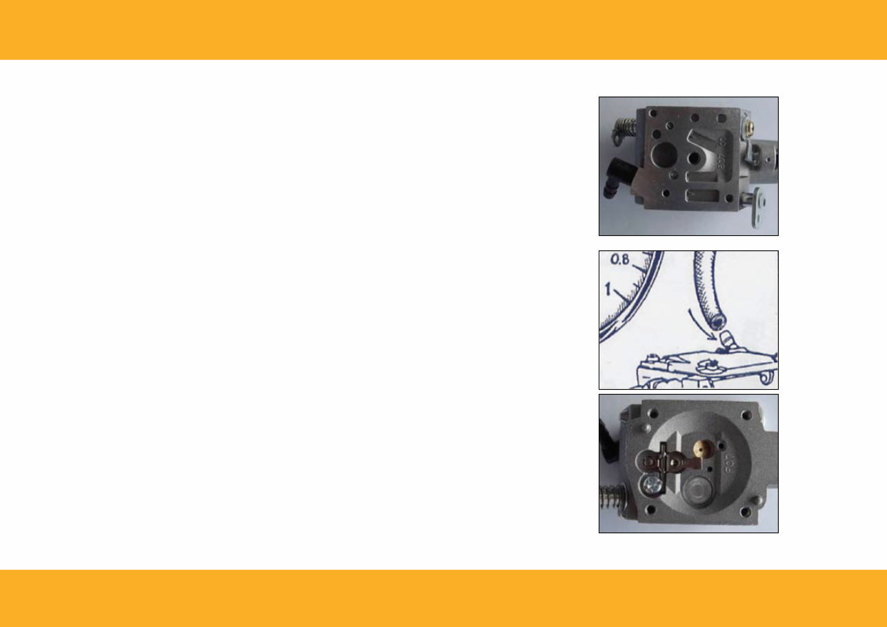
Disconnect the fuel line from the carburetor and check it for
cracks, pin holes or obstructions. Connect a pressure gauge to
one end of the hose, pinch the other end shut, pump air into the
hose and see if it holds pressure. Also inspect the fuel filter to see
if it needs replacing.
If the fuel line is in satisfactory condition, the carburetor needs to
be inspected.
CARBURETOR
The carburetor is designed so that it does not have to be removed
in order to perform maintenance. However, should you desire
to remove the carburetor for easier access to its components, it
is a simple matter of taking out the screws on either side of the air
intake passage.
This carburetor is specially designed for use on CS. While other
carburetors may fit, they are not governed to CS’s specifications
and could cause dangerous overspeeding of the blade.
Remove the carburetor pump cover and check the fuel inlet
screen for foreign material.
Whenever installing a carburetor diaphragm gasket kit, remember
that on the meter side the gasket goes next to the casting, the
diaphragm sets on top of it, and then the cover.
On the pump side, the diaphragm goes next to the casting, the
gasket sets on top of it, then the cover.
Sticking Needles:
Attach a pressure gauge to the fuel inlet nozzle of the carburetor
and pump pressure into the carburetor. When the metering
diaphragm is depressed, pressure should fall on the gauge. If it does
not, the carburetor inlet needle is stuck, causing fuel starvation.
In this case, the carburetor would have to be disassembled and
cleaned to solve the problem.
Test the reed valve for air tightness by holding it up to a light and
seeing if any light is visible between the reed and reed case.
Disassemble the reed valve and inspect the reed case for damage.
Look carefully for scratches, dents or abrasions on the surface area
that meets with the reed. Check the reed to see that it is not bent
or scratched.
4
JCB CUT-OFF SAW | TROUBLESHOOTING, DIAGNOSIS & REMEDIES
To clean the carburetor:
First scrub the outside thoroughly. Work on spread out sheets of
paper for a low-dust working surface. Cleanliness is important.
Use a cleaner specially suited for a carburetor, and a plastic bristled
brush.
Remove the high speed needle and the low speed needle. Inspect
them for damage, making sure they have not been bent from
overtightening. Clean them thoroughly.
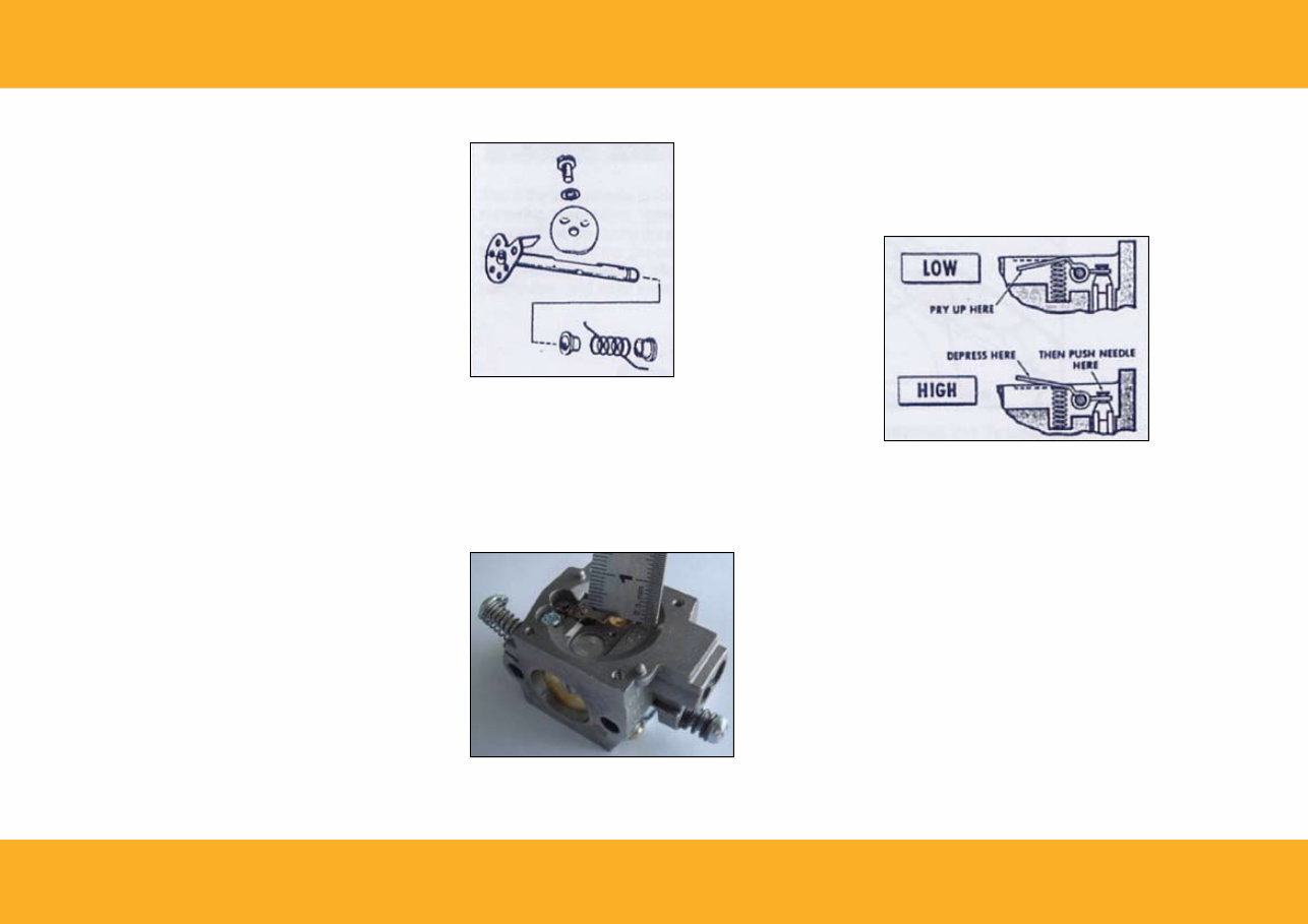
Remove the high speed and low speed Welsh Plugs. This can be
done with a drill or punch. The Welsh Plugs are comprised of a
screen, a clip, and a plug. Check the screen to see if any foreign
material has been trapped by it, causing disruption of fuel flow.
A scratch in this area would cause the carburetor to flood and
would have to be replaced.
Use a staking tool and small hammer to install the new Welsh
Plugs. Apply lacquer paint to the outside of the Welsh Plugs to
insure an airtight seal. Replace all three components of the Welsh
Plug when rebuilding the carburetor.
If the throttle return spring is broken, the throttle plate has to be
removed to access the spring. Scribe a mark on the throttle plate
before it is removed to provide a reference point for reinstallation.
The throttle plate appears to be round, but is actually oval.
Consequently, it is very important to install it in the same position.
If the plate is put in upside down or backwards, it may stick in the
throttle bore, resulting in an erratic idle. A screw in the middle of
the throttle plate is all that holds it in place. Always use Loctite on
the throttle plate and screw when installing.
Cold, hard starting and/or erratic idle may also be caused by wear
on the throttle and choke shafts. Check the chrome plating to see
if it has been worn off from vibration. The worn shafts will allow
dirt to work its way into the carburetor and cause damage to the
power head.
Connect the fork to the inlet needle for the installation of the
metering lever.
Use a straight edge to check its height. The lever should be flush
with the floor of the metering chamber.
A high lever will cause flooding. A low lever will cause poor
acceleration and poor idle.
To correct these conditions, hold the inlet needle end of the lever
in place and pry up or down on the other end of the lever until it
is flush with the floor of the metering chamber.
The one-way venting valve is located in the gas cap. Only
atmospheric pressure passes through this valve. An external vent
is not necessary.
5
JCB CUT-OFF SAW | TROUBLESHOOTING, DIAGNOSIS & REMEDIES
See if the inlet needle holds pressure before installing the metering
diaphragm, gasket and cover back in place.
Connect the pressure gauge to the carburetor and apply a
minimum of 10lbs. pressure. If the inlet needle does not hold
pressure, it will not allow even flow of fuel through the carburetor,
and must be replaced.
Place the gasket next to the casting, then connect the button on
the underside of the diaphragm to the fork of the inlet lever. The
carburetor is equipped with a governor that controls the maximum
speed of the engine.
The governor is vibration activated. The governor is made up of a
brass capsule, a calibrated spring, steel ball and seat.
JCB’s governor is unique to the CS. Best suited for diamond
blade cutting. When ordering a new governor, refer directly to the
number inscribed directly on the governor that is being replaced
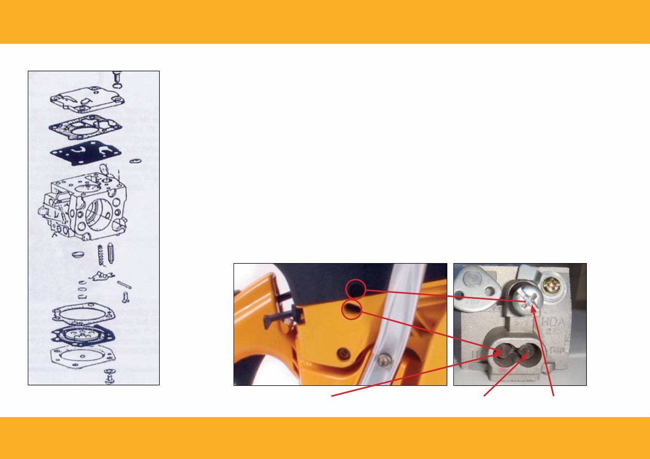
Setting the Carburetor:
Facing the adjusting hole, on its left side is a high speed screw. On
its right side is a low speed screw. Before leaving the factory, the
carburetor is basically set. If you would like to set the basic set
again, please close the engine, check if the air filter is clean, tighten
the H (high speed screw) and L (low speed screw) clockwise to
the end carefully, and then rotate the H speed screw 1 1/2 turns,
while L speed screw 2 1/4 turns( basic set). Run the engine for
five minutes. If the high speed of engine is too high or too low,
adjust T (idle speed screw) to make the rotation speed of engine
be approximate to 2500 rpm.
Adjust the low speed screw first. While the engine is idling, rotate
the low speed screw clockwise until the engine speeds up and
becomes too lean. Note the position of the needle slot, then turn
the screw out until the engine runs too rich. Again, note position
of the needle slot, then turn the screw back in, half way between
the two noted positions.
H (high speed screw) L (low speed screw) T (idle speed screw)
6

JCB CUT-OFF SAW | TROUBLESHOOTING, DIAGNOSIS & REMEDIES
To adjust the high speed screw, start the engine and run it wide
open. Lower the blade into a cut to put the engine under load.
Apply enough pressure to stall the clutch for three to five seconds.
Be careful, stalling the clutch for any longer than five seconds can
cause it damage. If the engine stalls when the clutch is stalled, the
mixture is too lean. Adjust the high speed screw 1/8 of a turn richer
and try the stall test again. Repeat the test if necessary.
It will lead to the decline of the power, overheated and malfunction
of the engine if the concentration of mixture which is set by H (high
speed screw) is too low. The high speed screw is used to adjust
the maximum power instead of maximum speed.
AIR LEAKS
An air leak is best detected when the engine is idling. The engine
will run stable for three to five seconds, then speed up, slow down,
then speed up again until it suddenly quits in a lean condition.
To test for air leaks, spray WD-40 around the cylinder base gaskets,
the carburetor and manifold gaskets, and the driveside crankcase
seal while the engine is idling in this lean condition. Watch for air
bubbles, which would indicate an air leak.
If this method does not reveal the air leak, remove the carburetor
and muffler and bland these areas off with the bland-off plates
provided in the air leak tester kit. Leave the spark plug in place,
attach a pressure gauge to the nipple fitting of the carburetor, and
apply approximately 8 lbs. of pressure to the crankcase. Put soapy
water around the gasket seals and watch for bubbles revealing a
leak. You may have to immerse the entire engine in a vat of water
or kerosene to detect the problem area.
The decompression valve may have a tendency to leak a little air.
This does not mean that it is faulty, but cleaning the decompression
valve will improve its seal. For the air leak test, you may find it
desirable to remove the decompression valve and block the socket
with the plug provided in the air leak test kit.
IGNITION SySTEM
Problem: Engine fails to start.
Check for spark using test plug. 1.
Check ignition switch 2.
Check all wires and connections. 3.
IF THERE IS NO SPARK
If there is no spark, you will need a continuity tester, a test spark
plug, and a high tension lead. The ignition module cannot be
serviced. It has to be replaced if it is not working.
Disconnect the ignition switch and turn the engine over. The
engine must be turned over at least 600 to 800 RPM to energize
the system. If the test plug produces a spark, the ignition switch is
faulty. Simply replace it.
If the switch is not the problem, disconnect the other end of the
switch wire from the ignition module. Replace the starter housing
and turn the engine over. If the test plug produces a spark this
time, it means that the switch wire is damaged and needs to be
replaced.
If the problem is still undetected, the next step is to test the flux
levels (magnetic pulling power) of the flywheel magnets using a
screwdriver. Experience will tell you what is adequate.
Check the gap between the flywheel and the ignition module. It
should be 0 .012” to 0.018”.
If the high tension lead passes a continuity and leakage test, it means
the ignition module has to be replaced.
LUBRICATION
Pistons scored from top to bottom mean the engine was not
getting adequate lubrication. When disassembled, the wrist pins
will be blue in color, the main bearings will be very dry, the spark
plug will be powdery white, and the inside of the muffler will be
very dry.
COOLING SySTEM
The cooling is comprised of three components: the fan housing,
flywheel and cylinder fins. It is important for an operator to clean
these parts regularly to prevent overheating.
7
JCB CUT-OFF SAW | DISASSEMBLy AND ASSEMBLy PROCEDURES
DISASSEMBLy AND ASSEMBLy PROCEDURES
Always empty the gas tank before starting to disassemble the saw.
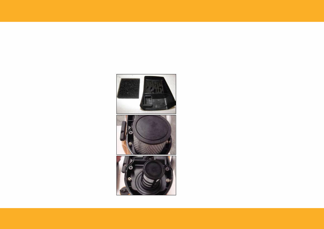
AIR FILTER
The filter system is made up of pre-filter sponge, paper filter, inner
filter. Prior to disassembly, clean the exterior of any dust or dirt
to avoid contaminates from entering the carburetor. Inspect the
washer gasket and filter housing gasket for damage.
Rinse the pre-filter sponge in warm soap water. Before fitting, soak
it in to the engine oil and squeeze out extra oil. Clean the inner
filter by using gasoline.
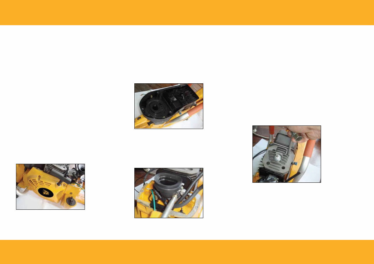
To get to the cylinder and piston, the following must be removed
in this order:
Cutting Arm (See page 18)
Starter Cover 1.
Filter fix foundation 2.
Carburetor 3.
STARTER COvER
The starter cover is held in place with four screws, two in the
bottom frame and two at the top.
FILTER FIx FOUNDATION:
The filter fix foundation is held in place by three screws.
CARBURETOR
The carburetor does not have to be removed to service it.
Loosen the two screws on either side of the carburetor throat.
Disconnect the choke throttle linkage and the fuel line. Now the
carburetor can be easily lifted out.
CyLINDER
Turn the crankshaft until the piston is in the lowest position. Then,
loosen and remove the four hex head bolts that hold the cylinder
to the crankcase. The cylinder should separate from the crankcase
with minimal effort.
Inspect the base gasket to ensure there has been no leakage. This
gasket should be replaced on reassembly of the saw.
Torque the four hex head bolts down to between 130 and 142
inch pounds. Be sure to use an “x” pattern when tightening these
bolts to assure an even seal.
A ring compressor provides an easy way to compress the rings
during installment of the cylinder, but if one is not available, it can
be done by hand.
8
You're Reading a Preview
What's Included?
 Lifetime Access
Fast Download Speeds
Online & Offline Access
Access PDF Contents & Bookmarks
Full Search Facility
Print one or all pages of your manual
$36.99
JCB CS-300 CS-350 Cut off Saw Service Manual
Viewed 53 Times Today

What's Included?
Lifetime Access
Fast Download Speeds
Online & Offline Access
Access PDF Contents & Bookmarks
Full Search Facility
Print one or all pages of your manual
$36.99

Secure transaction
What's Included?
Lifetime Access
Fast Download Speeds
Online & Offline Access
Access PDF Contents & Bookmarks
Full Search Facility
Print one or all pages of your manual
Description
Get your hands on the comprehensive service manual for the JCB CS-300 and CS-350 cut off saws. This manual is an invaluable resource for professional mechanics and DIY enthusiasts alike. It contains 18 pages of essential technical information, providing detailed insights into the maintenance and repair of these powerful cut off saws.
Whether you're looking to troubleshoot an issue or carry out routine maintenance, this manual equips you with the knowledge needed to keep your JCB cut off saws in optimal condition. With its clear and concise instructions, it's an indispensable tool for anyone working with these machines.


