


Portable Power
P.O. Box 868 -- 501 SanfordAve
Mocksville, N.C. 27028
SERVICE MANUAL FOR
ELECTRICAL/ELECTRONIC
www.portablepower.irco.com
Book No. 22235428 (11/03)
P425AWIR (7/120)
XP375AWIR (9/110)
HP375AWIR (10/105)
VHP300AWIR (14/85)
P600WIR
HP450WIR
VHP400WIR

1 ( )
Book No. 22235428 (11/03)
P425AWIR Family Electrical Manual
TABLE OF CONTENTS
SECTION 1 ....... Manual Description
SECTION 2 ....... General Information And Operational Theory
SECTION 3 ....... Service Tools
SECTION 4 ....... Electronic Systems Troubleshooting
Procedures And Techniques
SECTION 5 ....... System Schematic Diagrams
SECTION 6 ....... Electronic Component Location Drawings
SECTION 7 ....... Individual Circuit Diagrams
SECTION 8 ....... Electrical Connector Information
SECTION 9 ....... Electrical Parts List
SECTION 10 ...... Alerts and Shutdowns List
SECTION 11 ...... Recommended Spare Parts
SECTION 12 IR Engine ....

2 ( )
Book No. 22235428 (11/03)
P425AWIR Family Electrical Manual
SECTION 1
MANUAL DESCRIPTION
This manual contains all of the information concerning the electrical and electronic systems for
the P425 Family of compressors. It provides all information necessary to service, troubleshoot
and order parts for this machine.
It is organized into 12 sections.
Sections 2 -- 4 cover systems operation and troubleshooting procedures.
Sections 5 -- 7 have location diagrams, drawings of specific circuits and systems schematics.
Section 8 has information concerning the electrical connectors used, including removal and re-
placement.
Section 9 contains the parts list with ordering information.
Section 10 contains the list of Alerts and Shutdowns.
Section 11 contains a list of recommended spare parts for servicing.
Section 12 contains engine information.

3 ( )
Book No. 22235428 (11/03)
P425AWIR Family Electrical Manual
SECTION 2
GENERAL INFORMATION
and
OPERATIONAL THEORY

4 ( )
Book No. 22235428 (11/03)
P425AWIR Family Electrical Manual
GENERAL INFORMATION AND OPERATIONAL
THEORY
General
The P425 Family of machines has an electronic
monitor and control system to provide discharge air
pressure control and engine and package monitor
functions. The system uses the WEDGE controller to
perform these functions. The electrical system
connects all the necessary switches, sensors and
transducers to the WEDGE controller in order for it to
perform the monitor and control functions.
WEDGE Controller
The WEDGE controller is the heart of the machine
monitor and control system. It provides data
collection, alarming and control functions for
compressor operations. It is a microcontroller based
unit with analog and digital inputs and outputs.
The WEDGE controller is attached to the back of the
control panel. The LED annunciators are part of the
front panel of the WEDGE. They can be seen through
the laminate on the front of the control panel.
The WEDGE is attached to the control panel with four
#10 size nuts.
The first function of the WEDGE controller is to scan all
analog and digital inputs at a fixed interval. These
inputs are scanned every 50 milliseconds. The analog
values are then compared against minimum and
maximum values and an ALERT or SHUTDOWN is
issued, if a value is out of range. The various ALERTS
and SHUTDOWNS are listed in Section 10 of this
manual.
The second function of the WEDGE controller is
machine discharge pressure control. The WEDGE
monitors the regulation system air pressure and varies
the engine throttle to maintain the setpoint discharge
air pressure. The setpoint pressure is set using the
regulator on the separator tank.
The third function of the WEDGE controller is to
communicate with the diesel engine via the J1939
CAN network. It retrieves diagnostic information over
J1939.
5 ( )
Book No. 22235428 (11/03)
P425AWIR Family Electrical Manual
FIGURE 2--1
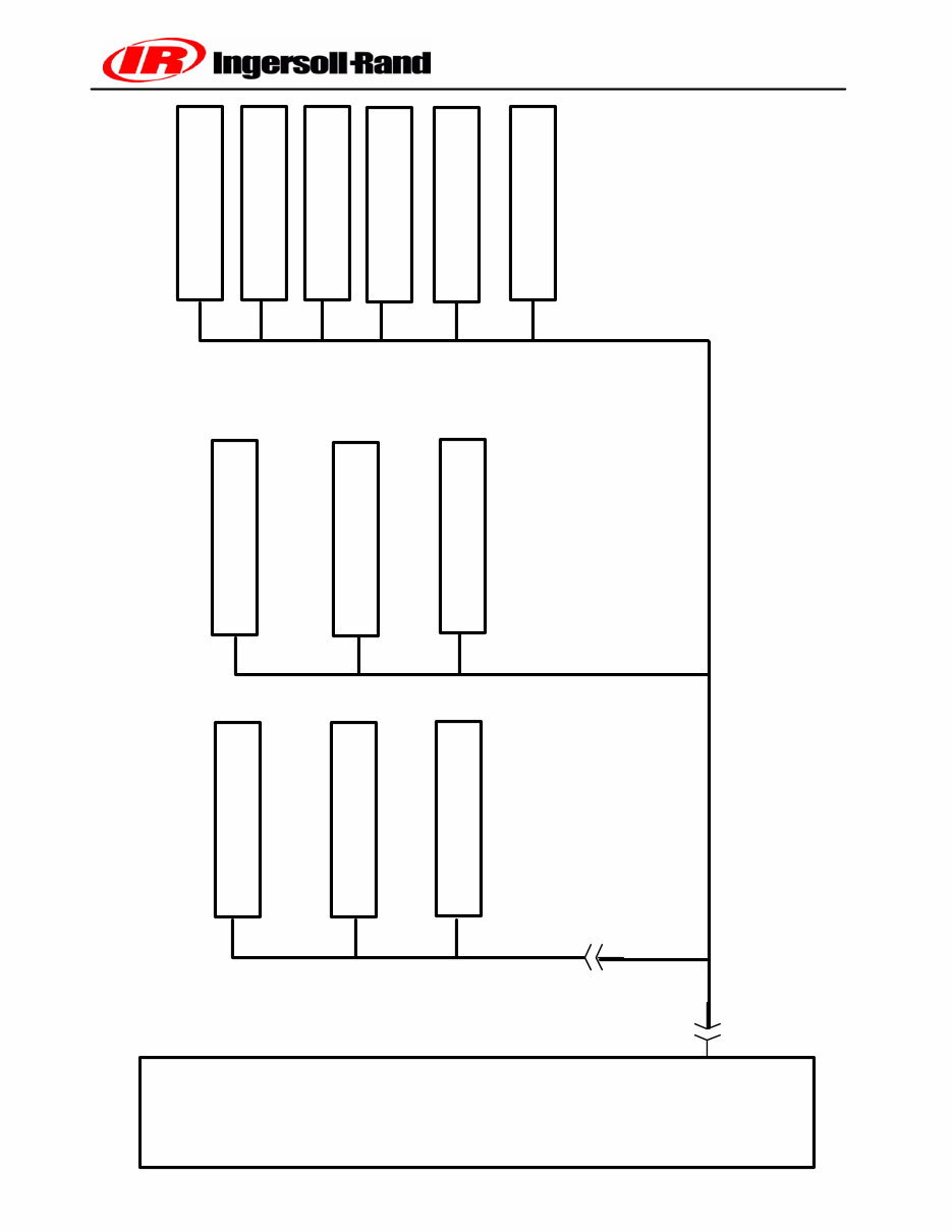
P425/P600 HARNESS SYSTEM SCHEMATIC
WEDGE
Controller
CONTROL PANEL SWITCHES
GAUGES
24VDC HEATERS
ENGINE ECM DIAGNOSTIC
INTERFACE
ESTOP SWITCHES
SOLENOID VALVES
SPEED SENSOR
FUEL LEVEL SWITCH
PRESSURE TRANSDUCERS
TEMPERATURE SENSORS
BATTERY STARTING AND
CHARGING SYSTEM
W1
P4
W1
P1
HOURMETER
CONTROL PANEL HARNESS
W1 W1
6 ( )
Book No. 22235428 (11/03)
P425AWIR Family Electrical Manual
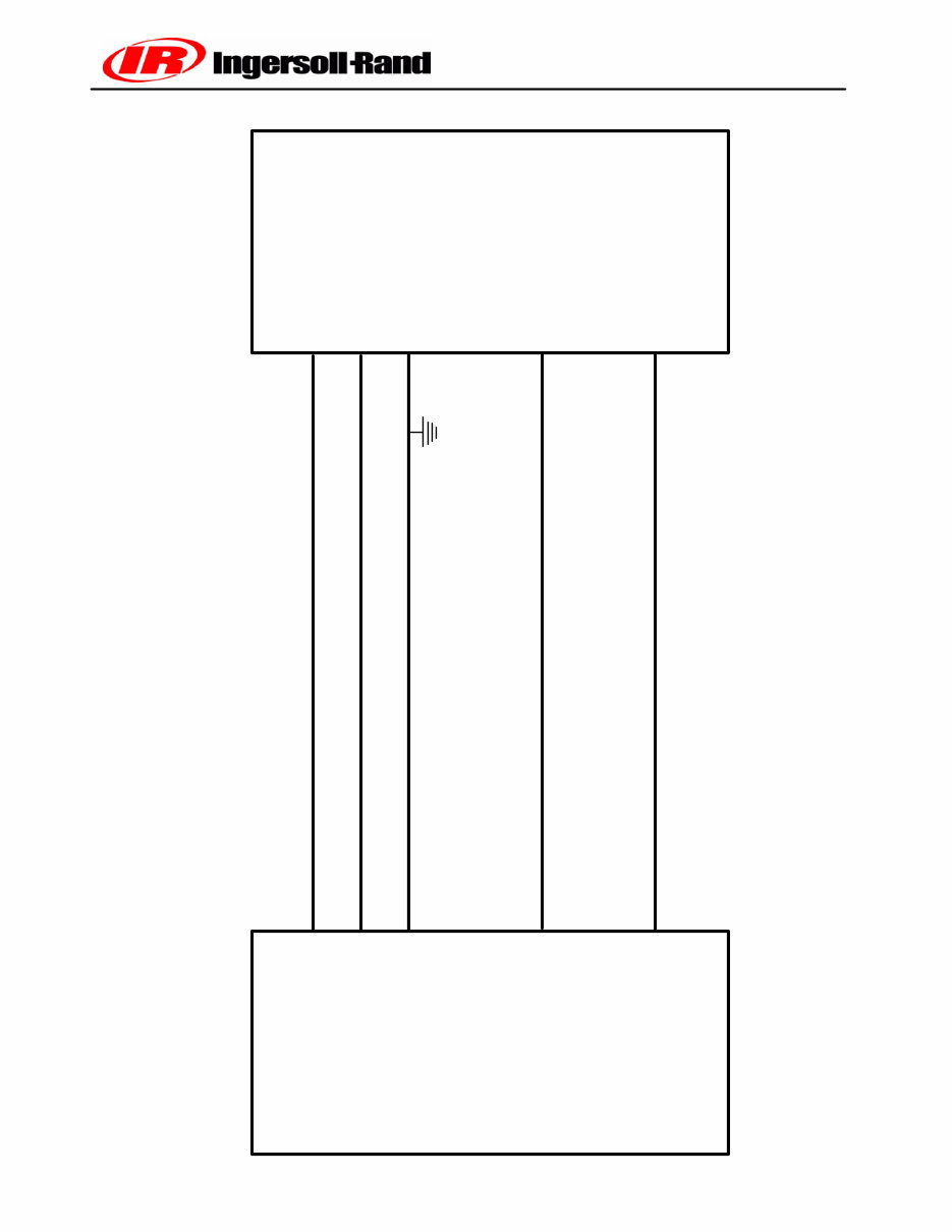
FIGURE 2--2
WEDGE
CONTROLLER
WEDGE TO ENGINE INTERFACE
IR ENGINE
J1--34
J1--35
J1--24
IR
41RD5AE
61IRF8TE
ENGINE
CONTROLLER
J50--G1
J50--J1
J50--A2
J50--F2
CAN LO
CAN HI
CANSHLD
J1--38
J1--13
ANALOG THROTTLE RANGE = 1.10VDC (1400RPM) TO 3.7VDC (2400 RPM)
ANALOG THROTTLE
KEY SWITCH
7 ( )
Book No. 22235428 (11/03)
P425AWIR Family Electrical Manual
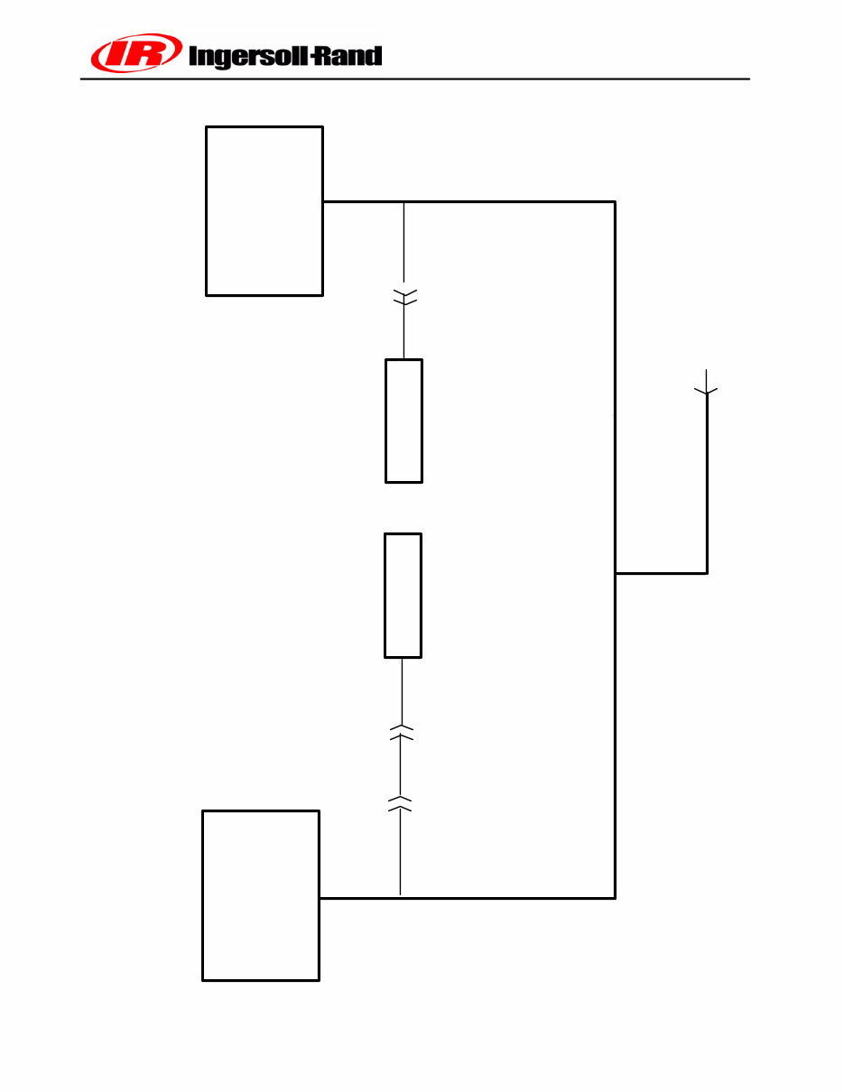
P425/P600 J1939 CAN COMMUNICATIONS SCHEMATIC
ENGINE ECM
WEDGE
CONTROLLER
TERMINATOR
TERMINATOR
ENGINE DIAGNOSTICS JACK
J57
R4
P11
R5
P10
FIGURE 2--3
P6

8 ( )
Book No. 22235428 (11/03)
P425AWIR Family Electrical Manual
The wedge uses an analog signal to communicate
with the John Deere engine. This signal has a range of
1.1V to 3.7V. This range corresponds to an engine
speed range of 1400 to 2400 RPM.
Figure 2--2 shows the signals between the engine
controller and the WEDGE controller.
Sensors and Transducers
The electronics system contains sensors and trans-
ducers that are used to collect data from the compres-
sor. The temperature is measured by a thermistor.
This device exhibits a change in resistance as the tem-
perature changes. The resistance causes an input
voltage change to the WEDGE controller input and is
interpreted as a temperature change.
The electronics system also uses pressure transduc-
ers to measure compressor pressure changes. These
devices have an output signal of .45 VDC to 4.5 VDC,
corresponding to 0 psi and the maximum measured
psi for a particular device. The maximum pressure
transducer ranges are 100 or 225 psi. The 100 and
225 psi devices are gauge pressure devices. These
transducers are provided with 5 VDC excitation to
power the device. These are three wire devices: ex-
citation, signal and ground.
Digital Inputs and Outputs
The WEDGE controller scans digital inputs such as
switch contacts. These are either “ON” (24VDC) or
“OFF” (0 VDC). These digital inputs are connected to
switches within the package such as the key start
switch, air filter switches and IQ filter switches.
The WEDGE controller provides 24 VDC digital
outputs to control solenoids, start compressor and DC
heaters. These are 24 VDC “ON” and 0 VDC “OFF”.
They are current limited and short circuit protected.
Controller Outputs
The WEDGE controller has four types of outputs: fre-
quency, pulse width modulated, analog and 24VDC
digital (ON/OFF). The analog output is used as the
throttle signal to the engine.
The WEDGE varies the analog signal from 1.25 to 4.25
volts, corresponding to 1400 to 2100 RPM. This signal
is used with the John Deere engine. The frequency
throttle signal is used with the Cummins engine and
the pulse width modulated signal is used with the CAT
engine.
Pressure Control
The discharge pressure is controlled by manipulating
the engine speed and compressor inlet valve position.
The inlet valve position is controlled pneumatically and
the engine speed is determined by the WEDGE con-
troller. The WEDGE measures the pneumatic system
regulation pressure and computes an engine throttle
setting. This throttle setting is sent to the engine via the
frequency throttle, Analog, PWM or J1939 throttle, de-
pending on which technique is used. The engine con-
troller will control engine speed to this throttle setting.
Electronic Engine -- P425 Family of Machines
The P425 Family of machines contains an emissions
certified diesel engine. In order to meet the emissions
requirements, the engine has an electronic control
system.
The control system handles all monitor, alarm and
control functions for the engine. The WEDGE control-
ler communicates with the engine controller over the
J1939 CAN network.
The WEDGE controller sends throttle settings to the
engine and receives diagnostic and run time data from
the engine over the J1939 CAN network. An analog
throttle interface is currently used with the engine.
Figure 2--2 shows the connections between the
WEDGE controller and the engine controller.

9 ( )
Book No. 22235428 (11/03)
P425AWIR Family Electrical Manual
J1939 Data Link
The CAN network is a single pair shielded cable
located with the W1 main harness. Figure 2--3 shows
a layout of the CAN harness or “backbone” as it is
referred to. The termination resistors (Terminator) are
important to prevent reflections on the transmission
line and must be in place for the network to function
properly.
The engine diagnostics connector is located on the left
side of the engine. This is used to connect the engine
manufacturer’s service tools to the CAN network. This
connector also provides 24 VDC to power these
service tools.
Electrical System
The electrical system consists of the wiring harnesses
and associated electrical devices such as relays,
switches, lights, solenoids and alarm horn. There is
one wiring harnesses in the P425 machine.
P/N 22199061 W1 Chassis Main Harness
The schematic diagrams show the connections for this
harness. Figure 2--1 is a system schematic showing
harness connection with devices and controllers. Sec-
tion 8 includes information on connectors used in the
harness.
The electrical circuits are protected using ATC style
fuses. A fuse should only be replaced with one of the
same rating. Replacing a fuse with one of a large
rating could lead to harness damage. If a fault occurs
and the circuit does not have the appropriate size fuse,
wires could be burned in the harness and damage
other circuits.
Machine ID
Software versions 1.60 and greater use software to
set the machine ID. Versions less than 1.60 use an ID
resistor plug, R2. The ID plug is located behind the
control panel box on the W1 harness trunk. The
resistor plugs are molded in colors for easy
identification. Refer to Section 7, Individual Circuit
Diagrams and the page entitled R @ MACHINE ID
PLUG for details.
It is recommended that all machines be upgraded to
Version 1.60 or greater. The software set machine ID is
much more reliable than the resistor plug.
You're Reading a Preview
What's Included?
 Lifetime Access
Fast Download Speeds
Online & Offline Access
Access PDF Contents & Bookmarks
Full Search Facility
Print one or all pages of your manual
$30.99
Ingersoll-Rand P425AWIR, XP375AWIR, HP375AWIR, VHP300AWIR, P600WIR HP450WIR, VHP400WIR Electrical / Electronic Service Repair Ma
Viewed 11 Times Today

What's Included?
Lifetime Access
Fast Download Speeds
Online & Offline Access
Access PDF Contents & Bookmarks
Full Search Facility
Print one or all pages of your manual
$30.99

Secure transaction
What's Included?
Lifetime Access
Fast Download Speeds
Online & Offline Access
Access PDF Contents & Bookmarks
Full Search Facility
Print one or all pages of your manual
Description
This Service Repair Manual is an essential resource for anyone working with the Ingersoll-Rand P425AWIR, XP375AWIR, HP375AWIR, VHP300AWIR, P600WIR, HP450WIR, VHP400WIR models. It contains high-quality diagrams and detailed instructions for servicing and repairing your equipment. Whether you are a professional mechanic or a DIY enthusiast, this manual provides valuable insights into:
- General information
- Service maintenance information
- Lubrication system
- Fuel system
- Engine removal
- Cylinder head/valve
- Cylinder/piston
- V type belt driving system/kick starter
- Final driving mechanism
- Alternator/starting clutch
- Crankshaft/crankcase
- Cooling system
- Body cover
- Front brake and front wheel
- Steering/front suspension
- Rear brake/rear wheel/rear cushion
- Electrical equipment
- Electrical diagram
This comprehensive manual is available in PDF format, compatible with all versions of Windows and Mac. It is a valuable resource that can save you time and money on maintenance and repairs. Get instant access to this indispensable guide and enhance your understanding of your Ingersoll-Rand equipment.


