

STIHL 009/010/011 Chainsaw Service & Repair Manual
What's Included?
Fast Download Speeds
Online & Offline Access
Access PDF Contents & Bookmarks
Full Search Facility
Print one or all pages of your manual
STIHL 009, 010, 011
1
SERVICE MANUAL
STIHL 009, 010, 011
FOREWORD
This Service Manual covers model 010
chain saws up to machine number
7 900 000 as well as later machines
unless technical information bulletins
have been issued in the meantime
with updated repair procedures.
Models 009 and 011 have substantially
the same constructional features as
model 010 chain saws. This Service
Manual can therefore be used for the
009 and 011 chain saws as well.
In the event of faults it is quite possible
that a single fault may have several
causes. It is therefore advisable to
consult the "Troubleshooting Chart"
in each chapter when tracing faults.
We also recommend that you make
use of the exploded views in the
illustrated parts lists when carrying out
repair work.
This service manual and all technical
information bulletins are intended
exclusively for the use of STIHL
servicing dealers and staff and must not
be passed on to third parties.
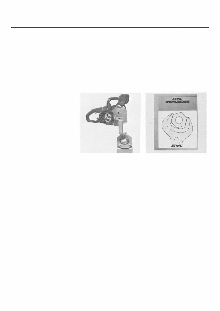
SPECIAL TOOL MANUAL
Repair work is made considerably Our special tool manual illustrates
easier if the chain saw is mounted on and lists the part numbers of ail
assembly stand 5910 850 3100. The available machine-related tools as
saw is easily secured to the stand by well as general purpose tools for all
means of the bar mounting stud and machines.
collar nut.
The special tool manual is available
While on the assembly stand the chain in several languages and can be
saw can be swivelled into any required ordered by quoting the appropriate
position within a certain range to suit part number listed hereunder.
the repair in question. This not only
has the advantage of keeping the German 0455 901 0023
component in the most convenient English 0455 901 0123
position for the repair but also leaves French 0455 901 0223
both hands free for the work and thus Spanish 0455 901 0323
effects a considerable time saving. Yugoslav 0455 901 0423
Swedish 0455 901 0523
Italian 0455 901 0723
Portuguese 0455 901 1223
STIHl
Andreas Stihl
Postfach 1760
D-7050 Waiblingen

STIHL 009, 010, 011 2
CONTENTS
1. Specifications 4 3.7 Installation of 4.5.2 Adjusting Breaker-
Crankshaft Controlled Ignition 34
1.1 Engine 4 - Assembly of 4.6 Magneto Edge Gap
1.2 Fuel System 4 Crankcase 16 on Breaker-
1.3 Ignition System 5 3.8 Leakage Testing the Controlled Ignition 34
1.4 Tightening Torques 5 Crankcase 18
1.5 Cutting Attachment 6 3.8.1 Pressure Test 19
1.6 Weights 6 3.8.2 Vacuum Test 20
1.7 Special Accessories 6 3.8.3 Replacing the Oil 5. Rewind Starter 35
Seals 20
5.1 Construction and
Operation 35
2. Clutch, Chain Drive 5.2 Troubleshooting Chart 35
and Chain Brake 7 5.3 Disassembly 36
4. Ignition System 21 5.4 Replacing the
2.1 Construction and Operation 7 Starter Rope 36
2.1.1 Clutch and Chain 4.1 Construction 21 5.5 Replacing the
Sprocket 7 4.2 Description of Rewind Spring 37
2.1.2 Chain Brake 8 Operation 21 5.6 Tensioning the
2.2 Troubleshooting Chart 8 4.2.1 Breaker-Controlled Rewind Spring 37
2.3 Repair 9 Magneto Ignition 22 5.7 General Maintenance 37
2.3.1 Disassembly 4.3 Troubleshooting
and Assembly of Clutch 9 Chart 23
2.3.2 Disassembly of 4.4 Function and Repair
Chain Brake 10 of Components 24 6. AV Handle System 38
2.3.2.1 Assembly of Chain Brake 10 4.4.1 Spark Plug 24
4.4.2 Ignition Lead 25 6.1 Construction and
4.4.3 Ground Lead Contakt 26 Operation 38
4.4.4 Flywheel 27 6.2 Repair 38
3. Engine 11 4.4.5 Ignition Armature 28
4.4.5.1 Resistance Test on
3.1 Construction 11 Primary Winding 29 7. Chain Lubrication 39
3.2 Troubleshooting Chart 11 4.4.5.2 Resistance Test on
3.3 Exposing the Cylinder 12 Secondary Winding 29 7.1 Construction and
3.4 Disassembly of 4.4.5.3 Disassembly and Operation of
Cylinder and Piston 12 Assembly 29 Oil Pump 39
3.5 Assembly of Piston 4.4.6 Condenser 30 7.2 Troubleshooting Chart 40
and Cylinder 14 4.4.7 Contact Set 31 7.3 Oil Tank/Tank Vent 41
3.6 Disassembly of Crank- 4.5 Ignition Timing 32 7.4 Notes on Repair 41
case - Removal of 4.5.1 Checking Breaker- 7.5 Disassembly and Repair
Crankshaft 15 Controlled Ignition 33 of Pump Housing 42

STIHL 009, 010, 011 3
8. Fuel System 43
8.1 Construction and
Operation of Carburetor 43
8.1.1 Operation of Fuel Pump 43
8.1.2 Operation of Carburetor 43
8.2 Troubleshooting Chart 45
8.3 Leakage Test
(Pressure Test)
on Carburetor 47
8.4 Disassembly of
Carburetor 47
8.5 Repair of Carburetor 48
8.6 Carburetor Adjustment 50
8.6.1 Notes for Fine Adjust-
ment of Carburetor 50
8.7 Fuel Line 51
8.8 Tank Vent 51
8.9 Air Filter and
Choke Valve 52

STIHL 009, 010, 011 4
1. SPECIFICATIONS
1.1 Engine Single cylinder two-stroke engine with specially processed cylinder bore
Displacement 009, 010: 37 cm³ (2.26 cu. in)
Bore 009, 010: 36 mm (1.42 in)
Displacement 011: 41 cm³ (2.50 cu. in)
Bore 011: 38 mm (1.50 in)
Stroke: 36 mm (1.42 in)
Compression ratio: 9.8:1
Max. torque: 1.8 Nm (1.3 Ibf. ft)
at 4500 r.p.m.
Rated speed, off load with
bar and chain: 9500 - 9800 r.p.m.
Mean idle speed: 2200 - 2400 r.p.m.
Crankshaft: Drop forged
Crankshaft bearings: 2 needle sleeves
Crankpin: 13 mm (0.51 in) dia.
Big-end bearing: Cylindrical rollers without cage
Piston pin: 9 mm (0.35 in) dia.
Small-end bearing: Needle sleeve
Rewind starter: Pawl engagement with automatic
starter rope rewind mechanism
Starter rope: 3.5 mm (0.14 in) dia.,
960 mm (38 in) long
Clutch: Centrifugal clutch without
linings, 64 mm (2.5 in) dia.
Clutch engages at: 3200 - 3300 r.p.m.
Crankcase leakage test
with overpressure: 0.5 bar (7.1 Ibf/in²)
with vacuum: 0.5 bar (7.1 Ibf/in²)
1.2 Fuel System Carburetor: All-position diaphragm carburetor
with integral fuel pump
Adjustment:
High-speed adjustment screw H: Open 1 turn
Low-speed adjustment screw L: Open 1 turn
(basic setting starting with screws
lightly against their seats)
Carburetor leakage test
with overpressure: 0.4 bar (5.7 Ibf/in²)
Fuel capacity: 0.26 L (0.55 US pt)

STIHL 009, 010, 011 5
Fuel mixture: Regular grade gasoline and
branded two-cycle engine oil
Mix ratio 1:40 with STIHL
two-cycle engine oil: 1:25 with
other branded two-cycle
engine oils
Air filter: Large area felt mat
1.3 Ignition System Type: Breaker-controlled magneto
ignition
Magneto edge gap: 5 mm (0.2 in)
Ari gap: 0.2 mm (0.008 in)
Ignition timing: 1.8-2.1 mm before T D.C.
Ignition advance angle: 23°-24°
Breaker point gap: 0.3-0.4 mm (0.012-0.016 in)
Condenser: Capacitance 0.17 μF
Ignition armature: Coil winding resistance
Primary Secondary
0.8-1.3 Ω 7.2-8.8 kΩ
Spark plug (suppressed): Bosch WSR 6 F or
Champion RCJ 6 Y
Heat range 200
Electrode gap 0.5 mm (0.02 in)
Spark plug thread: M 14x1.25; 9.5 mm (0.37 in) long
1.4 Tightening Torques Crankshaft nut
(ignition side) M 8x1: 30 Nm (22.1 Ibf. ft)
Clutch (sprocket side): 30 Nm (22.1 Ibf. ft)
M 6 socket head screws: 10 Nm (74 Ibf. ft)
M 5 pan head screws: 5 Nm (3.7 Ibf. ft)
M 4 pan head screws: 2.5 Nm (1.8 Ibf. ft)
M 5 nuts: 5 Nm (3.7 lbf. ft)
Spark plug: 25 Nm (18.4 Ibf. ft)

STIHL 009, 010, 011 6
1.5 Cutting Attachment Guide bars: STIHL Standard guide bars
without stellite-tipped nose
STIHL Duromatic guide bars
with stellite-tipped nose
STIHL Rollomatic guide bars
with sprocket nose
All types with corrosion-resistant
finish and induction hardened rails
Bar lengths: Duromatic 30 and 35 cm (12 and 14 in)
Rollomatic 30, 35 and 40 cm
(12, 14 and 16 in)
Chain: 9.32 mm (3/8")-Oilomatic-Picco
Chain sprocket: 6-tooth for 3/8" Picco pitch
Chain speed: 13 m/s (42.6 ft/sec) at 7000 r.p.m.
Chain lubrication: Speed-controlled oil pump with
Diaphragm
Oil delivery rate: 6-12 cm
3
/min (0.37-0.74 cu. in/min)
at 7000 r.p.m.
Oil tank capacity: 0.28 L (0.59 US pt)
1.6 Weights Model: 009 010 AV 011 AV
Dry powerhead with
30 cm bar and chain: 4.3 kg 4.6 kg 4.7 kg
(9.51 b) (10.1lb) (10.4Ib)
1.7 Special Accessories STIHL repair kit 009, 010, 011 1120 900 5000
Set of gaskets 009, 010, 011 1120 007 1050
STIHL 009, 010, 011 7
The construction of the clutch is
identical on both models of the saw
(with and without chain brake).
While the engine is running at idle
speed there is no change in the
shape of the clutch, i.e. its outside
diameter remains constant because
the rigidity of the laminate block's
smallest cross section is greater
than the centrifugal force applied.
As engine speed increases the outer
diameter of the clutch becomes
larger when the centrifugal force
overcomes the rigidity of the
laminate block. This causes the
clutch to be pressed against the
clutch drum and thus transmit engine
torque positively via the clutch drum
and the chain sprocket to the saw
chain.
The rigidity of the clutch is designed
so that the clutch begins to make
contact with the clutch drum at an
engine speed of approx. 3200 r.p.m.
The clutch engages fully above this
speed. It is therefore very important
to set the carburetor to the correct
idle speed in order to insure that
the clutch engagement speed
(3200 r.p.m.) is not reached when
the engine is idling.
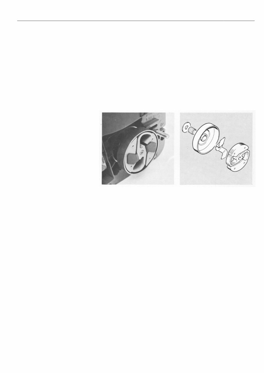
The transmission of power from the
engine to the saw chain is effected
via a centrifugal clutch which has no
linings.
The clutch consists of a laminate block
made up of seven separate metal
sheets which are riveted together. The
laminate block is screwed to the
crankshaft. A cranked U-plate is fitted
between the laminate block and the
clutch drum and acts as a guard which
prevents parts of the clutch coming
adrift in the event of breakage.
Clutch with cranked U-plate in position Component parts of clutch
2. CLUTCH,
CHAIN DRIVE AND
CHAIN BRAKE
2.1 Construction
and Operation
2.1.1 Clutch and
Chain Sprocket

STIHL 009, 010, 011 8
2.1.2 Chain Brake
The chain brake is a spring-loaded The chain brake is disengaged by The chain brake is engaged by
band brake without any friction linings. pulling the hand guard back toward moving the hand guard toward the
Its main components are the brake the handlebar. This movement is bar nose. This movement unlatches
band, tension spring, hand guard and transmitted via a lever system which the locked brake lever and causes
the lever system. preloads the tension spring and re- the brake band to be clamped
leases the brake band. around the clutch drum by the force
The chain brake is actuated via the of the preloaded tension spring. The
hand guard which can be used to The actuating lever, which is attached cluch drum and saw chain are
disengage or engage the brake. to the hand guard, remains locked in brought to a standstill in a split
the idle position after the operator second.
releases the hand guard.
2.2 Troubleshooting Chart
Condition Cause Remedy
Saw chain turns at idle speed Engine idle speed too high Readjust at idle speed
adjusting screw
Clutch broken Fit new clutch
Excessive chain sprocket wear Incorrect chain tension Tension chain correctly
Saw chain does not stop Tension spring broken Fit new tension spring
immediately when chain brake is
actuated
STIHL 009, 010, 011 9
2.3 Repair
2.3.1 Disassembly and
Assembly of Clutch
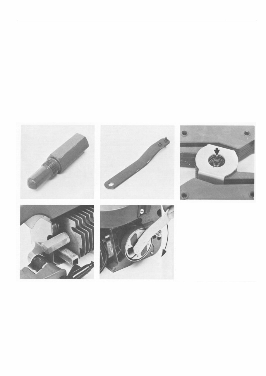
First remove the chain sprocket cover Caution: The clutch has a lefthand
and the cutting attachment. On Quick- thread - unscrew it clockwise!
stop models it is necessary to dis-
engage the chain brake so that the After unscrewing the clutch, remove the
brake band releases the clutch drum. chain sprocket, needle cage and thrust
washer from the crankshaft. Examine
Take out the spark plug and fit the clutch for signs of cracks or breaks.
locking screw in its place. Use the If hairline cracks are found in the
special wrench to turn the clutch and sprung part of the clutch, fit a new
the crankshaft clockwise until the clutch. The cranked U-plate should
piston head butts against the locking also be inspected for hairline cracks.
screw. Now use wrench to unscrew If any are found, fit a new Cranked
the clutch. U-plate. Wash needle cage, thrust
washer and stub of crankshaft with
clean gasoline. Replace needle cage
if it is faulty.
Lubricate needle cage, thrust washer
and stub of crankshaft with
antifriction bearing grease before
assembly. When refitting the clutch
make sure that the side on which the
thread is counterbored to a depth of
about 2 mm (0.08 in) faces the
crankcase. Tighten down clutch
with the wrench to a torque load of
30 Nm (3.0 kpm).
Top: Top:
Locking screw 1107 191 1200 Wrench 1113 890 3600
Bottom: Bottom:
Locking screw in position Unscrewing the clutch Counterbored side of clutch
STIHL 009, 010, 011 10
2.3.2 Disassembly of
Chain Brake
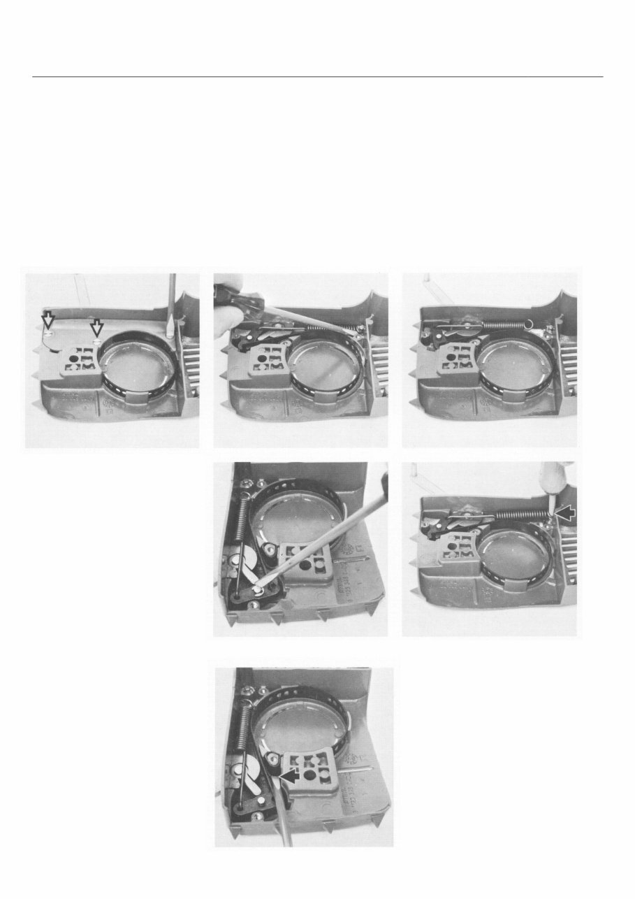
2.3.2.1 Disassembly of
Chain Brake
Top:
Detaching tension spring Top:
Brake band, brake lever and tension spring in
Center: position
Removing retaining washer
Bottom:
Bottom: Fitting tension spring with installing tool
Removing plastic cover Removing brake band 1117 890 0900
The chain brake components are inte-
grated in the chain sprocket cover. It
is therefore necessary to remove the
sprocket cover to gain access to the
brake components. After removing
the sprocket cover, engage the chain
brake, unscrew the plastic cover and
detach the tension spring from the pin
in the housing. Remove retaining
washer from brake lever pivot pin and
then prise brake lever together with
the brake band and the tension spring
out of their seats in the cover. The
relay lever and actuating lever cannot
be disassembled. If either one of
these levers is faulty the complete
chain sprocket cover (1120 640 1740)
must be replaced.
Check levers and brake band for
signs of wear. Renew damaged parts
and apply a little grease to the pivot
points before reassembly.
First engage brake band in the brake
lever. Then attach the tension spring
to the brake lever and install the pre-
assembled parts in the chain
sprocket cover.
Fit the retaining washer and use in-
stalling tool to attach tension spring
to the retaining pin. Finish off by
securing the plastic cover.
You're Reading a Preview
What's Included?
Fast Download Speeds
Online & Offline Access
Access PDF Contents & Bookmarks
Full Search Facility
Print one or all pages of your manual
$30.99
Viewed 44 Times Today


Secure transaction
What's Included?
Fast Download Speeds
Online & Offline Access
Access PDF Contents & Bookmarks
Full Search Facility
Print one or all pages of your manual
$30.99
This service and repair manual for the STIHL 009/010/011 Chainsaw is an indispensable guide for both professional mechanics and DIY enthusiasts. It provides a comprehensive Parts list, Owner's manual, and Repair manual designed specifically for the STIHL 009/010/011 range.
- Parts list
- Owner's manual
- Repair manual
The manual is packed with detailed technical information covering:
- Introduction
- Specifications
- Clutch, chain drive, chain brake, and chain tensioner
- Engine
- Ignition system
- Rewind starter
- AV handle system
- Master control/handle system
- Chain lubrication
- Fuel system
- Special servicing tools and aids
This manual is available in PDF format, fully compatible with all versions of Windows and Mac, and requires Adobe Reader for access. It is an essential resource for ensuring proper maintenance and repair of your STIHL 009/010/011 chainsaw.


