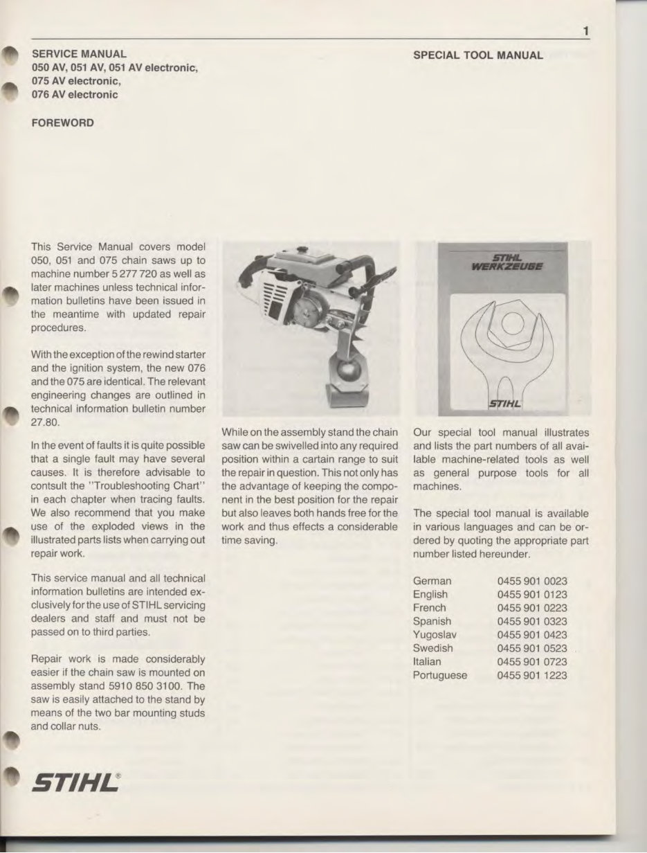
SERVICE MANUAL 050 AV, 051 AV, 051 AV electronic, 075 AV electronic, 076 AV electronic FOREWORD This Service Manual covers model 050, 051 and 075 chain saws up to machine number 5 277 720 as well as later machines unless technical infor- mation bulletins have been issued in the meantime with updated repair procedures. With the exception of the rewind starter and the ignition system, the new 076 and the 075 are identical. The relevant engineering changes are outlined in technical information bulletin number 27.80. In the event of faults it is quite possible that a single fault may have several causes. It is therefore advisable to contsult the " Troubleshooting Chart" in each chapter when tracing faults. We also recommend that you make use of the exploded views in the illustrated parts lists when carrying out repair work. This service manual and all technical information bulletins are intended ex- clusively for the use of STIHLservicing dealers and staff and must not be passed on to third parties. Repair work is made considerably easier if the chain saw is mounted on assembly stand 591 0 850 3100. The saw is easily attached to the stand by means of the two bar mounting studs and collar nuts. ST/HJ.: While on the assembly stand the chain saw can be swivelled into any required position within a cartain range to suit the repair in question. This not only has the advantage of keeping the compo- nent in the best position for the repair but also leaves both hands free for the work and thus effects a considerable time saving. 1 SPECIAL TOOL MANUAL Our special tool manual illustrates and lists the part numbers of all avai- lable machine-related tools as well as general purpose tools for all machines. The special tool manual is available in various languages and can be or- dered by quoting the appropriate part number listed hereunder. German 0455 901 0023 English 0455 901 0123 French 0455 901 0223 Spanish 0455 901 0323 Yugoslav 0455 901 0423 Swedish 0455 901 0523 Italian 0455 901 0723 Portuguese 0455 901 1223
3 8.4 P1ckup Hose/P1ckup Boay 58 8.5 Cover Plate/Worm 58 8.6 Disassembly and Repa1r of 011 Pump 58 8.7 Manual 011 Pump 60 8. 7.1 Construction and OperatiOn ot Manual 011 Pump 60 8.7.2 D1sassemb1y ana Repa1r 60 9. Decompression Valve 61 9.1 Construction ana Operat1on 61 10. Fuel System 62 10.1 ConstructiOn ana Operat1on of Carburetor 62 1 0.1.1 Operation of Fuel Pump 62 1 0.1 2 Operation ot Carburetor 62 10.2 Troubleshooting Chart 64 10.3 Leakage 1 est (Pressure Test) on Carburetor 66 1 0.4 Disassembly ot Carburetor 66 1 0.5 Repair of Carburetor 67 10.6 Carburetor AOJUStment 70 1 0 7 Fuel Lme ana lank Vent 70 1 0 8 A1r F1lter 71
4 1. SPECIFICATIONS 051 AV (050 AV), 075 AV, 076AV 1.1 Engine 1.2 Fuel System STIHL single cylinder two-stroke engine with specially processed cylinder bore Displacement: Cylinder bore: Stroke: Compression ratio. Power output: Max. torque: Max. permissible engine speed: Mean idle speed: Crankshaft: Crankshaft bearings: Crankpin: Big-end bearing: Piston pin: Small-end bearing: Rewind starter: Starter rope: Clutch: 051:89 cm 3 075; 076: 111 cm 3 051:52 mm 075; 076: 58 mm 42mm 9.5:1 051: 4.3 kW (5.8 DIN HP) at 7000 rpm 075; 076: 5.15 kW (7.0 DIN HP) at 7000 rpm 051: 5.9 Nm (0.6 kpm) at 5000 rpm 075; 076: 6.8 Nm (0.7 kpm) at 5000 rpm 10000 rpm 2000 rpm two-part drop forging 2 deep-groove ball bearings 18.0 mm dia. Needle cage 13.0 mm dia. Needle cage Friction shoe system with automatic starter rope rewind mechanism 4.5 mm dia., 1000 mm long Centrifugal clutch with press-fitted linings, 86 mm dia. Clutch engages at: approx. 2700 rpm Crankcase leakage test: with overpressure: with vacuum: Carburetor: Adjustment: High speed adjustment screw H: Low-speed adjustment screw L: Carburetor leakage test with overpressure: Fuel capacity: 0.6 bar (8.7 lbf/in 2 ) 0.4 bar (5.8 lbf/in 2 ) All position diaphragm carburetor with integral fuel pump Open 1 turn Open 1 1 /4 turns (basic setting with screws initially hard against their seats) 0.4 bar 051: 0.91itre
1.3 Ignition System Fuel mixture: Air filter 5 Regular grade gasoline and two-cycle engine oil. Mix ratio 1:40 with STIHL two-cycle engine oil; 1:25 with other branded two-cycle engine oils Flocked wire mesh element 051 AV (050 AV) up to machine No. 3 001 400 Type : Breaker-controlled magneto ignition Magneto edge gap : 12 -16 mm Air gap: Ignition timing : Ignition advance angle: Breaker point gap : Condenser : Ignition armature : 051 AVE, 075 AVE; 076 AVE Type: Air gap: Ignition timmg : Ignition advance angle: Ignition armature : Spark plug (suppressed): 051 : 075; 076: (9- 13mmuptomachineNo.2981245) 0.15- 0.3 mm 1.9-2.1 mm before T.D.C. (2.3 - 2.7 mm up to machine No. 2 981 245) 22° -23° before T.D.C. (24°- 26° before T.D.C. up to machine No. 2 981 245) 0.35 - 0.4mm Capacitance 0.6 - 0.9 ,_,F Coil winding resistance Primary Secondary approx. 1!1 approx. 8.7k0 Transistor-controlled (breakerless) magneto igniton 0.15-0.25 mm 2.5 mm before T.D.C. 25° before T.D.C. as 050/051 Bosch WSR 6 F (formerly WKA 200 TR 6) , Champion RCJ 6 Y or NGK BPM- 7, Heat range 175 Bosch WSR 6 F (formerly WKA 200 TR 6) , Champion RCJ 6 Y, Heat range 225, Electrode gap 0.5 mm, Spark plug thread M 14 x 1.25; 9.5 mm long
6 1.4 Tightening Torques Crankshaft nut-Ignition side M 8x1: Sprocket side M 12x1.51eft-hand: Clutch spider: Hub: Decompression valve or plug: M 6 hex. nuts : M 5 hex. nuts: M 5 socket head screws: M 5 pan head screws: M 4 pan head screws: Spark plug : Collar nuts: 1.5 Cutting Attachment Guide bars : Bar lengths: Oilomatic chain : Chain sprocket: Chain speed : Chain lubrication: Max. oil delivery rate: Min. oil delivery rate : Oil tank capacity: 35 Nm (3.5 kpm) 60 Nm (6.0 kpm) 40 Nm (4.0 kpm) 75 Nm (7.5 kpm) 12 Nm (1 .2 kpm) 8 Nm {0.8 kpm) 4 Nm (0.4 kpm) 8 Nm (0.8 kpm) 5 Nm (0.5 kpm) 2.5 Nm (0.25 kpm) 25 Nm (2.5 kpm) 25 Nm (2.5 kpm) STIHL Duromatic guide bars with stellite-tipped nose. STIHL Rollomatic guide bars with sprocket nose. Both types with corrosion-resistant finish and induction hardened rails. 051 : 43, 53, 63 and 75 em 075 : 43, 53, 63, 75 and 90 em 9.32 mm ( 3/ a" ) pitch 10.26 mm (0.404 " ) pitch 12 .7 mm ('12'' ) pitch a-tooth for 9.32 mm (3 /a") pitch 7-tooth for 10.26 mm (0.404" ) pitch 6-tooth for 12.7 mm ( 1 12 '') pitch 16.8 m/s at 8500 rpm with 0.404" chain Speed-controlled oil pump with pump plunger; operative only when chain is running. Additional flow quantity con- trol by means of adjusting screw. 075; 076 also equipped with unit-mounted manual oil pump. 19 cm 3 /min at 6000 rpm 7 cm 3 /min at 6000 rpm 0.551itre
1.6 Weights 1. 7 Special Accessories 7 Model Model Dry weight with 53 em bar and chain : 051 AVE 11 .2 kg 075 AVE; 076 AVE 11.7 kg STIHL repair kit 051 (050); 075: STIHL repair kit 051 ; 075; 076: Gasket set 051 (050): Gasket set 075; 076: Decompression valve for 051 : Rewind starter: 1111 900 5000 (With friction shoe) 1111 900 5001 (With pawl) 1111 007 1 050 1111 007 1 051 1111 020 9400
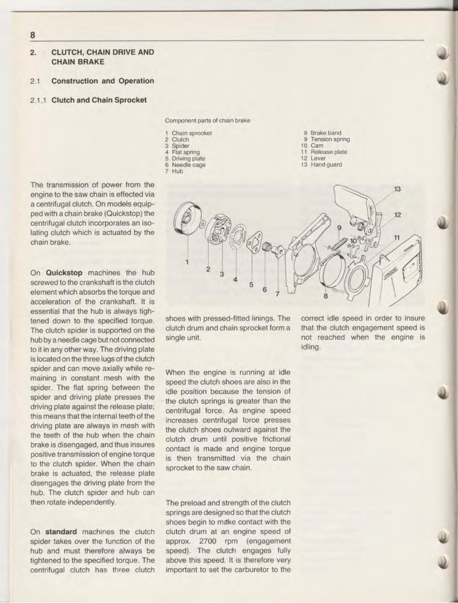
8 2. CLUTCH, CHAIN DRIVE AND CHAIN BRAKE 2.1 Construction and Operation 2.1 1 Clutch and Chain Sprocket The transmission of power from the engine to the saw chain is effected via a centrifugal clutch. On models equip- ped w1th a chain brake (Quickstep) the centrifugal clutch incorporates an iso- lating clutch which is actuated by the cham brake. On Ouickstop machines the hub screwed to the crankshaft is the clutch element which absorbs the torque and acceleration of the crankshaft It is essential that the hub is always tigh- tened down to the specified torque. The clutch spider is supported on the hub by a needle cage but not connected to it in any other way. The driving plate is located on the three lugs of the clutch spider and can move axially while re- maining in constant mesh with the spider. The flat spring between the spider and driving plate presses the driving plate against the release plate· this means that the intemal teeth of the driving plate are always in mesh with the teeth of the hub when the cha1n brake is disengaged, and thus insures positive transmission of engine torque to the clutch spider. When the chain brake is actuated, the release plate disengages the driving plate from the hub. The clutch spider and hub can then rotate independently. On standard machines the clutch spider takes over the function of the hub and must therefore always be tightened to the specified torque. The centrifugal clutch has three clutch Component parts of cha1n brake 1 Cha1n sprocket 2 Clutch 3 Spider 4 Flatspnng 5 Driving plate 6 Needle cage 7 Hub shoes with pressed-f1tted lin1ngs. The clutch drum and chain sprocket form a single unit When the engine is running at idle speed the clutch shoes are also in the idle position because the tension of the clutch springs is greater than the centrifugal force. As engine speed increases centrifugal force presses the clutch shoes outward against the clutch drum until positive frictional contact is made and engine torque is then transmitted via the chain sprocket to the saw chain. The preload and strength of the clutch springs are designed so that the clutch shoes begin to make contact with the clutch drum at an engine speed of approx. 2700 rpm (engagement speed). The clutch engages fully above this speed It is therefore very important to set the carburetor to the 8 Brake band 9 Tens1on spnng 10 Cam 11 Release plate 12 Lever 13 Hand guard correct idle speed in order to 1nsure that the clutch engagement speed 1s not reached when the engme is idling
You are purchasing a comprehensive Service & Shop manual for a Stihl 051 AV Electronic. This manual contains valuable technical information for both professional mechanics and DIY enthusiasts. With a file size of 179MB and 76 pages, this English manual provides detailed guidance on every aspect of your vehicle.
With hundreds of pages, this service manual covers a wide range of topics, including but not limited to:
Body and exterior
Electrical and electronic systems
Audio/Video devices
Charging system
Electrical supply system
Gauges and meters
Ignition system
Lighting and signaling systems
Sensors
Starting system
Switches
Wiring harnesses
Miscellaneous systems
Powertrain and chassis
Engine components and parts
Engine cooling system
Engine oil system
Exhaust system
Fuel supply system
Suspension and steering systems
Transmission system
Wheels and tire parts
This manual is equipped with numerous illustrations and easy-to-read text to assist you in your repair and maintenance tasks. It also includes a search function for easy navigation and the option to print specific pages as needed.
Rest assured, our service manuals are of excellent quality and are backed by great customer service. Whether you are a professional mechanic or a DIY enthusiast, this manual is an invaluable resource for maintaining and repairing your Stihl 051 AV Electronic.