

Stihl 026 Power Tool Service Manual
What's Included?
Fast Download Speeds
Online & Offline Access
Access PDF Contents & Bookmarks
Full Search Facility
Print one or all pages of your manual

STIHL 024, 026 2004-08
STIH)

1. Safety Precautions 1
2. Introduction 2
3. Specifications 3
3.1 Engine 3
3.2 Fuel System 3
3.3 Ignition System 4
3.4 Cutting Attachment 4
3.5 Special Accessories 4
3.5.1 For User 4
3.5.2 For Service 5
3.6 Tightening Torques 5
4. Clutch, Chain Drive,
Chain Brake and
Chain Tensioner 7
4.1 Clutch Drum and
Chain Sprocket 7
4.2 Clutch 8
4.3 Chain Brake 9
4.3.1 Checking Function 9
4.3.2 Disassembling 9
4.3.3 Assembling 11
4.3.4 Anchor Pin for
Brake Spring 13
4.3.5 Pin for Hand Guard 13
4.4 Front Chain
Tensioner (024) 14
4.5 Side Chain Tensioner 14
5. Engine 15
5.1 Muffler/Spark
Arresting Screen 15
5.2 Catalytic Converter 16
5.2.1 Construction and
Function 16
5.3 Leakage Test 17
5.3.1 Preparations 17
5.3.2 Pressure Test 18
5.3.3 Vacuum Test 18
5.4 Oil Seals 19
5.5 Exposing the Cylinder 21
5.6 Cylinder and Piston 21
5.6.1 Removing 21
5.6.2 Installing 22
5.7 Piston Rings 25
5.8 Crankcase 25
5.8.1 Removing the
Crankshaft 25
5.8.2 Installing the
Crankshaft 28
5.9 Decompression Valve 33
6. Ignition System 33
6.1 Spark Plug Boot/
Ignition Lead 33
6.2 Ignition Module 34
6.2.1 Ignition Timing 35
6.2.2 Removing and Installing 35
6.3 Short Circuit Wire/
Ground Wire 36
6.4 Wiring Harness 37
6.5 Contact Spring 38
6.6 Flywheel 38
7. Rewind Starter 39
7.1 General 39
7.2 Rewind Spring 39
7.2.1 Replacing 39
7.2.2 Tensioning 40
7.3 Starter Rope/Starter
Grip (ElastoStart) 41
8. AV Handle System 42
9. Master Control/
Handle System 43
9.1 Switch Shaft 43
9.2 Interlock Lever/
Throttle Trigger 43
10. Electric Handle
Heating System 45
10.1 Troubleshooting 45
10.1.1 Troubleshooting
Chart 46
10.1.2 Test Connections and
Test Values 47
10.2 Heater Switch 48
10.3 Heating Element in
Rear Handle 48
10.4 Heating Element in
Front Handle 49
10.5 Generator 50
11. Chain Lubrication 52
11.1 Pickup Body/
Suction Hose 52
11.2 Valve 53
11.3 Oil Pump 53
11.3.1 Servicing 55
12. Fuel System 55
12.1 Air Filter/Choke Shutter 55
12.2 Carburetor Preheating 56
12.3 Carburetor Heater 56
12.3.1 Construction and
Function 56
12.3.2 Testing 57
12.3.3 Troubleshooting
Chart 59
12.4 Printed Circuit Board 60
12.5 Carburetor 60
12.5.1 Leakage Testing 60
12.5.2 Removing and
Installing 61
12.5.3 Adjusting 63
12.6 Tank Vent 64
12.7 Fuel Hose 65
12.8 Tank Housing 65
13. Special Servicing
Tools and Aids 68
13.1 Special Servicing
Tools 68
13.2 Servicing Aids 70
1. SAFETY
PRECAUTIONS
If the engine is started up in the
course of repairs or maintenance
work, observe all local and country-
specific safety regulations as well
as the safety precautions and war-
nings in the owner’s manual.
Gasoline is an extremely flamm-
able fuel and can be explosive in
certain conditions.
Improper handling may result in
burns or other serious injuries.
Warning! Do not smoke or bring
any fire or flame near the fuel. All
work with fuel must be performed
outdoors only. Spilled fuel must be
wiped up immediately.
Wash hands thoroughly after
every contact with waste oil.
Do not pour waste oil down the
drain or allow it to soak into the
ground.
Collect waste oil and take it to an
official disposal site for environ-
ment-friendly disposal.
© 1999 Andreas Stihl AG & Co., Waiblingen
CONTENTS
024, 026 1
This service manual contains
detailed descriptions of all the
repair and servicing procedures
specific to this power tool series.
There are separate handbooks
for servicing procedures for
standardized parts and assem-
blies that are installed in several
STIHL power tool models.
Reference is made to these
handbooks in the appropriate
chapters of this manual.
As the design concept of model
024 and 026 chainsaws is almost
identical, the descriptions and
servicing procedures generally
apply to both. Differences are
described in detail.
Servicing procedures on the
carburetor are described in the
"Carburetors" handbook.
You should make use of the
illustrated parts lists while carrying
out repair work. They show the
installed positions of the individual
components and assemblies.
Refer to the latest edition of the
relevant parts list to check the part
numbers of any replacement parts
needed.
Parts lists on microfiche and CD-
ROM are always more up to date
than printed lists.
A fault on the machine may have
several causes. To help locate the
fault, consult the troubleshooting
charts for all assemblies in the
"Standard Repairs, Troubleshoot-
ing" handbook.
Refer to the "Technical Informa-
tion" bulletins for engineering
changes which have been intro-
duced since publication of this
service manual. Technical informa-
tion bulletins also supplement the
parts list until a revised edition is
issued.
The special servicing tools
mentioned in the descriptions are
listed in the last chapter of this ma-
nual.
Use the part numbers to identify
the tools in the "STIHL Special
Tools" manual.
The manual lists all special
servicing tools currently available
from STIHL.
Symbols are included in the text
and pictures for greater clarity.
The meanings are as follows:
In the descriptions:
• = Action to be taken as
shown in the illustration
(above the text)
- = Action to be taken that
is not shown in the
illustration
(above the text)
In the illustrations:
= Pointer
= Direction of movement
Service manuals and all technical
information bulletins describing
engineering changes are intended
exclusively for the use of STIHL
servicing dealers. They must not
be passed to third parties.
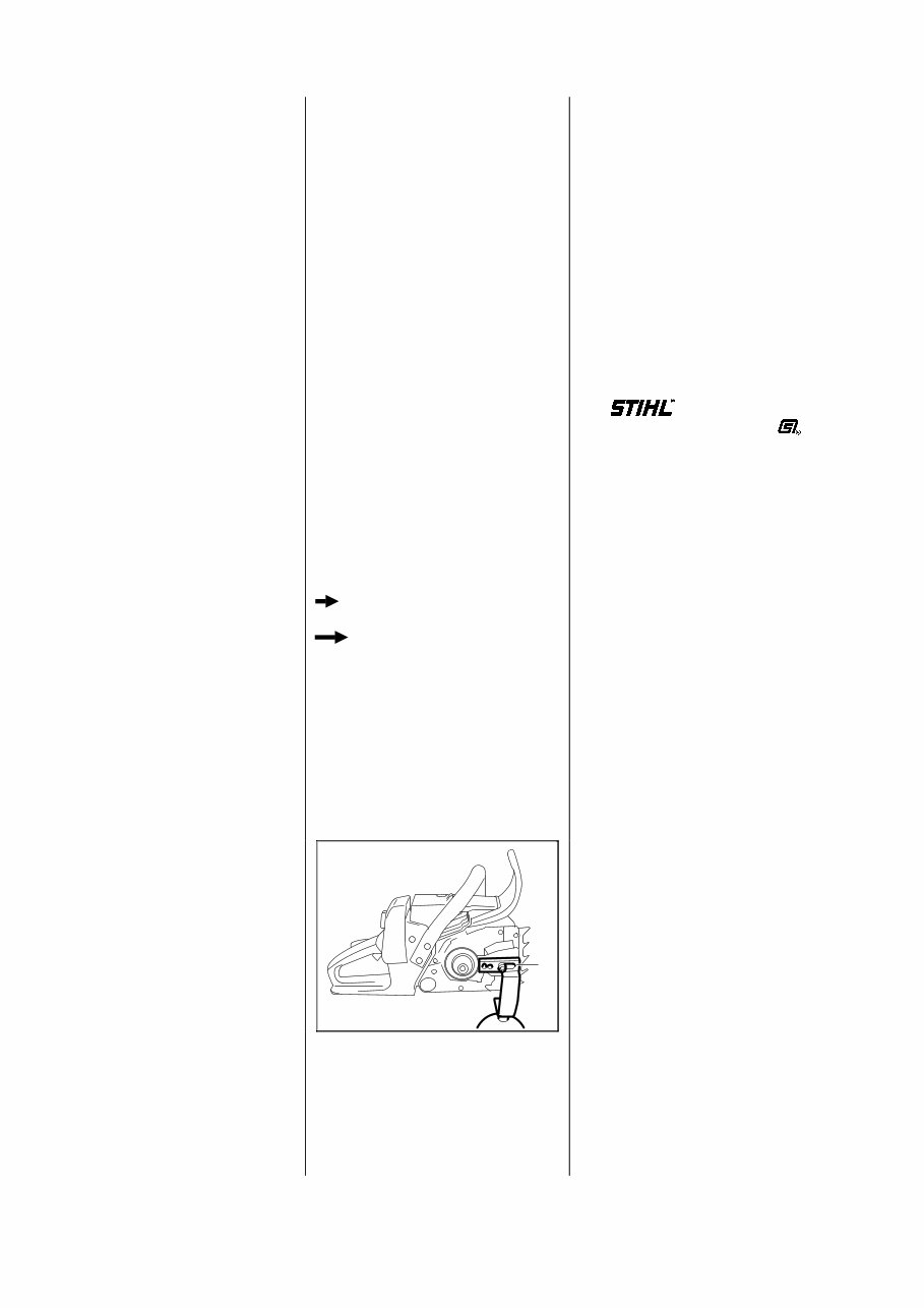
Servicing and repairs are made
considerably easier if the machine
is mounted on assembly stand (1)
5910 890 3100.
Remove the chain sprocket cover
and secure the machine to the
assembly stand with the sprocket
cover nuts. Machines with a quick
chain tensioning system and
secure with one M8 nut and
washer.
The complete unit can then be
swivelled to the best position for
the ongoing repair. This leaves
both hands free.
Always use original STIHL
replacement parts.
They can be identified by the
STIHL part number,
the logo
and the STIHL parts symbol
The symbol may appear alone on
small parts.
2. INTRODUCTION
VA 133RA001
1
2 024, 026

3.1 Engine
STIHL single-cylinder two-stroke engine with special impregnated cylinder bore
024 024 S 026
Displacement: 42 cm
3
(2.56 cu.in) 44.3 cm
3
(2.70 cu.in) 48.7 cm
3
(2.97 cu.in)
Bore: 42 mm (1.65 in) 42 mm (1.65 in) 44 mm (1.73 in)
Stroke: 30 mm (1.18 in) 32 mm (1.26 in) 32 mm (1.26 in)
Engine power to ISO 7293: 2.1 kW (2.85 bhp) 2.3 kW (3.1 bhp) 2.6 kW (3.5 bhp)
at 7,000 rpm at 7,000 rpm at 7,000 rpm
Max. permissible engine
speed with bar and chain: 13,000 rpm 13,000 rpm 14,000 rpm
Idle speed: 2,500 rpm
Bearings: Crankshaft supported in heavy-duty deep-groove ball bearings,
needle cages on small and big ends
Piston pin diameter: 10 mm (0.39 in)
Rewind starter: Single pawl system
Reserve pull on rope rotor: min. 1/2 turn
Starter rope: 3.5 mm (0.14 in) dia.
Clutch: Centrifugal clutch without linings
Clutch engages at: 3,600 rpm
Crankcase leakage
test
at gauge pressure: 0.5 bar (7.25 psi)
under vacuum: 0.5 bar (7.25 psi)
3.2 Fuel System
Carburetor: Diaphragm carburetor
Setting
High speed screw H: approx. 1 turn open
Low speed screw L: approx. 1 turn open
(standard setting)
Carburetor leakage test
at gauge pressure: 0.8 bar (11.6 psi)
Function of tank vent
at gauge pressure: ≤ 0.3 bar (4.35 psi)
under vacuum: * ≤ 0.05 bar (0.725 psi)
Fuel tank capacity: 0.47 L (16 fl.oz)
Octane number: min. 90 RON
Fuel mixture: Regular brand-name gasoline
and two-stroke engine oil
Mix ratio: 50:1 with STIHL 50:1 two-stroke engine oil
25:1 with other brand-name two-stroke, air-cooled engine oils
Air filter: Large area, bisectional flat filter,
additional prefilter in carburetor box cover
* Original tank vent
3. SPECIFICATIONS
024, 026 3

3.3 Ignition System Type: Electronic magneto ignition
(breakerless) with integral
trigger unit
Air gap: 0.2-0.3 mm (0.008-0.012 in)
Spark plug (suppressed): Bosch WSR 6F,
NGK BPMR 7 A or
Champion RCJ 6Y
Electrode gap: 0.5 mm (0.020 in)
3.4 Cutting Attachment Guide bars: STIHL Rollomatic
with nose sprocket,
corrosion-resistant finish and
induction hardened rails
Bar lengths: 32, 37 and 40 cm (13, 15, 18 in)
Oilomatic chain: 0.325" (8.25 mm) Rapid chain
Chain sprocket: 7-tooth 0.325"
Chain speed: 18.3 m/s (60 ft/s) at 9,500 rpm
Chain lubrication: Speed-controlled or adjustable
reciprocating pump
Oil feed rate
on non-adjustable pump: 6 cm
3
/min (0.2 fl.oz/min)
at 6,000 rpm
9.5 cm
3
/min (0.3 fl.oz/min)
at 10,000 rpm
on adjustable pump: 4.5-11.5 cm
3
/min
(0.15-0.4 fl.oz/min)
at 10,000 rpm
Oil tank capacity: 0.32 L (11 fl.oz)
3.5 Special Accessories
3.5.1 For User ElastoStart 0000 190 3401
Air filter, "fleece" 024 1121 120 1625
0.325", 8-tooth chain sprocket 1121 640 2001 1)
1121 640 2005 2)
Intake air preheating kit 024 1121 007 1030
Intake air preheating kit 026 1121 007 1027
(up to serial number X 30 976 774)
Intake air preheating kit 026 1121 007 1044
(from serial number X 30 976 775)
0.325", 7-tooth rim sprocket kit 1121 007 1001 1)
1121 007 1037 2)
0.325", 8-tooth rim sprocket kit 1121 007 1002 1)
1121 007 1038 2)
3/8" Picco, 7-tooth rim sprocket kit 1121 007 1004 1)
1121 007 1039 2)
3/8" Picco, 8-tooth rim sprocket kit 1121 007 1005 1)
1121 007 1040 2)
3/8", 7-tooth rim sprocket kit 1121 007 1035 1)
1121 007 1041 2)
Chain scabbard extension
(from 45 cm/18 in) 0000 792 9131
CAT mounting kit 1121 007 1042
1) 024
2) 026
4 024, 026

3.5.2 For Service Carburetor parts kit 024, small 1118 007 1060 (Tillotson)
Carburetor parts kit 024, large 1118 007 1065 (Tillotson)
Carburetor parts kit 024/026, large 1121 007 1062 (Walbro)
Carburetor parts kit 024/026, large 1118 007 1066 (Walbro WT 22)
Gasket set 024/026 1121 007 1050
3.6 Tightening Torques
Plastoform screws are used for polymer components. These screws form a permanent thread when they are
installed for the first time. They can be removed and installed as often as necessary without detrimentally
affecting the strength of the screwed assembly, providing the specified tightening torque is observed.
For this reason it is essential to use a torque wrench.
Fastener Thread For component Torque Remarks
size Nm lbf.ft
Pan head screw M4x8 Cover plate/chain tensioner 3.0 2.2
Countersunk screw PT4x12 Cover plate/chain sprocket
cover 2.5 1.8 1)
Collar screw M8x21.5 Bar mounting 23.0 17.0 2)
Collar screw M10/M8 Bar mounting 30.0 22.0 1) 3)
Spline screw IS-M4x12 Cover to crankcase,
sprocket side 3.0 2.2
M10x1 Decompression valve 14.0 10.3 4)
Self-tapping screw B4.2x9.5 Spark arresting screen 2.0 1.5
Spline screw M3.5x12 Generator 2.0 1.5 2)
Self-tapping screw IS-P6x19 Front handle top/bottom
(W version) 7.0 5.2
Self-tapping screw IS-P6x32.5 Front handle, top (polymer) 5.0 3.7
Self-tapping screw IS-P6x21.5 Front handle, bottom (polymer) 5.0 3.7
Self-tapping screw B3.9x19 Handle molding 1.6 1.2
Screw assembly IS-M4x16 Hand guard, left 4.0 3.0
Slotted nut M5 Shroud to cylinder 3.5 2.6
Self-tapping screw IS-P6x19 Chain catcher/plug 2.8 2.1
Spline screw IS-M5x12 Spiked bumper
(with self-locking nut) 7.5 5.5
Spline screw IS-M5x20 Crankcase 9.0 6.6
Mutter M5 Air filter 2.0 1.5
Spline screw IS-M4x16 Fan housing 4.0 3.0
M12x1L Clutch carrier 50.0 37.0
Self-tapping screw IS-P6x26.5 Annular buffer to tank
housing, left 5.0 3.7
Self-tapping screw IS-P6x19 Annular buffer to tank
housing, right 5.0 3.7
024, 026 5

Fastener Thread For component Torque Remarks
size Nm lbf.ft
Spline screw IS-M5x12 Annular buffer plate 8.0 5.9 2)
Spline screw IS-M5x16 Muffler to crankcase
(Cat version) 10.0 7.5 2)
Spline screw IS-M5x12 Muffler to crankcase
(non-Cat version) 10.0 7.5 2)
Spline screw IS-M5x12 Muffler to cylinder 10.0 7.5 2)
Spline screw IS-M5x12 Upper casing to muffler
(non-Cat version) 10.0 7.5
Spline screw IS-M5x16 Upper casing to muffler
(Cat version) 10.0 7.5
Nut M8x1 Flywheel 33.0 24.4
Spline screw M4x8 Side plate 3.0 2.2
Self-tapping screw BM4x16 Side plate 3.0 2.2 1)
Stud M5x8.5 Stud to cylinder, left 1.4 1.1 3)
Stud M5x8.5 Stud to cylinder, right 1.4 1.1
Nut M5 Carburetor 3.5 2.6
Spline screw IS-M5x20 Cylinder 10.5 7.7
M14x1.25 Spark plug 25.0 18.5
Spline screw IS-M5x20 Ignition module 7.0 5.2 2) 5)
Spline screw IS-M4x12 Oil pump 3.5 2.6
Use the following procedure when refitting a P screw in an existing thread:
– Place the P screw in the hole and rotate it counterclockwise until it drops down slightly.
– Tighten the screw clockwise to the specified torque.
This procedure ensures that the screw engages properly in the existing thread and does not form a new thread,
i.e. the thread is not weakened.
1) On machines with quick chain tensioner
2) Secure screw with Loctite 242.
3) Secure screw with Loctite 270.
4) On 026 only
5) A washer must be fitted under the screw head.
Note: Screws secured with adhesive (Loctite) are easier to release if they are heated with a hot air
blower (hair dryer). Take care on polymer components.
Power screwdriver setting for use in polymer: max. 600 rpm for Plastoform screws
6 024, 026
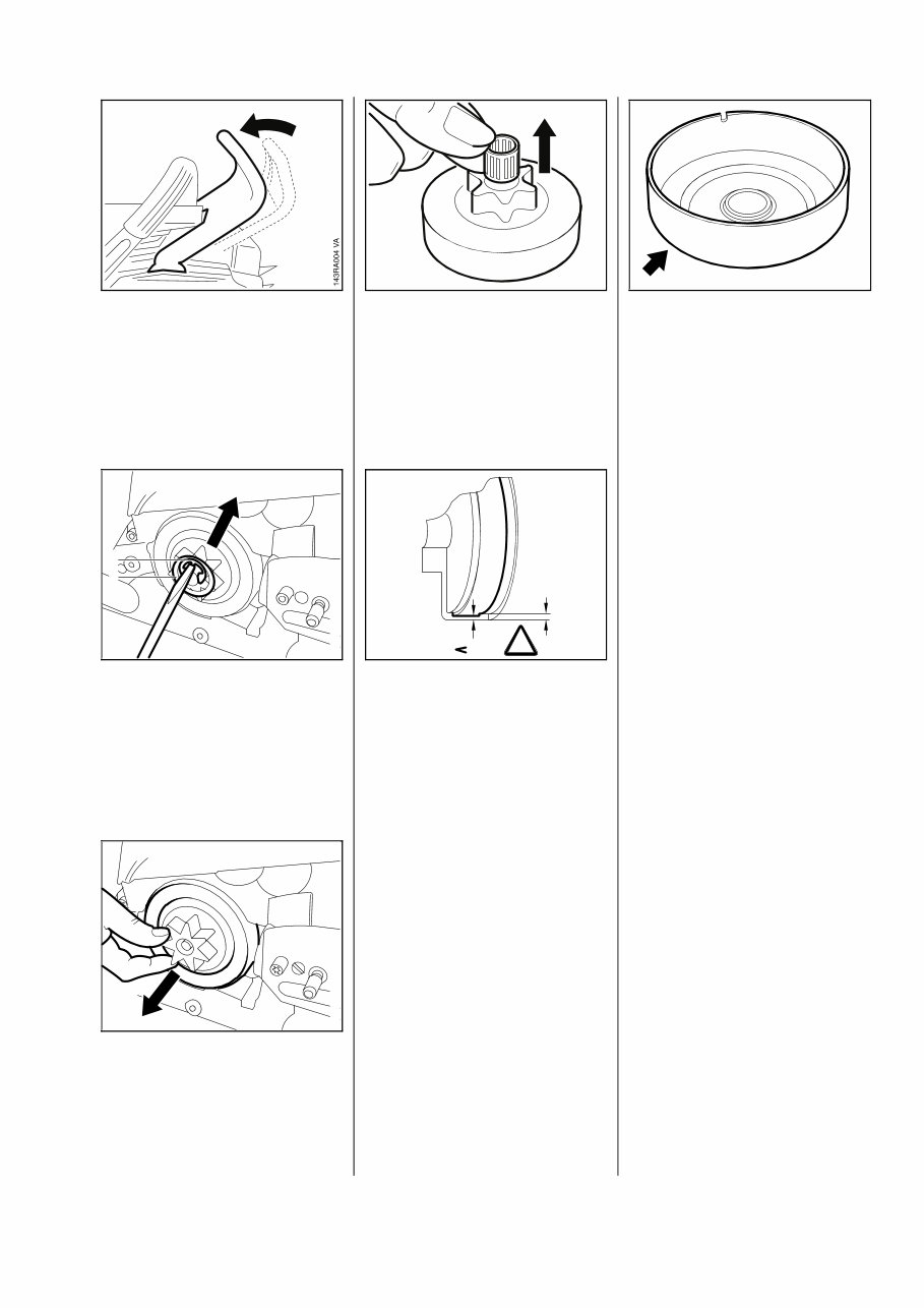
- Remove the chain sprocket
cover.
• Disengage the chain brake by
pulling the hand guard toward
the front handle.
• Remove the E-clip (1).
• Remove the washer (2).
- If a rim sprocket is fitted, pull
it off.
• Pull off the clutch drum/chain
sprocket.
• Remove the needle cage.
- Clean and inspect the clutch
drum/chain sprocket.
Important: If there are noticeable
wear marks on the inside diameter
of the clutch drum, check its wall
thickness. If it is less than 80% of
the original wall thickness, fit a
new clutch drum.
Note: If the clutch drum has to be
replaced, also check the brake
band - see 4.3.2.
• If the clutch drum is still service-
able, use No. 120 emery paper
or emery cloth (grain size
approx. 120µm) to clean and
roughen its friction surface.
Reassemble in the reverse
sequence.
- Clean stub of crankshaft.
Wash needle cage in clean white
spirit and lubricate with grease -
see 13.2.
- Replace damaged needle cage.
- On 026, rotate clutch drum/chain
sprocket and apply slight
pressure at the same time
until driver on oil pump worm
engages the notch on the drum’s
circumference.
- If machine is equipped with a
rim sprocket, refit it so that the
cavities face outwards.
4. CLUTCH, CHAIN DRIVE, CHAIN BRAKE AND CHAIN TENSIONER
4.1 Clutch Drum and Chain Sprocket
VA
143RA007
VA 170RA005
VA 133RA002
1
2
80%
100%
145RA006
!
VA
VA 133RA003
024, 026 7
Troubleshooting chart - see
"Standard Repairs, Trouble-
shooting" handbook.
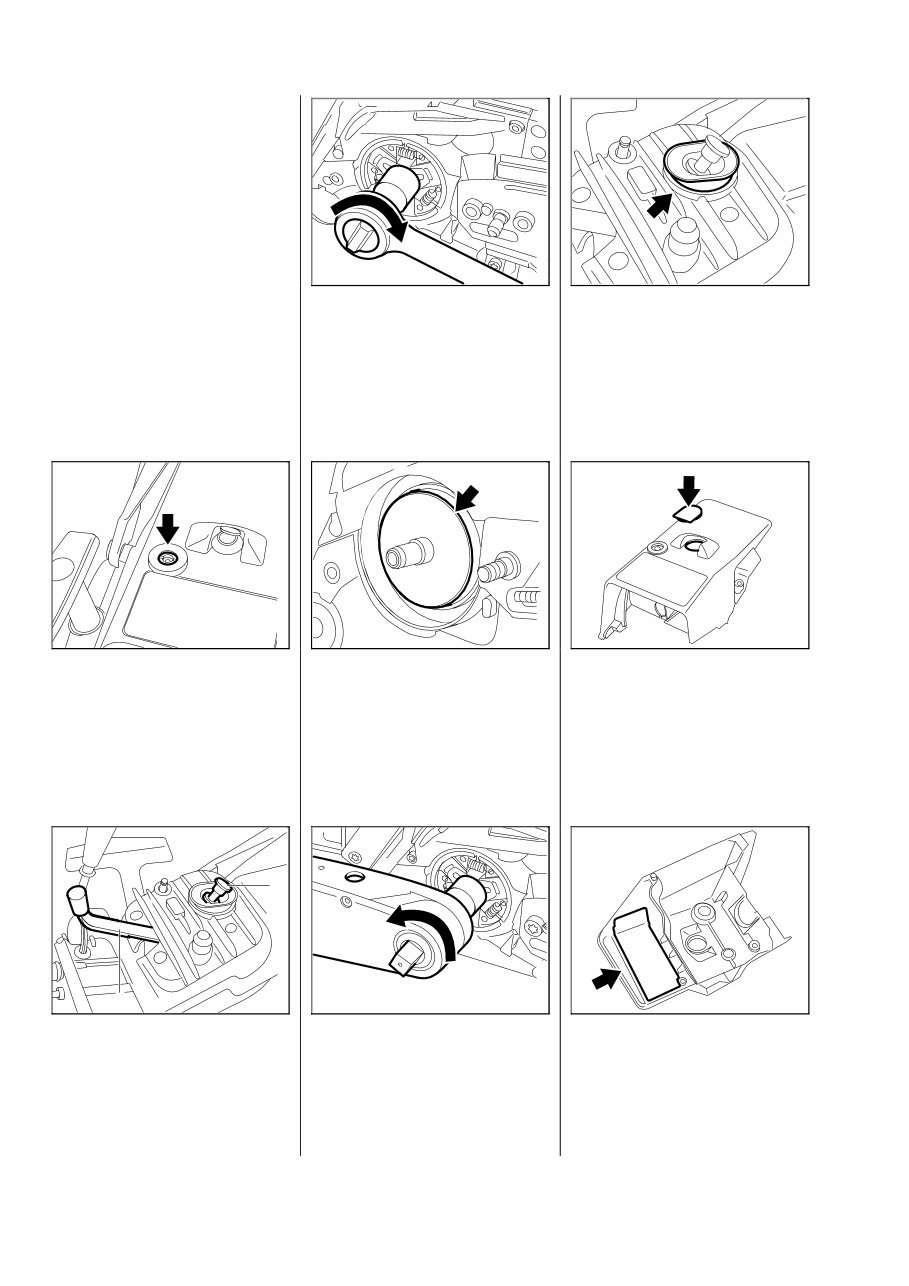
- Remove the clutch drum/chain
sprocket - see 4.1.
- Remove the air filter - see 12.1.
• Unscrew slotted nut from the
shroud.
- Remove the shroud.
- Pull off the spark plug boot.
- Unscrew the spark plug.
• Close the decompression
valve (1), where fitted.
• Push the locking strip (2)
0000 893 5903 into the cylinder.
• Unscrew the clutch in the
direction of the arrow (left-hand
thread).
- Disassemble and reassemble
the clutch - see "Standard
Repairs, Troubleshooting"
handbook.
• On 024, if a cover washer is
fitted behind the original clutch,
do not refit it when installing the
new clutch.
• Screw clutch onto crankshaft
and torque down to 50 Nm
(37 lbf.ft).
- Remove locking strip from
cylinder.
- Install spark plug and torque
down to 25 Nm (18.5 lbf.ft).
• On machines with a decompres-
sion valve, make sure the cover
is properly seated.
• If the shroud is replaced on a
026 machine without decompres-
sion valve, seal the opening in
the shroud with the cap.
• Check condition of heat shield
(foil) and fit a new one if
necessary.
- Fit the shroud.
4.2 Clutch
VA 133RA007
VA 133RA010
VA 133RA004
VA 133RA008
VA 133RA035
VA 133RA006
2
1
VA 133RA009
VA 133RA005
8 024, 026
The chain brake is one of the most
important safety devices on the
chain saw. Its efficiency is measu-
red in terms of braking time, i.e.
the time that elapses between
activating the brake and the saw
chain coming to a standstill. The
shorter the braking time, the better
the efficiency and protection
offered.
Contamination (with chain oil,
chips, fine particles of abrasion,
etc.) and smoothing of the friction
surfaces of the brake band and
clutch drum impair the coefficient
of friction. This, in turn, reduces
the frictional forces and thus pro-
longs the braking time. A fatigued
or stretched brake spring has the
same negative effect.
- Start the engine.
- With the chain brake activated
(locked), open throttle wide for
brief period (max. 3 seconds) -
the chain must not rotate.
- With the chain brake released,
open throttle wide and activate
the brake manually - the chain
must come to an abrupt
stop.
Note: The braking time is in
order if deceleration of the
saw chain is imperceptible to
the eye.
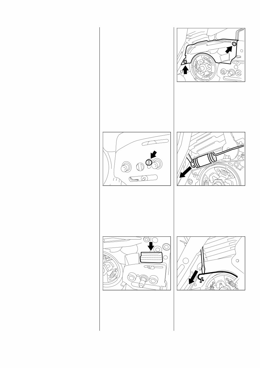
- Remove clutch drum/chain sprok-
ket - see 4.1.
- Relieve tension of brake spring
by pushing hand guard forwards.
• Take out the screw.
- Remove the side plate.
• On 026, remove the upper
bumper strip from the chain
tensioner.
• Take out the screws.
- Remove the cover.
• Carefully pry the brake spring
off the anchor pin and unhook it
from the bell crank.
• Lever the brake band out of the
crankcase.
- Unhook the brake band from the
bell crank.
4.3 Chain Brake
4.3.1 Checking Function 4.3.2 Disassembling
VA 133RA013 VA 133RA014
VA 133RA011
VA 133RA012
133RA015 VA
024, 026 9
You're Reading a Preview
What's Included?
Fast Download Speeds
Online & Offline Access
Access PDF Contents & Bookmarks
Full Search Facility
Print one or all pages of your manual
$31.99
$41.99
Viewed 63 Times Today


Secure transaction
What's Included?
Fast Download Speeds
Online & Offline Access
Access PDF Contents & Bookmarks
Full Search Facility
Print one or all pages of your manual
$31.99
$41.99
You are purchasing a Service & Shop manual for a Stihl 026. This comprehensive manual is essential for both professional mechanics and DIY enthusiasts. It contains hundreds of pages with detailed instructions, accompanied by numerous illustrations, covering a wide range of topics including:
- Body and exterior
- Electrical and electronic
- Audio/Video devices
- Charging system
- Electrical supply system
- Gauges and meters
- Ignition system
- Lighting and signaling systems
- Sensors
- Starting system
- Switches
- Wiring harnesses
- Miscellaneous
- Powertrain and chassis
- Engine components and parts
- Engine cooling system
- Engine oil system
- Exhaust system
- Fuel supply system
- Fuel Suspension and steering systems
- Transmission system
- Wheels and tire parts
This manual is an invaluable resource, equipped with a search function for easy navigation and the option to print specific pages. Rest assured of its excellent quality and our commitment to providing great customer service. Model: Stihl 026


