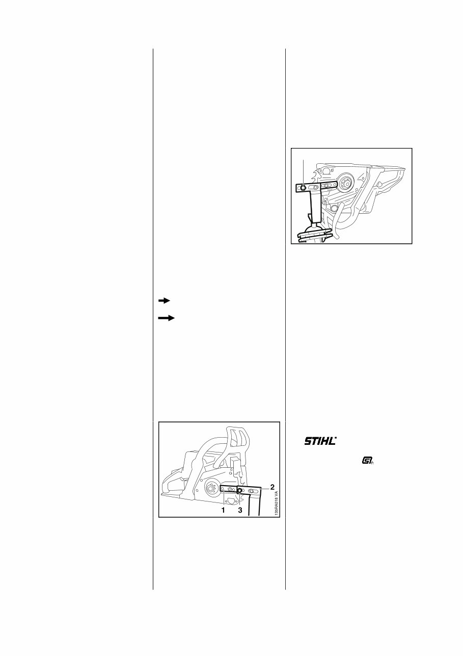
Online version - not for reprint This service manual contains detailed descriptions of all the repair and servicing procedures specific to this power tool series. There are separate handbooks for servicing procedures for standardized parts and assemblies that are installed in several STIHL power tool models. Reference is made to these handbooks in the appropriate chapters in this manual. As the design concept of model 021, 023 and 025 chainsaws is almost identical, the descriptions and servicing procedures in this manual generally apply to all three models. Differences are described in detail. You should make use of the illustrated parts lists while carrying out repair work. They show the installed positions of the individual components and assemblies. Refer to the latest edition of the relevant parts list to check the part numbers of any replacement parts needed. Parts lists on microfiche and CD-ROM are always more up to date than printed lists. A fault on the machine may have several causes. To help locate the fault, consult the troubleshooting charts for all assemblies in the "Standard Repairs, Troubleshoo- ting" handbook. Refer to the "Technical Informa- tion" bulletins for engineering changes which have been intro- duced since publication of this service manual. Technical informa- tion bulletins also supplement the parts list until a revised edition is issued. The special servicing tools mentio- ned in the descriptions are listed in the last chapter of this manual. Use the part numbers to identify the tools in the "STIHL Special Tools" manual. The manual lists all special servicing tools currently available from STIHL. Symbols are included in the text and pictures for greater clarity. The meanings are as follows: In the descriptions: • = Action to be taken as shown in the illustration (above the text) -= Action to be taken that is not shown in the illustration (above the text) In the illustrations: = Pointer = Direction of movement Service manuals and all technical information bulletins describing engineering changes are intended exclusively for the use of STIHL servicing dealers. They must not be passed to third parties. Servicing and repairs are made considerably easier if the clamp (1) 5910 890 2000 is used to mount the machine on assembly stand (2) 5910 890 3100 so that one clamp screw engages the outer 10 mm bore (3) in the assembly stand. To service the underside of the machine (e.g. remove the oil pump), turn the machine through 180 degrees and mount it so that one clamp screw engages the inner 10 mm bore (1) in the assembly stand. Note: Pull the hand guard back against the front handle for this purpose. The powerhead can then be swivelled to the best position for the ongoing repair and this leaves both hands free. Always use original STIHL replacement parts. They can be identified by the STIHL part number, the logo and the STIHL parts symbol The symbol may appear alone on small parts. 2. INTRODUCTION VA 135RA019 1 2 021, 023, 025
Online version - not for reprint 3.1 Engine STIHL single cylinder two-stroke engine with special impregnated cylinder bore 021 023 L 023 025 Displacement: 35.2 cm 3 40.2 cm 3 40.2 cm 3 45.4 cm 3 2.15 cu.in 2.45 cu.in 2.45 cu.in 1.8 cu.in Bore: 40 mm 40 mm 40 mm 42 m 42,5 mm 1.57 in 1.57 in 1.57 in 1.7 in Stroke: 28 mm 32 mm 32 mm 32 mm 32 mm 1.10 in 1.26 in 1.26 in 1.26 in Power output to ISO 7293: 1.5 kW (2.0 bhp) 1.1 kW (1.5 bhp) 1.9 kW (2.6 bhp) 2.2 kW (3.0 bhp) at 9,000 rpm at 6,500 rpm at 9,500 rpm at 10,000 rpm Max. permissible engine speed (with bar and chain): 11,500 rpm 1) 12,500 rpm 13,000 rpm Idle speed: 2,800 rpm Bearings: Crankshaft supported in heavy-duty ball bearings, needle cages on small and big ends Cylindrical rollers on big end 2) Piston pin diameter: 10 mm (0.39 in) Rewind starter: Pawl engagement Pawls: Single pawl system Reserve pull on rope rotor: min. 1/2 turn Starter rope: 3.0 mm (0.12 in) dia. Clutch: Centrifugal clutch without linings Clutch engages at: 3,600 rpm 4,100 rpm 3,500 rpm 3,500 rpm Crankcase leakage test at gauge pressure: 0.5 bar (7.25 psi) under vacuum: 0.5 bar (7.25 psi) 3.2 Fuel System Carburetor: Diaphragm carburetor Standard setting on carburetors with three adjusting screws High speed screw H: Open approx. 1 turn Low speed screw L: Open approx. 1 turn Carburetor leakage test at gauge pressure: 0.8 bar (11.6 psi) Function of tank vent at gauge pressure: ≤ 0.3 bar (4.35 psi) under vacuum: ≤ 0.05 bar (0.725 psi) Fuel tank capacity: 0.47 l (1 US pt) Octane rating: min. 90 RON (US/CAN; pump octane min. 87) Fuel mixture: Regular brand name gasoline and two-stroke engine oil Mix ratio: 50:1 with STIHL two-stroke engine oil 25:1 with other brand name two-stroke, air-cooled engine oils Air filter:Box filter, fabric or fleece filter 1) Not adjustable 2) 021 only up to serial number X 34 944 402 3. SPECIFICATIONS 021, 023, 025 3
Online version - not for reprint 3.3 Ignition System Type: Electronic magneto ignition (breakerless) with integral trigger unit Air gap: 0.2 - 0.4 mm (0.008 - 0.016 in) Spark plug (suppressed): Bosch WSR 6F, NGK BPMR 7 A, Champion RCJ 6Y or Autolite 2984 Electrode gap: 0.5 mm (0.020 in) 3.4 Cutting Attachment Chain lubrication: Fully automatic speed-controlled oil pump with rotary piston Oil deivery rate: approx. 7.5 cm 3 /min (0.25 fl.oz/min) at 10,000 rpm Oil tank capacity: 0.20 l (0.4 US pt) 3.5 Special Accessories 3.5.1 For User STIHL repair kit 1123 900 5000 3/8" P, 8-tooth rim sprocket kit 1123 007 1001 .325", 7-tooth rim sprocket kit 1123 007 1003 .325", 8-tooth rim sprocket kit 1123 007 1002 1/4", 8-tooth spur sprocket 1123 640 2010 3/8" P, 7-tooth spur sprocket 1123 640 2000 .325", 7-tooth spur sprocket 1123 640 2015 .325", 8-tooth spur sprocket 1123 640 2020 Side chain tensioner kit 1123 007 1000 3.5.2 For Service Carburetor parts kit 1123 007 1061 4 021, 023, 025
Online version - not for reprint DG screws are used in the polymer and light-alloy components. These screws form a permanent thread when they are installed for the first time. They can be removed and installed as often as necessary without detrimentally affecting the strength of the screwed assembly, providing the specified tightening torque is observed. For this reason it is essential to use a torque wrench. Fastener Thread For component Torque Remarks size Nm lbf.ft Spline screw IS-DG4x15 Chain brake cover 2.0 1.5 Spline screw IS-DG4x15 Handle molding 1.6 1.2 Spline screw IS-DG4x15 Connector 2.5 1.8 (engine/oil pump) Spline screw IS-DG4x15 Ground wire 3.5 2.6 (to cylinder) Spline screw IS-DG5x24 Handle housing/ 3.5 2.6 front handle Spline screw IS-DG5x24 Hand guard 3.5 2.6 Spline screw IS-DG5x24 Hand guard 3.7 2.8 1) Spline screw IS-DG5x24 Fan housing 3.5 2.6 Spline screw IS-DG5x24 Buffer (to front handle) 3.5 2.6 Spline screw IS-DG5x24 Buffer (to engine) 3.5 2.6 Spline screw IS-DG5x24 Ignition module 4.0 3.0 (to engine housing) Spline screw IS-DG5.3x40 Cylinder 9.5 7.0 (to engine housing) Collar screw DG8x18 Guide bar mounting 16.0 11.8 Collar screw (rear) DG8x18 Guide bar mounting 8.0 5.9 3) M12x1L Carrier (clutch) 50.0 37.0 M14x1.25 Spark plug 25.0 18.5 Hexagon nut M5 Muffler 7.0 5.2 Hexagon nut M5 Filter housing/carburetor 2.7 2.0 Collar nut M8x1 Flywheel to crankshaft 28.0 21.0 M12x1.5 Decompression valve 14.0 10.3 2) Slotted nut M5 Filter base/carburetor 2.0 1.5 1) Spline screw IS-DG5x16 Spiked bumper 3.7 2.8 Use the following procedure to fit a DG screw in an existing thread: – Place the DG screw in the hole and rotate it counterclockwise until drops down slightly. – Tighten the screw clockwise to the specified torque. This procedure ensures that the screw engages properly in the existing thread and does not form a new thread, which would weaken the assembly. 1) 023 L 2) On easy start version only 3) With quick chain adjuster Note: Power screwdriver speed settings for polymer: Plastoform screws max. 600 rpm DG screws max. 500 rpm 3.6 Tightening Torques 021, 023, 025 5
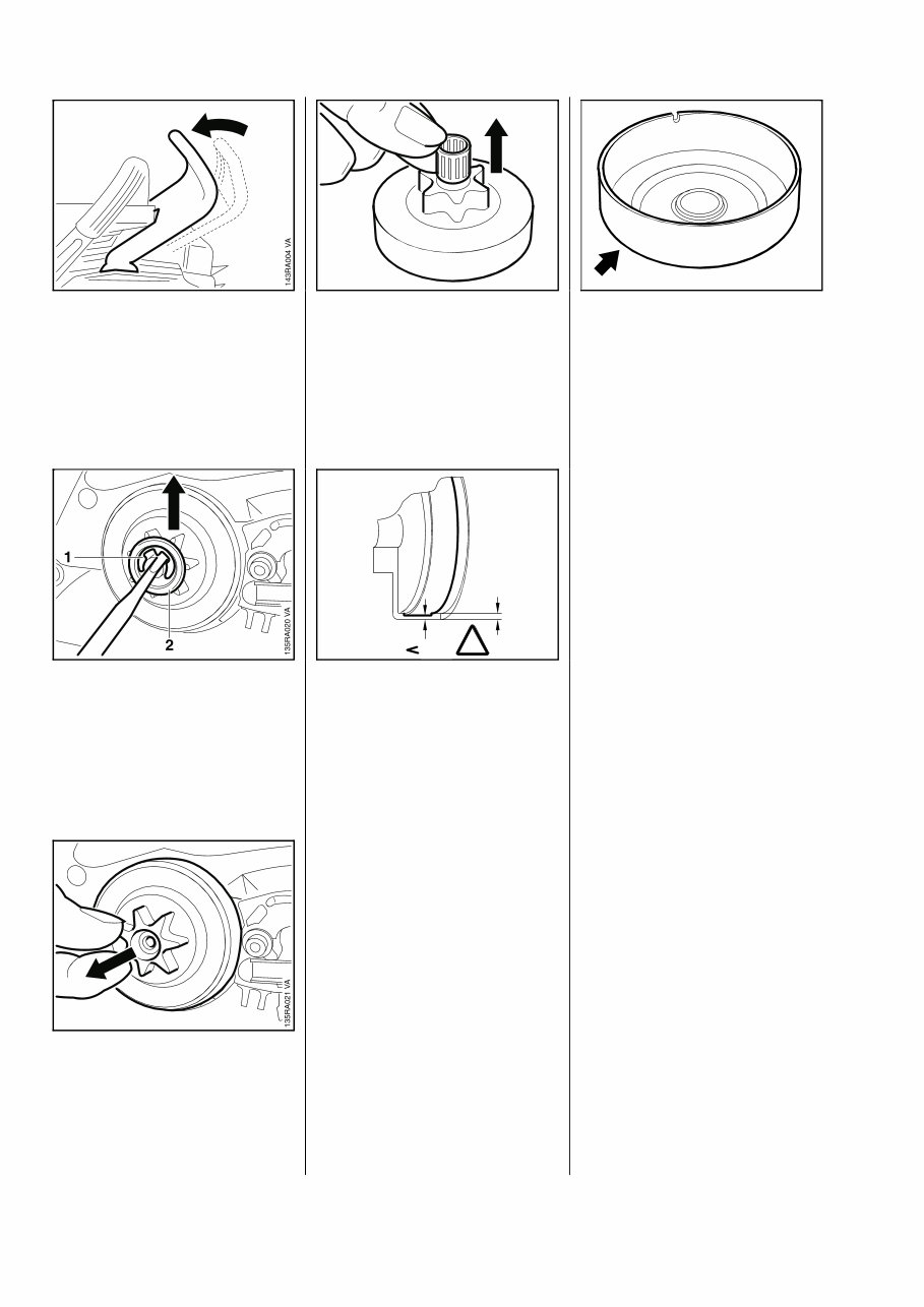
Online version - not for reprint - Remove the chain sprocket cover. • Disengage the chain brake by pulling the hand guard toward the front handle. • Remove the E-clip (1). • Remove the washer (2). - Remove the rim sprocket, if fitted. • Pull off the clutch drum/chain sprocket. • Take the needle cage out of the sprocket. - Clean and inspect the clutch drum/chain sprocket. Important: If there are noticeable wear marks on the inside diameter of the clutch drum, check its wall thickness. If it is less than 80% of the original wall thickness, fit a new clutch drum. Note: If the clutch drum has to be replaced, also check the brake band - see 4.4.2. • If the clutch drum/chain sprocket is still serviceable, use No. 120 emery paper or emery cloth (grain size approx. 120μm) to clean and roughen its friction surface. Reassemble in the reverse sequence. - Clean stub of crankshaft. Wash needle cage in clean white spirit and lubricate with grease - see 11.2. - Replace damaged needle cage. - Rotate clutch drum/chain sprocket and apply slight pressure at the same same until oil pump drive spring engages properly. - If rim sprocket was fitted, re- install it with the cavities facing outward. 4. CLUTCH, CHAIN DRIVE, CHAIN BRAKE, CHAIN TENSIONER 4.1 Clutch Drum/Chain Sprocket VA 143RA007 VA 170RA005 80% 100% 145RA006 ! VA 6 021, 023, 025
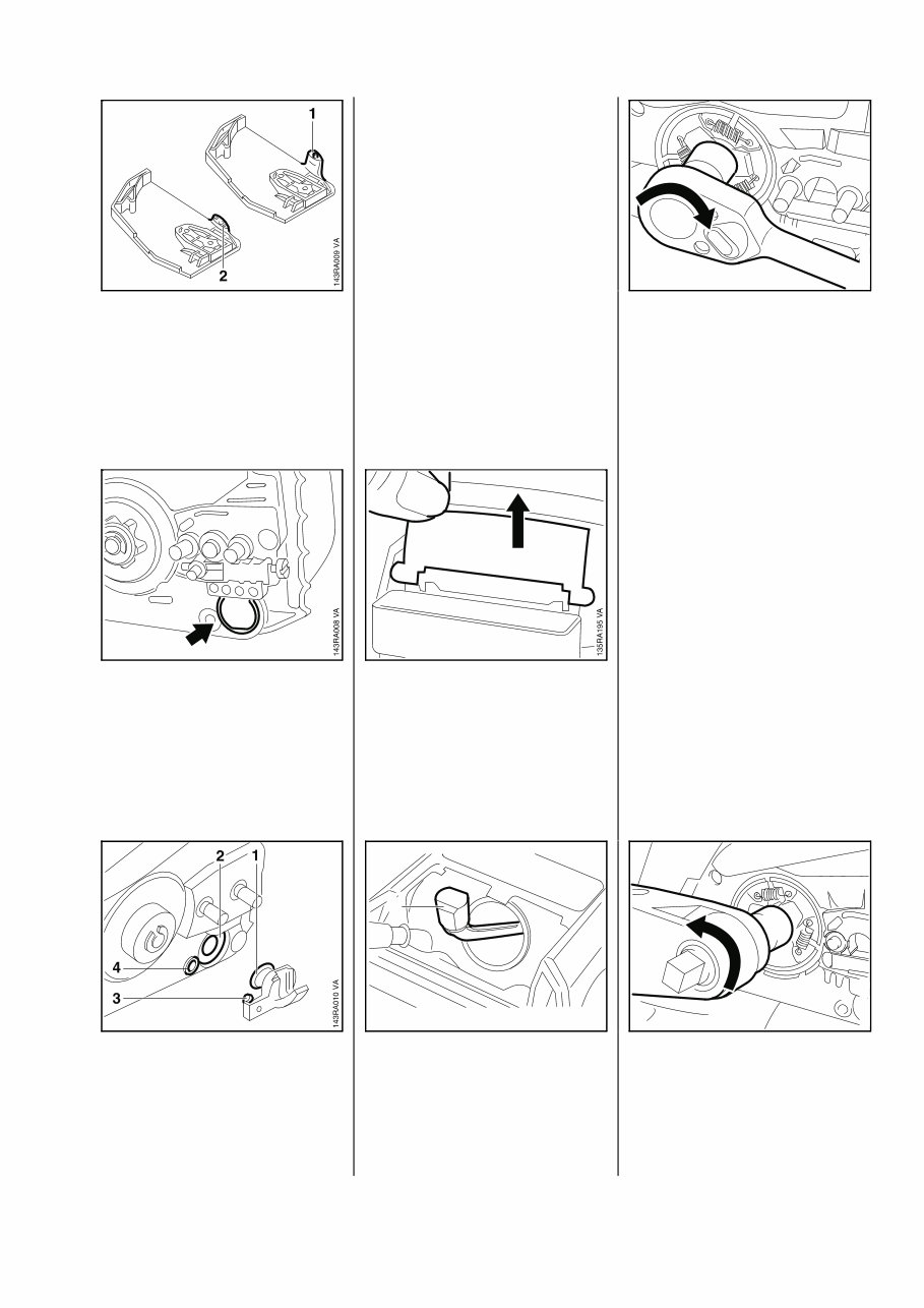
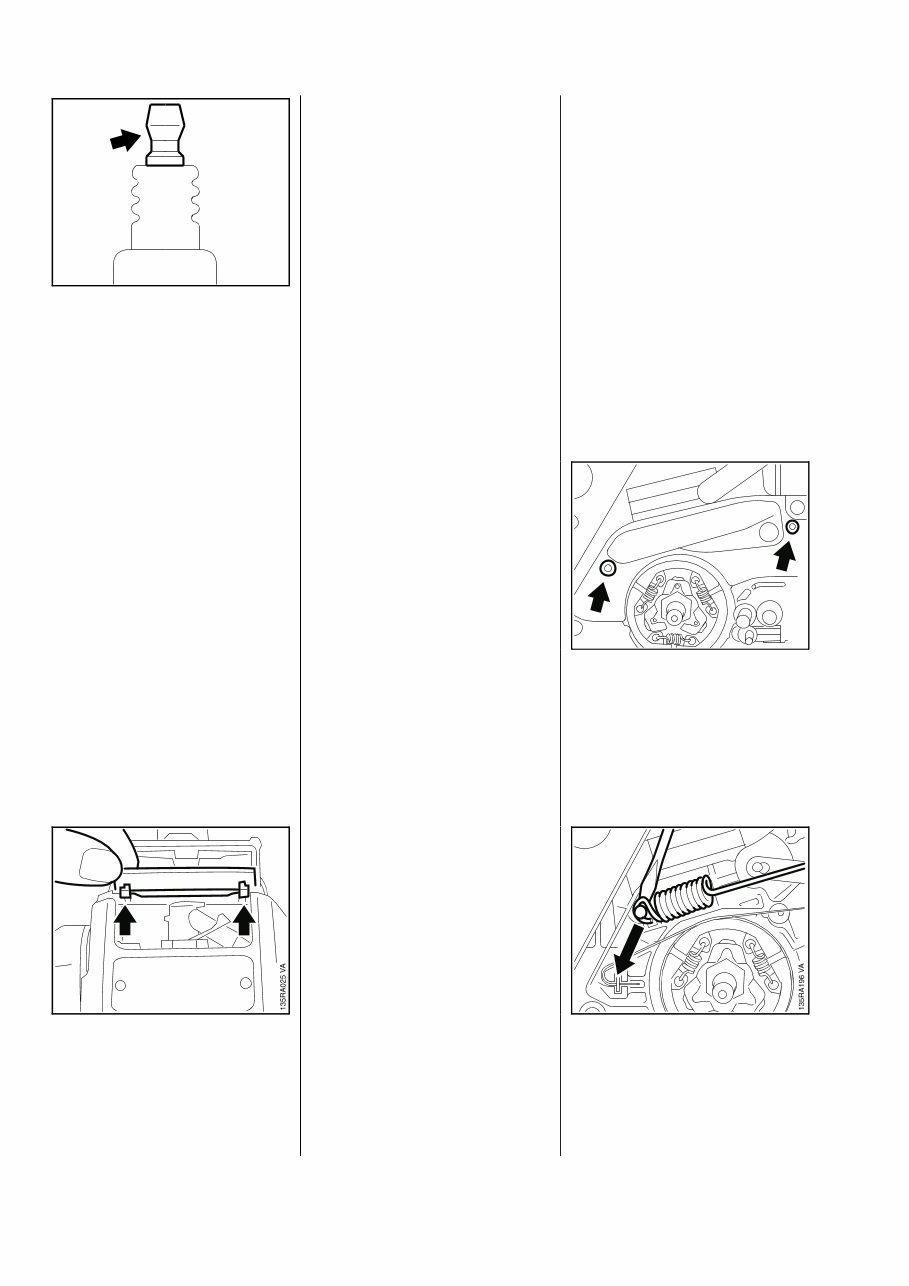
Online version - not for reprint Sprocket cover with integrally molded chain catcher (1). If the chain catcher has broken off (2), repair as follows: • Pry the plug out of the front right- hand AV element. • Oil the cylindrical part (1) of the replacement chain catcher. • Push the chain catcher into the AV element (2) and engage the peg (3) in the housing bore (4) at the same time. Troubleshooting chart - see "Standard Repairs, Trouble- shooting" handbook. - Remove the clutch drum/chain sprocket - see 4.1. - Remove the air filter - see 10.1. - On 023 L, remove the filter base - see 10.2.2. • Take out the shutter. - Pull boot off the spark plug and then unscrew the spark plug. - Close the decompression valve, if fitted. • Push the locking strip (1) 0000 893 5903 into the cylinder. • Unscrew clutch from the crankshaft clockwise (left-hand thread). - Service the clutch - see "Standard Repairs, Trouble-shooting" handbook. • Screw on the clutch and tighten down to 50 Nm (37 lbf.ft). - Install the clutch drum/chain sprocket - see 4.1. 4.2 Chain Catcher 4.3 Clutch VA 135RA023 VA 135RA022 1 VA 135RA024 021, 023, 025 7
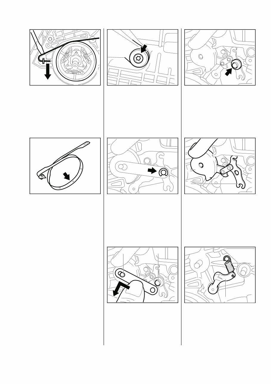
Online version - not for reprint - Remove locking strip from cylinder. - Insert spark plug and tighten down to 25 Nm (18.5 lbf.ft). • If spark plug has a separate terminal nut, make sure it is properly tightened down. - Fit boot on the spark plug. • Fit the shutter so that its lugs engage the recesses in the handle housing. - Install the air filter - see 10.1. The chain brake is one of the most important safety devices on the chainsaw. Its efficiency is measured in terms of the chain braking time, i.e. the time that elapses between activating the brake and the saw chain coming to a complete standstill. The shorter the braking time, the better the efficiency and protection offered against being injured by the rotating chain. Contamination (with chain oil, chips, fine particles of abrasion, etc.) and smoothing of the friction surfaces of the brake band and clutch drum impair the coefficient of friction. This, in turn, reduces the frictional forces and thus prolongs the braking time. A fatigued or stretched brake spring has the same negative effect. - Start the engine. - With the chain brake activated (locked), open throttle wide for a brief period (max. 3 seconds) - the chain must not rotate. - With the chain brake released, open throttle wide and activate the brake manually - the chain must come to an abrupt stop. Note: The braking time is in order if deceleration of the saw chain is imperceptible to the eye. - Remove the clutch drum/chain sprocket - see 4.1. - Release brake spring tension by pushing hand guard forward. - Remove upper bumper strip from tensioner. • Take out the screws. - Remove the cover. • Carefully ease the brake spring off the anchor pin and take it off the bell crank. 4.4 Chain Brake 4.4.1 Checking Function 4.4.2 Disassembly 250RA008 VA VA 135RA026 8 021, 023, 025
Online version - not for reprint • Pry the brake band out of the engine housing. - Disconnect brake band from bell crank. Replace the brake band if: - there are noticeable signs of wear (large areas on inside diameter and/or parts of outside diameter) and - its remaining thickness is < 0.6 mm (0.024"). Important! Thickness of brake band must not be less at any point. • If the brake band is still serviceable, use No. 120 emery paper or emery cloth (grain size approx. 120μm) to clean and roughen its entire friction surface (inside diameter). • Take out the screw. • Remove the E-clip. • Remove strap from bell crank pivot pin (1). • Push the strap sideways and lift it off the hand guard pivot pin (2). • Remove the washer. • Carefully pry the hand guard (1) and bell crank (2) off their pivot pins and lift away together. - Pull the bell crank out of the hand guard. • Up to serial number X 28 310 254, remove the spring (1). • Pull out the cam lever (2). VA 135RA027 VA 170RA014 VA 135RA028 VA 135RA029 VA 135RA030 2 1 VA 135RA031 135RA032 1 2 VA VA 135RA033 1 2 021, 023, 025 9
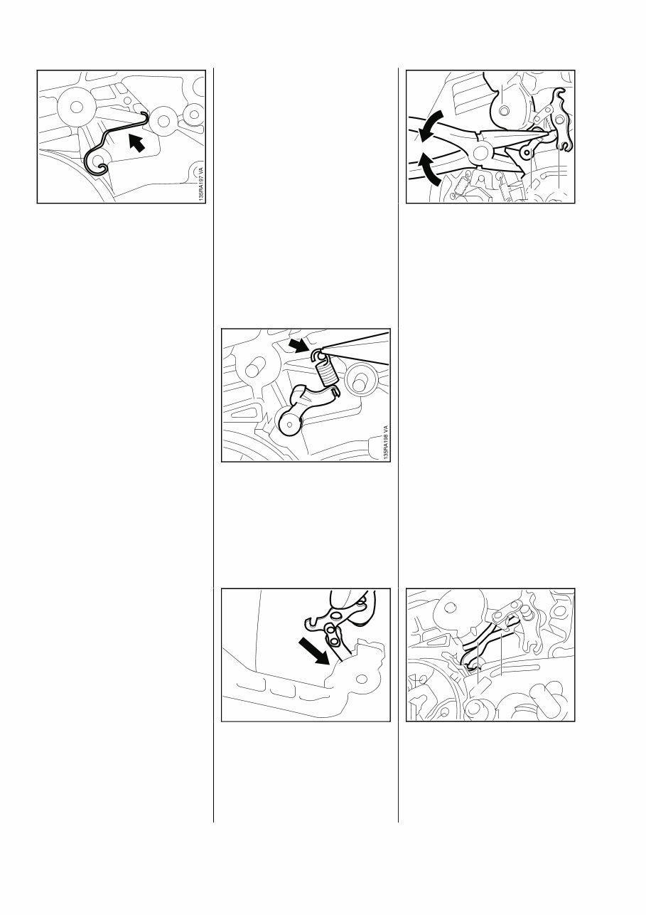
Online version - not for reprint • From serial number X 28 310 255, remove the flat spring. - Inspect parts and replace if damaged. - Clean the entire housing recess for the chain brake. - If the groove of the brake spring anchor pin is worn, replace the housing. - Lubricate sliding and bearing points of chain brake with STIHL multipurpose grease or, preferably, Molykote grease - see 11.2. - From serial number X 28 310 255, install the flat spring. - Up to serial number X 28 310 254, fit the cam lever. • Attach spring to cam lever (open side of spring hook facing outwards) and slip it over the pivot pin • Insert the bell crank in the side of the hand guard so that the short arm of the bell crank points to top of hand guard. • Position the hand guard (1) against the pivot pin and fit the other side of the hand guard over the housing. • Position the bell crank (2) against the pivot pin. • Press the cam lever (3) slightly downward and push the hand guard and bell crank onto their pivot pins. • Check that cam lever or flat spring (1) is properly located on face (2) of hand guard bearing boss. 4.4.3 Assembly VA 135RA034 VA 135RA035 2 1 3 VA 135RA036 1 2 10 021, 023, 025
This OEM Service & Repair Manual is an essential resource for anyone working with Stihl 021, 023, 023 L, and 025 chainsaws and their parts. It features high-quality diagrams and detailed instructions for servicing and repairing your Stihl equipment. Whether you're a professional mechanic or a DIY enthusiast, this manual is a valuable tool that precisely addresses the unique aspects of each model.
The manual covers a range of important topics including:
Introduction
Specifications
Clutch, Chain Drive, Chain Brake, and Chain Tensioner
Engine
Ignition System
Rewind Starter
AV Handle System
Master Control / Handle System
Chain Lubrication
Fuel System
Special Servicing Tools and Aids
This manual is available in PDF format and is compatible with all versions of Windows and Mac. It is an indispensable resource that can help you save time and reduce repair costs by providing accurate, step-by-step directions tailored specifically for Stihl 021, 023, 023 L, and 025 chainsaws. Get your hands on this comprehensive manual and take control of the maintenance and performance of your Stihl equipment today!
Recently Viewed
5,521,897Happy Clients
2,594,462eManuals
1,120,453Trusted Sellers
15Years in Business
Price:
Actual Price:
Stihl 021/023/023 L/025 Chainsaws OEM Service & Repair Manual