2 MS 201, MS 201 C, MS 201 T, MS 201 TC Contents 12. Repair fuel system 93 12.1 Air Filter 93 12.2 Baffle 93 12.3 Filter Base (MS 201) 93 12.3.1 Filter Base (MS 201 T) 94 12.4 Carburetor (MS 201) 94 12.5 Carburetor (MS 201 T) 96 12.5.1 Leakage test 98 12.6 Servicing the Carburetor 99 12.6.1 Metering Diaphragm 99 12.6.2 Inlet Needle 100 12.6.3 Pump Diaphragm 101 12.6.4 Lever on Throttle Shaft 102 12.6.5 Levers on Choke Shaft 102 12.6.6 Adjusting Screws 103 12.7 Adjusting the Carburetor 105 12.7.1 Basic Setting 105 12.7.2 Standard Setting 107 12.8 Intake Manifold 108 12.8.1 Impulse Hose 109 12.9 Tank Vent 110 12.9.1 Testing 110 12.9.2 Tank Vent (MS 201) 111 12.9.3 Tank Vent (MS 201 T) 112 12.10 Fuel Intake 112 12.10.1 Pickup Body 112 12.10.2 Fuel Suction Hose 112 12.10.3 Tank Vent Hose 114 12.10.4 Manual Fuel Pump with Fuel Hoses 116 12.11 Tank Housing Removing and Installing 118 13. Special Servicing Tools 120 14. Servicing Aids 122
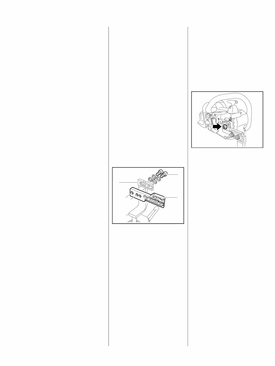
3 MS 201, MS 201 C, MS 201 T, MS 201 TC 1. Introduction and Safety Precautions 1.1 Introduction This service manual contains detailed descriptions of all the repair and servicing procedures specific to this power tool. You should make use of the illustrated parts lists while carrying out repair work. They show the installed positions of the individual components and assemblies. Refer to the latest edition of the relevant parts list to check the part numbers of any replacement parts. A fault on the machine may have several causes. To help locate the fault, consult the chapter on "Troubleshooting" and the "STIHL Service Training System" for all assemblies. Refer to the “Technical Information” bulletins for engineering changes which have been introduced since publication of this service manual. Technical information bulletins also supplement the parts list until a revised edition is issued. The special tools mentioned in the descriptions are listed in the chapter on "Special Servicing Tools" in this manual. Use the part numbers to identify the tools in the "STIHL Special Tools" manual. The manual lists all special servicing tools currently available from STIHL. Symbols are included in the text and pictures for greater clarity. The meanings are as follows: In the descriptions: : Action to be taken as shown in the illustration above the text – Action to be taken that is not shown in the illustration above the text In the illustrations: A Pointer a Direction of movement @ 4.2 =Reference to another chapter, i.e. chapter 4.2 in this example. Service manuals and all technical information bulletins are intended exclusively for the use of properly equipped repair shops. They must not be passed to third parties. Servicing and repairs are made considerably easier if the machine is mounted to assembly stand (3) 5910 890 3101. To do this, secure the mounting plate (2) 5910 850 1650 to the assembly stand with two screws (1) and washers. The screws must not project since they, depending on the machine, may damage housings when the machine is clamped in position. 2710RA320 TG 2 3 1 Preparations for servicing Remove the chain sprocket cover, saw chain, guide bar and clutch drum before carrying out repairs – the chain brake must be disengaged. Mount the machine to the assembly stand for servicing and repair work. Engage the bar mounting stud in the outer bore in the mounting plate and secure the machine in position with the M 8 nut (arrow). The machine is held in position on the mounting plate by the screw head on the crankcase. Always use original STIHL replacement parts. They can be identified by the STIHL part number, the { logo and the STIHL parts symbol K. This symbol may appear alone on small parts. Storing and disposing of oils and fuels Collect fuel or lubricating oil in a clean container and dispose of it properly in accordance with local environmental regulations. 7013RA000 TG
4 MS 201, MS 201 C, MS 201 T, MS 201 TC 1.2 Safety Precautions If the machine is started up in the course of repairs or maintenance work, observe all local and country- specific safety regulations as well as the safety precautions and warnings in the instruction manual. Fuel is extremely flammable and can be explosive in certain conditions. Do not smoke or bring any fire, flame or other source of heat near the fuel. All work with fuel must be performed outdoors only. Spilled fuel must be wiped away immediately. Always perform leakage test after working on the fuel system and the engine. Exercise extreme caution while carrying out maintenance and repair work on the ignition system. The high voltages which occur can cause serious or fatal accidents. Always wear suitable protective gloves for operations in which components are heated for assembly or disassembly. Improper handling may result in burns or other serious injuries. Always replace damaged parts. Check disassembled parts for wear or damage before re-installing – replace as necessary. Run the machine only with the fan housing mounted in position – there is otherwise a risk of injury from the flywheel and a risk of engine damage due to overheating. The chapter on tightening torques lists all machine components that have to be tightened to a specific torque or coated with threadlocking adhesive. The specifications must be maintained when tightening down screws, nuts and other fasteners in all the procedures described in this service manual. Fuel system – hose barb connectors Pull off or push on fuel hoses in line with the connector, preferably by hand, to ensure the tightness of the fuel system. Avoid damaging the hose barb – do not use sharp-edged pliers, screwdrivers, etc. Do not cut open fuel hoses with a knife or similar tool. Do not re-use fuel hoses after removal. Always install new hoses – fuel hoses can be overstretched during removal. Install new fuel hoses either dry or with the aid of STIHL press fluid – coat the ends of hoses and the connectors, b 14. Other press fluids are not approved and may result in damage to the fuel hoses.
5 MS 201, MS 201 C, MS 201 T, MS 201 TC 2. Specifications 2.1 Engine MS 201 MS 201 T Displacement: 35.2 cm 3 35.2 cm 3 Bore: 40.0 mm 40.0 mm Stroke: 28.0 mm 28.0 mm Engine power to ISO 7293: 1.8 kW (2.4 bhp) at 9,500 rpm 1.8 kW (2.4 bhp) at 9,500 rpm Cut-off speed with bar and chain: 14000 rpm 14000 rpm Idle speed: 3,000 rpm 3,000 rpm Clutch: Centrifugal clutch without linings Centrifugal clutch without linings Clutch engages at: 3,700 rpm 3,700 rpm Crankcase leakage test at gauge pressure: 0.5 bar under vacuum: 0.5 bar 2.2 Fuel System Carburetor leakage test at gauge pressure: 0.8 bar 0.8 bar Operation of tank vent at gauge pressure: 0.5 bar 0.5 bar Fuel: as specified in instruction manual as specified in instruction manual 2.3 Ignition System Air gap between the ignition module and flywheel: 0.30 (+ 0.05/- 0.10) mm 0.30 (+ 0.05/- 0.10) mm Spark plug (resistor type): NGK CMR 6 H NGK CMR 6 H Electrode gap: 0.5 mm 0.5 mm 2.4 Chain Lubrication Speed-controlled oil pump with reciprocating piston and manual flow control or Ematic Settings for oil delivery rate: min.: max.: Ematic: 3.5 (+/1.0) cm 3 /min at 7,000 rpm 9.5 (+/2.0) cm 3 /min at 10,000 rpm 6.5 (+/1.5) cm 3 /min at 10,000 rpm 3.5 (+/1.0) cm 3 /min at 7,000 rpm 9.5 (+/2.0) cm 3 /min at 10,000 rpm 6.5 (+/1.5) cm 3 /min at 10,000 rpm
6 MS 201, MS 201 C, MS 201 T, MS 201 TC 2.5 Tightening Torques DG and P (Plastoform) screws are used in polymer and light metal components. These screws form a permanent thread when they are installed for the first time. They can be removed and installed as often as necessary without impairing the strength of the screwed assembly, providing the specified tightening torque is observed. For this reason it is essential to use a torque wrench. Fastener Thread size For component Torque Nm Remarks Screw M 4x12 Chain tensioner cover / crankcase 1.8 2) 4) Screw M 4x16 Antivibration element on oil tank / crankcase 4.0 3) Collar stud M 8 Collar stud for bar 22.0 1) Screw P 4x14 Cover / chain sprocket cover 1.5 Screw M 4x12 Cover, oil pump / crankcase 2.0 2) 4) Screw M 4x9.6 Spark arresting screen / muffler 2.0 Screw P 6x19 Handle housing / front handle (MS 201) 6.0 Screw P 6x19 Handle housing / front handle (MS 201 T) 3.5 Screw M 4x16 Handlebar / crankcase 4.0 3) Screw P 4x14 Handle molding / handle housing 1.5 Screw P 6x19 Retainer, ring / tank housing 6.0 Screw P 4x10 Clamp, wiring harness / handle housing (MS 201) 1.8 Screw P 4x10 Clamp, ignition lead 1.8 Screw M 5x16 Chain catcher / spiked bumper / crankcase 10.0 2) 4) Screw M 5x16 Spiked bumper / crankcase 10.0 2) 4) Screw M 4x12 Manifold / cylinder 3.0 2) 4) Screw M 4x16 Crankcase, sprocket side/fan side 4.5 2) 4) Screw P 5x16 Bearing plug / handle housing 3.0 Screw M 4x16 Fan housing / crankcase 4.0 2) 4) Screw P 5x16 Fan housing / tank housing 4.0 Carrier M 8x1 L Carrier / crankshaft 25.0 Screw M 4x12 Oil pump / crankcase 3.5 2) Screw P 5x29.5 Annular buffer / handle housing 3.0 Screw P 4x14 Annular buffer / tank housing 1.5 Screw P 4x10 Rewind spring retainer 1.5 Screw M 5x16 Muffler / cylinder, stage 1 (tightening first screw) 2.5 2) 3) Screw M 5x16 Muffler / cylinder, stage 2 (tightening second screw) 10.0 2) 3) Screw M 5x16 Muffler / cylinder, stage 3 (tightening first screw) 10.0 2) 3) Collar stud M 5x18 Bar mounting / crankcase 7.0 2) 3) Nut M 8x1 Flywheel / crankshaft 23.0 6) Screw P 4x10 Insulating plate (MS 201) 1.5
7 MS 201, MS 201 C, MS 201 T, MS 201 TC Fastener Thread size For component Torque Nm Remarks Screw M 4x16 Tank housing / crankcase 4.5 2) 4) Screw M 5x43 Carburetor / handle housing, stage 1 0.8 5) Screw M 5x43 Carburetor / handle housing, stage 2 3.0 5) M 10x1 Spark plug / cylinder 12.0 Screw M 4x20 Ignition module / crankcase 4.0 3) Screw M 5x20 Cylinder / crankcase 10.0 2) 4) Remarks: 1) Loctite 272, high strength up to 250 °C (482 °F) 2) Screws with binding head 3) Micro-encapsulated screws 4) Waxed screws 5) Bright and waxed screws 6) Degrease crankshaft/flywheel and mount oil-free Use the following procedure when refitting a DG or P screw in an existing thread: Place the screw in the hole and rotate it counterclockwise until it drops down slightly. Tighten the screw clockwise to the specified torque. This procedure ensures that the screw engages properly in the existing thread and does not form a new thread and weaken the assembly. Before reinstalling a micro-encapsulated screw, clean both threads (screw tap into female thread by hand and then blow out with compressed air, clean male thread with brush), coat clean screw with medium strength Loctite 242 or 243. Power screwdriver setting for polymer: DG and P screws max. 500 rpm Do not use an impact wrench for releasing or tightening screws. Do not mix up screws with and without binding heads.
8 MS 201, MS 201 C, MS 201 T, MS 201 TC 3. Troubleshooting 3.1 Clutch Condition Cause Remedy Saw chain stops under full load Clutch shoes badly worn Install new clutch Clutch drum badly worn Install new clutch drum Saw chain rotates at idle speed Engine idle speed too high Readjust idle speed screw LA Clutch springs stretched Replace the clutch springs or install new clutch Clutch springs broken Replace the clutch springs Loud noises Clutch springs stretched Replace all clutch springs Clutch shoe retainer broken Install new retainer or clutch Clutch shoes and carrier worn Install new clutch Needle cage damaged Fit new needle cage
9 MS 201, MS 201 C, MS 201 T, MS 201 TC 3.2 Chain Drive, Chain Brake, Chain Tensioner Condition Cause Remedy Chain sprocket wears rapidly Chain not properly tensioned Tension chain as specified Wrong chain pitch Fit chain of correct pitch Insufficient chain lubrication Check chain lubrication Saw chain stops under full load Clutch shoes badly worn Install new clutch Clutch drum badly worn Install new clutch drum Brake band blocked Check freedom of movement and operation of brake band Saw chain rotates at idle speed Engine idle speed too high Readjust idle speed screw LA Clutch springs stretched Replace the clutch springs or install new clutch Clutch springs broken Replace the clutch springs Saw chain does not stop immediately when brake is activated Brake spring stretched or broken Fit new brake spring Brake band stretched or worn Fit new brake band Clutch drum worn Install new clutch drum
Discover the Stihl MS201 and MS201T Chainsaw Full Service & Repair Manual, a comprehensive resource for all your chainsaw maintenance needs. This complete factory workshop manual is designed to provide professional mechanics, technicians, and DIY enthusiasts with step-by-step instructions, detailed exploded diagrams, and pictures.
This professional manual covers a wide range of repairs, servicing, and troubleshooting procedures without any extra fees or expiry dates. Its extensive content, consisting of hundreds of pages filled with detailed photos and diagrams, ensures that you have all the information you need to successfully complete any job correctly.
One of the great features of this manual is its versatility. Whether you prefer to access it on your computer, tablet, or smartphone, it is available for instant download. You can even print out a single page or the entire manual, giving you the flexibility to work in the way that suits you best.
Worried about compatibility? Rest assured, this manual works seamlessly on both Windows and MAC computers, making it accessible to a wide range of users. Plus, there are no limitations or trial periods – this is the full manual that you can use for life without the need for any renewals or additional payments.
If you're in need of a reliable and comprehensive chainsaw service and repair manual, look no further than the Stihl MS201 and MS201T Chainsaw Full Service & Repair Manual.
Recently Viewed
5,521,897Happy Clients
2,594,462eManuals
1,120,453Trusted Sellers
15Years in Business
Price:
Actual Price:
Stihl MS201, MS201T Chainsaw Full Service & Repair Manual