

McCulloch Chainsaws Service & Repair Manual
What's Included?
Fast Download Speeds
Offline Viewing
Access Contents & Bookmarks
Full Search Facility
Print one or all pages of your manual

Two-Stroke
Engine Repair
& Maintenance

This page intentionally left blank

1
Fundamentals
There comes a time when work stops and the mechanic becomes abstracted, dis-
tant from the task at hand. Something about the machine does not conform to the
picture in the mechanic’s mind. Images flash by until he or she finds one that most
closely conforms to actual conditions. Once that is done, repairs can begin.
Constructing visual images is what mechanics do; the other stuff is mere
wrench-twisting.
This chapter provides grist for these mental images. Because the material
must be conveyed in words, it tends to be abstract. But once you can picture
how these engines work, you will have made the first step in the journey to
becoming a real mechanic.
Spark-ignition engines operate in a cycle consisting of four events: intake,
compression, expansion (or power), and exhaust. A fresh charge of air and
fuel is inducted into the cylinder, which then is compressed by the piston
and ignited by the spark plug. The pressure created by combustion reacts
against the piston to generate torque on the crankshaft. The spent gases
then exhaust into the atmosphere.
Four-stroke-cycle engines require four up and down strokes of the piston, or two
full crankshaft revolutions, to complete the cycle. Two-stroke-cycle engines tele-
scope events into two strokes or one crankshaft revolution. For convenience we
abbreviate the terms to four-cycle or four-stroke, and two-cycle or two-stroke.
Two-cycle operation
Focus on the piston. The double-acting piston works in both directions to
compress the air-fuel mixture in the cylinder above it and in the crankcase
below it. The piston and connecting rod convert a portion of the heat and
1

energy released by combustion into mechanical motion that turns the crank-
shaft. Were that not enough, the piston also acts as a slide valve to open and
close exhaust, transfer and (in some applications) intake ports. Because it
works so hard, the piston is the first mechanical part to fail on two-cycle
engines.
Third-port engines
Third- or piston-ported engines have three ports cast or milled into their
cylinder liners. The inlet port admits fuel to the crankcase, the transfer port
conveys fuel from the crankcase into the combustion chamber, and the
exhaust port opens to the atmosphere.
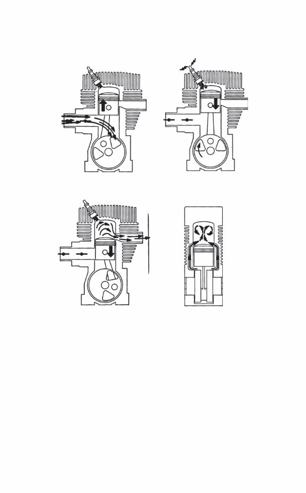
First, let’s look at events above the piston during a full turn of the crank-
shaft. In Fig. 1-1A the piston approaches the upper limit of travel, or top
dead center (TDC), and has compressed the air-fuel mixture above it. The
piston has also uncovered the inlet port to admit fuel and air from the car-
buretor to the crankcase. Figure 1-1B illustrates the beginning of the power
stroke under the impetus of expanding combustion gases. As the piston
falls, it first uncovers the exhaust port (Fig. 1-1C) and, a few degrees of
crankshaft rotation later, the transfer port (Fig.1-1D). Fuel and air pass
through the transfer port and into the cylinder bore.
Meanwhile, much is happening in the crankcase. As the piston falls on
the power stroke, it partially fills the crankcase, reducing its volume, as
shown in Fig. 1-1C. Since the piston now covers the inlet port, the pressure
of the air-fuel mixture trapped in the case rises.
Near bottom dead center (BDC) the piston uncovers the transfer port and
the pressurized fuel mixture passes through this port to the upper cylinder
(Fig. 1-1D). The piston then rounds BDC and begins to climb, an action that
simultaneously compresses the mixture above the piston and creates a par-
tial vacuum under it. Once the inlet port opens, atmospheric pressure forces
fuel and air from the carburetor into the crankcase.
A problem with third-port engines is fuel reversion. At low speeds the
crankcase fills to overflowing. When the piston reverses at the top of the
stroke, some of the charge can flow back through the inlet port to the car-
buretor. A fog of oily fuel hovers around the air cleaner, dirtying the engine
and playing havoc with carburetor metering.
Reed-valve engines
Although third-port engines are still encountered, many manufacturers prefer to
control crankcase filling with a reed valve installed between the carburetor and
crankcase. The valve, similar to the reed on musical instruments, opens and
closes in response to crankcase pressure (Fig. 1-2). Utility engines make do with
a single reed, or pedal, athwart the intake port (Fig. 1-3). High-performance
2 Fundamentals
Two-cycle operation 3
Transfer
D
Intake
A
Power stroke
B
C
Exhaust
FIG. 1-1. Operating sequence of a third-port, loop-scavenged engine. Walbro
engines employ a tent-like valve block with multiple reeds. This arrangement
provides a large valve area for better crankcase filling (Fig. 1-4).
For mini-two-strokes, the position of the carburetor indicates the type of
inlet valve: when a reed is present, the carburetor mounts on the crankcase
(Fig. 1-5). Third-port engines mount their carburetors on the cylinder barrel
in line with the inlet port, as shown in Fig. 1-6. Being able to recognize the
presence of a reed valve without disassembling the engine is useful, since the
reed can malfunction. Should the pedal split or fail to seal, the engine will
not start.
But the rule about the carburetor location does not necessarily apply to
larger engines. Some European motorcycles had crankcase-mounted carbu-
retors that fed through a rotary valve in the form of a partially cutaway disk,
keyed to crankshaft. Model airplane engines and a few vintage outboards
use a slotted crankshaft to the same effect.
Motorcycle engines often combine a third port with an integral reed valve.
The port controls timing and the reed prevents backflow through the carbu-
retor. Although the reeds impose a pressure drop, midrange torque benefits.
4 Fundamentals
A
C D
B
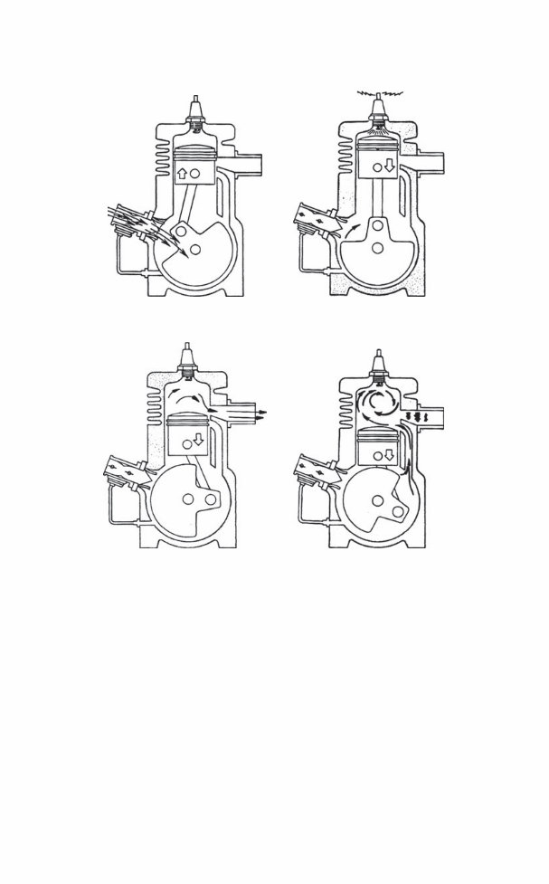
FIG. 1-2. Operating sequence of a reed-valve engine that in the example shown
employs loop scavenging. The small tube on the lower left of the drawing transfers
crankcase pressure pulses to the fuel pump. Deere and Company
5
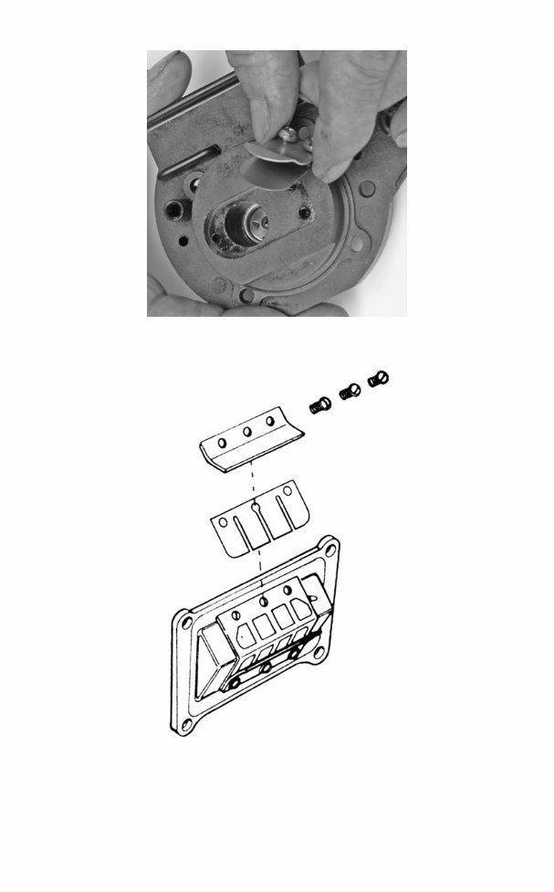
FIG. 1-3. Reed valves for handheld engines generally have a single pedal backed by
a guard plate to limit deflection. Robert Shelby
FIG. 1-4. Multiple pedals are standard on high-performance engines. While there
has been considerable experimentation with fiberglass, carbon fiber, and other
high-tech materials, spring-steel pedals appear to work as well as any. Tecumseh
Products Co.
6 Fundamentals
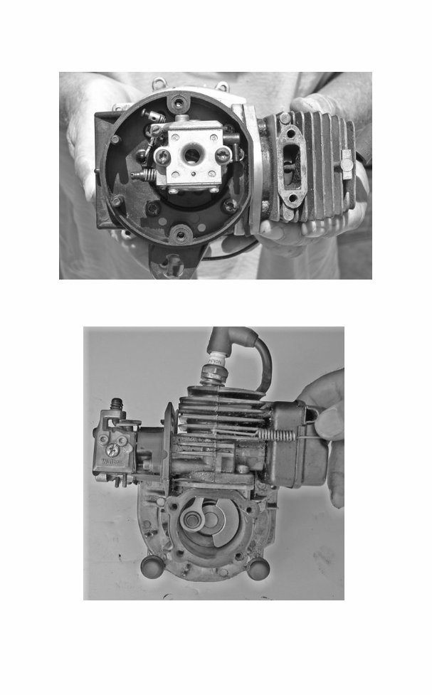
FIG. 1-5. Reed-valve engines mount their carburetors low on the crankcase. Robert
Shelby
FIG. 1-6. Carburetors for third-port engines attach to the cylinder. Some of these
engines incorporate a reed valve in the third port. Robert Shelby

Scavenging
Scavenging is the term for purging the cylinder of exhaust gases. Unlike a four-
cycle engine, which devotes a full stroke of the piston to clear the cylinder, a
two-stroke must scavenge during the 100° or so of crankshaft rotation that the
exhaust port remains open.
Blowdown As the piston falls, it first uncovers the exhaust port and then,
5° or 10° of crankshaft rotation later, the transfer port. Blowdown occurs dur-
ing this brief period that, at wide-open throttle, occupies no more than one
or two thousandths of a second. In spite of its brevity, the blowdown phase
is the primary mechanism for evacuating the cylinder.
The rapid opening of a port releases a high-pressure slug of exhaust gas that
trails a low-pressure zone or wave in its wake. Cylinder pressure momentarily
drops below atmospheric pressure. Responding to the pressure differential, the
fresh charge moves through the transfer port to fill the cylinder. At part throttle,
crankcase pressure is less than cylinder pressure. Were it not for the drop in cylin-
der pressure that accompanies blowdown, two-cycle engines would not run.
The need to accelerate exhaust gases quickly explains why exhaust ports for
high-performance engines are rectangular rather than round. It also explains
why we must keep these ports and mufflers free of carbon accumulations.
Exhaust tuning When a high-pressure wave encounters a solid obstacle
or an abrupt change in direction in the exhaust plumbing, it rebounds back
to the exhaust port. These waves oscillate at the speed of sound and at a
frequency determined by engine rpm. Where space permits, the length of
the exhaust system can be tuned to reflect a high-pressure wave back to the
exhaust port just as the cylinder fills to overflowing. The wave rams any fuel
that spills out of the port back into the cylinder where it belongs. Of course,
this works only over a narrow rpm range; at other speeds the wave can
arrive early to the detriment of cylinder filling. In a similar manner, the
intake tract can be tuned to maximize crankcase filling.
Spatial constraints make tuned exhaust and intake systems impractical for
handheld equipment. About all that can be done is to arrange for a small boost
from third- or fourth-order wave harmonics.
Charge scavenging What exhaust gas remains in the cylinder after blow-
down must be scavenged by the fuel charge, which enters the cylinder at
velocities as high as 65 m/s. Charge scavenging takes two forms, neither of
which can entirely eliminate short-circuiting.
Short-circuiting Short-circuiting is the term for the way incoming fuel
escapes out the exhaust, as if one were trying to fill a leaky bucket. Most of
the leak can be laid to symmetrical timing.
Because piston motion controls port timing, the timing is symmetrical
around BDC. For example, an exhaust port that opens 60 crankshaft degrees
Two-cycle operation 7

before bottom dead center must remain open for 60° after BDC. The exhaust
port opens a few degrees before the transfer port. Otherwise, the cylinder
would not blow down and very little fuel would be delivered. But opening the
exhaust port early means that it stays open throughout the entire fuel transfer
process.
The open exhaust port acts as an escape hatch for incoming fuel. How
much fuel escapes combustion varies with port geometry, rpm, and throttle
position. An idling motorcycle short-circuits as much as 70% of its fuel out
the exhaust. On average, two-stroke engines waste between 25% and 35%
of their fuel in this manner.
Cross scavenging Readers with long memories may recall the deflec-
tor pistons that were once standard ware on these engines (Fig. 1-7).
8 Fundamentals
Intake port
Exhaust port
Deflector
FIG. 1-7. Cross-scavenged engines have the intake port 180° opposite the exhaust
port. Incoming gases rebound upward off the deflector on the piston crown to give
some protection against short-circuiting.
You're Reading a Preview
What's Included?
Fast Download Speeds
Offline Viewing
Access Contents & Bookmarks
Full Search Facility
Print one or all pages of your manual
$30.99
Viewed 17 Times Today


Secure transaction
What's Included?
Fast Download Speeds
Offline Viewing
Access Contents & Bookmarks
Full Search Facility
Print one or all pages of your manual
$30.99
These manuals cover a wide range of models including:
- 10-10 Auto
- 7-10 Auto
- Double Eagle 50
- Double Eagle 80
- Eager Beaver
- Eager Beaver 2.1
- Eager Beaver 2.3
- Eager Beaver 3.7
- Eager Beaver 2010
- Eager Beaver 2014
- Eager Beaver 2016
- Eager Beaver 2116
- Eager Beaver 2316
- Eager Beaver 2318 Super
- Mac 110
- Mac 120
- Mac 130
- Mac 140
- Mac 3210
- Mac 3214
- Mac 3216
- Mac 3516
- Mac 3818
- Mac 4600
- Mac 4900
- MacCat
- MacCat Super 16
- MacCat Super 18
- Mini-Mac 25
- Mini-Mac 30
- Mini-Mac 35
- PM10-10S
- PM55
- PM60
- PM155
- PM165
- PM310
- PM320
- PM330
- PM340
- PM355
- PM365
- PM375
- PM380, PM380AS
- PM510
- PM515
- PM555
- PM605
- PM610 & SUPER 610
- PM650
- PM655
- PM700
- PM800
- PM805
- PM850
- PM1000
- Power Mac 6
- Pro Mac 3205
- Pro Mac 3505
- Pro Mac 3805
- Pro Mac 4700
- Pro Mac 5000
- Silver Eagle 2012
- Silver Eagle 2014
- Silver Eagle 2016
- Silver Eagle 2116
- Silver Eagle 2318
- Silver Eagle 2818
- Silver Eagle 3020
- SP60
- SP80
- SP81
- SP40
- TimberBear
- Titan 35
- Titan 40
- Titan 50
- Titan 57
- Wildcat


