

JONSERED CHAINSAW FACTORY Repair Manual
What's Included?
Fast Download Speeds
Online & Offline Access
Access PDF Contents & Bookmarks
Full Search Facility
Print one or all pages of your manual

1
Workshop Manual
Chain Saws
Contents
This manual covers models:
2036/2040
2041/2045/2050
2054/2055
625/630/670
2077/2083
2095
General recommendations 2
1. Safety equipment 3
2. Starter unit 17
3. Electrical system 23
4. Fuel system 35
5. Centrifugal clutch 55
6. Lubrication system 65
7. Cylinder and piston 77
8. Crankshaft and crankcase 93
9. Tools 115
10. Technical data 127
Downloaded from www.Manualslib.com manuals search engine
2
502 51 02-01
General recommendations
Keep this in mind:
– Do not start the engine without the clutch and clutch drum fitted.
– Do not touch hot parts such as the silencer and clutch before
they have cooled sufficiently to avoid burn injuries.
– Avoid getting petrol on bare skin or in the mouth.
– Wipe up spilled oil immediately from the floor to avoid slipping
and subsequent injury.
– Do not use tools which are worn or fit badly, e.g. nuts and
screws.
– Never start the engine indoors. Exhaust fumes are toxic!
+ Always work on a tidy work bench.
+ Always work methodically to be sure that all parts are correctly
assembled and that screws and nuts are tightened.
+ Use protective cream on your hands. It reduces the risk of
infection and enables dirt to be more easily washed off.
Prolonged contact with motor oil can be hazardous to health.
+ Use special tools when so recommended in order to work
correctly.
Fire hazard
Handle petrol with respect since it is highly inflammable.
Do not smoke and make sure that there are no naked flames or
sparks in the vicinity.
Make sure that there is a functioning fire extinguisher in the vicinity.
Do not attempt to extinguish a petrol fire with water.
Toxic fumes
Read the instructions carefully when using cleaning liquids.
Make sure that there is adequate ventilation when handling petrol,
trichloroethylene and other viscous liquids.
The engine exhaust fumes are toxic. Test run the engine only when
there is good ventilation, preferably outdoors.
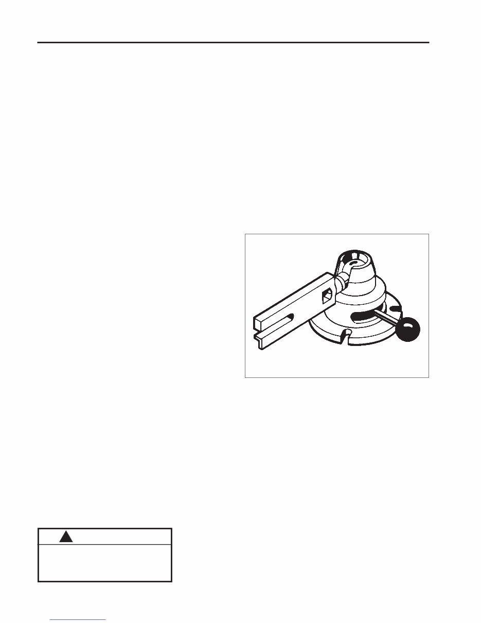
Special tools
Some work operations in this workshop manual require the use
of special tools. In each section where this is appropriate the tool
and order number are illustrated.
We recommend the use of special tools partly to avoid personal
injury and partly to eliminate expensive damage to the
components in question.
Sealing surfaces and gaskets
Make sure that all sealing surfaces are clean and free from the
residue of old gaskets. Use a tool which will not damage the
sealing surface when cleaning it. Scratches and irregularities
are removed with a fine, float cut file.
Sealing rings
Always replace a sealing ring which has been dismantled. The
sensitive sealing lip can easily be damaged and result in poor
sealing capacity. The surface which the seal seals must also be
completely undamaged. Lubricate the sealing lip with grease
before it is fitted and make sure that it is not damaged, e.g. by
shoulder and splines on a shaft. Use tape or conical sleeve as
protection. It is important that the sealing ring is correctly turned
for it to function as intended.
The engine exhaust from this product
contains chemicals known to the State
of California to cause cancer, birth
defects or other reproductive harm.
WARNING !
Downloaded from www.Manualslib.com manuals search engine
3
Safety equipment
1
1.
Contents
Dismantling 4
Disassembly 4
Fitting 6
Dismantling, mod. 2054/2055 7
Fitting, mod. 2054/2055 9
Dismantling, mod. 2077/2083 10
Fitting, mod. 2077/2083 11
Checking of automatic function 12
Checking of brake action 13
Chain catcher 13
Throttle lock 13
Downloaded from www.Manualslib.com manuals search engine

4
Safety equipment 1
!
505 38 17-05
!
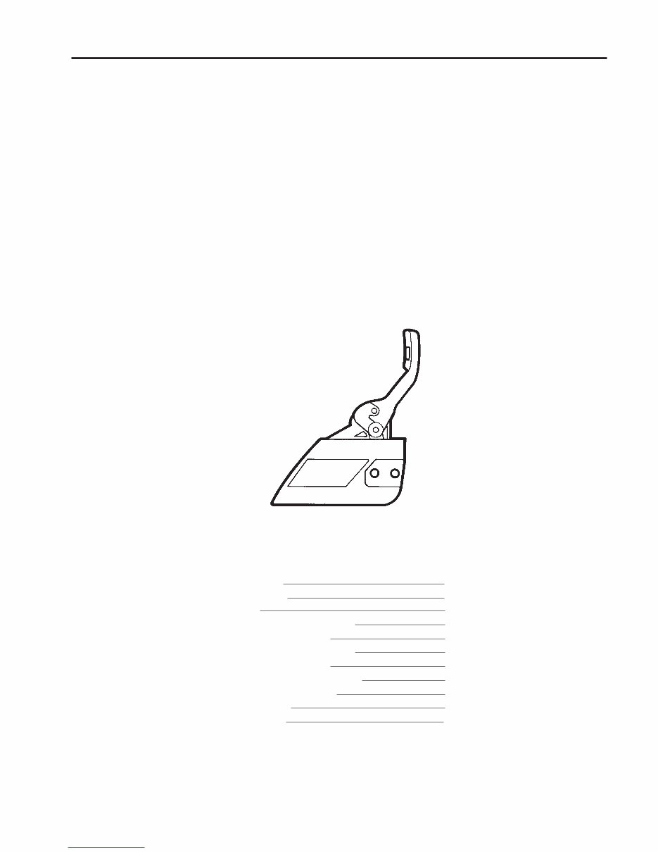
In addition to the chain brake the chain catcher and
right-hand guard on the rear handle are also con-
sidered part of the chain saw’s safety equipment.
It is obviously important that the chain brake
functions as intended, but it is also important that
the chain catcher is undamaged and in position. In
the event of a chain break this will catch up the
chain so that the hand will not be injured.
WARNING!
Protective goggles must be
worn during all work on the
chain brake to prevent perso-
nal injury if for some reason the
brake spring should fly off.
Dismantling
Dismantle the chain brake from the chain
saw.
Disassembly
Release the chain brake.
Press out the one half of the hand guard’s
bearing.
Press out the other half of the hand guard’s
bearing.
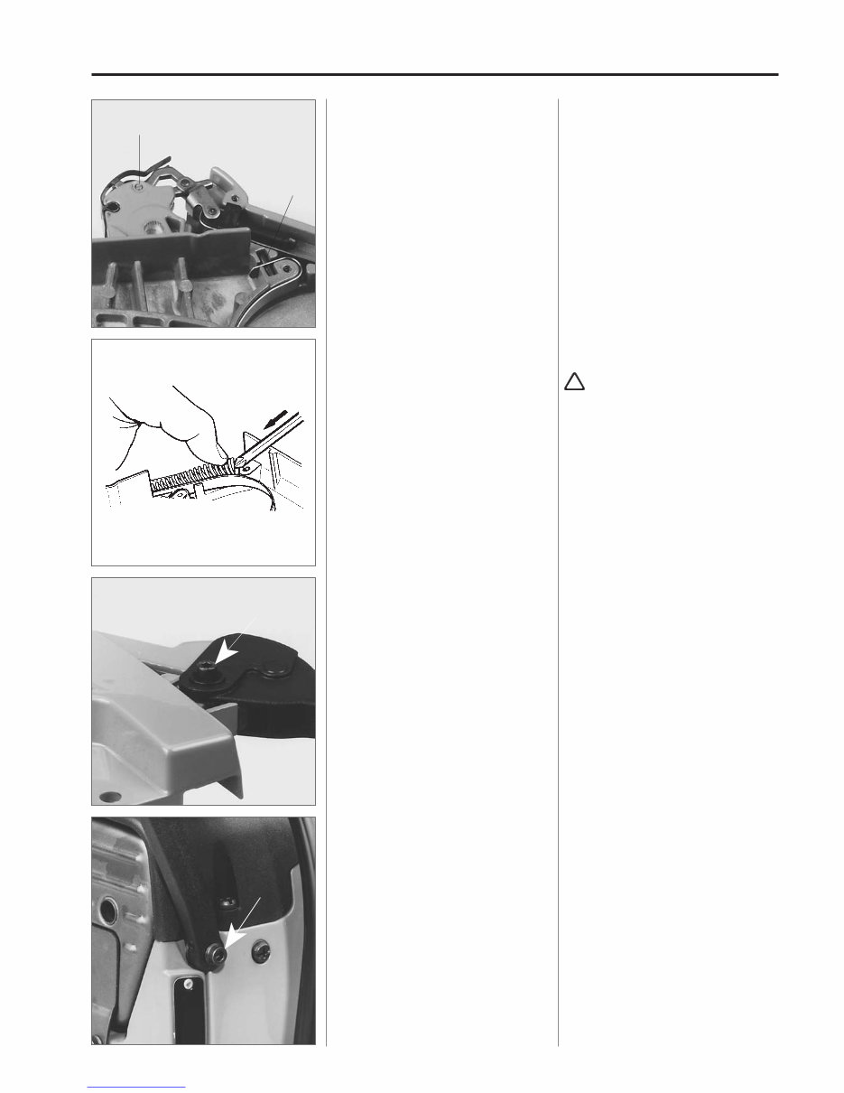
Dismantling
Remove the guide bar's attachment nuts
and lift off the clutch cover with the chain
brake.
Clean from sawdust and dirt.
WARNING!
The brake spring is tensioned with a
very large force and can cause per-
sonal injury if the brake is not
released prior to further work.
Disassembly
Release the chain brake.
Unscrew the screw to the hand guard’s
bearing completely, and then screw in
approx. 2 turns.
Drive out the bearing by tapping the screw
with a hammer.
Press out the other half of the bearing by
means of suitable mandrel, e.g.
505 38 17-05.
Lift off the hand guard.
Downloaded from www.Manualslib.com manuals search engine

5
Safety equipment 1
!
Remove the screws and the cover over
the brake spring.
Bend up the brake spring.
Press out the toggle-joint’s bearing pin
and lift off the complete brake mechanism.
Press out the plate spring with a suitable
mandrel.
Remove the screws and lift off the cover
over the brake spring.
WARNING!
The brake spring is tensioned and
can slip out of its position.
Use a screwdriver and carefully bend up
the spring.
Press out the toggle-joint’s bearing pin by
means of a suitable mandrel.
Lift off the complete brake mechanism.
Press out the plate spring with a suitable
mandrel, and replace if necessary.
Clench the spring eye with a pair of pliers
so that it is easier to fit the new spring.
Downloaded from www.Manualslib.com manuals search engine

6
Safety equipment 1
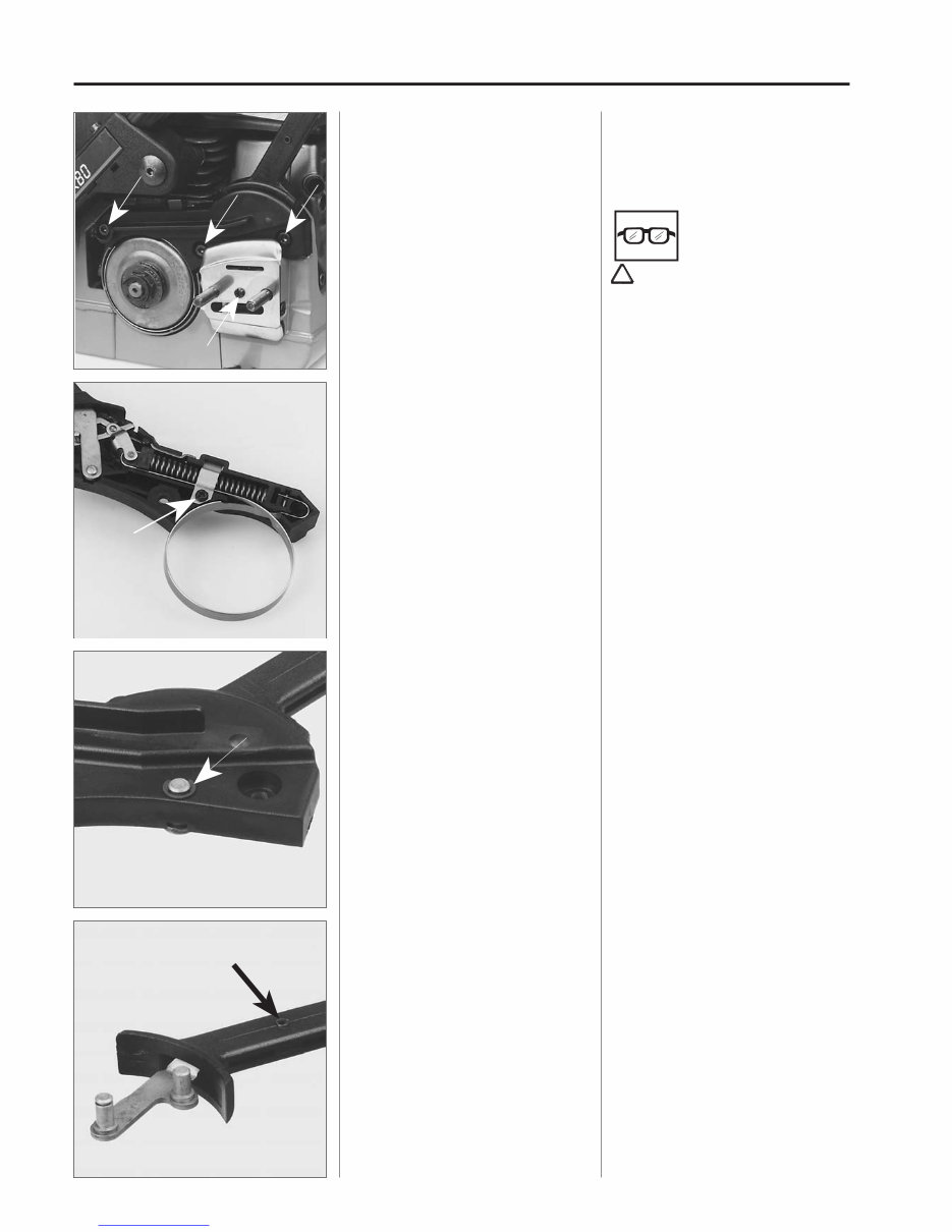
0,8 mm
The brake band must have a minimum
thickness of 0.8 mm at the most worn
point.
Remove the screw and replace the brake
band.
Dismantle the lock-ring and the pin in
order to replace the spring inside the
hand guard.
Assembly
Grease the spring and fit it in the hand
guard.
Check the wear on the brake band.
At the most worn point the band must
have a thickness of at least 0.8 mm.
Otherwise it should be replaced with a
new band.
Remove the screw and fit a new brake
band.
Check after fitting that the brake band
does not touch the toggle-joint and ob-
struct its movement.
Inside the hand guard there is a spring
which is accessible for replacement after
the lock-ring and pin are dismantled.
Use a small screwdriver to remove the
lock-ring.
Assembly
Grease the spring and push it in the hand
guard as far as it goes.
Fit the pin and lock-washer.
NOTE!
The pin should not go through the eye on
the spring.
Check that the spring is turned correctly.
Downloaded from www.Manualslib.com manuals search engine
7
Safety equipment 1
!
A
B
Fit the brake mechanism in the clutch
cover.
Lubricate the bearing points with thin oil.
Press down the brake spring by means of
a Phillips screwdriver.
Fit the cover.
Grease the bearing surfaces and fit the
hand guard.
Check that the brake functions.
Dismantling
Mod. 2054/2055
Remove the screw, sleeve and washer
for the hand guard’s bearing on the star-
ter unit side, including the clutch cover,
guide bar and chain.
Clean!
Place the brake mechanism in position
on the clutch cover.
Press in the toggle-joint’s bearing pin (A)
and place the tubular pin (B) in position.
Lubricate the bearing points with thin oil.
Press down the brake spring in the clutch
cover by means of a Phillips screwdriver.
WARNING!
Observe care to avoid injury if the
screwdriver slips.
Fit the cover over the spring mechanism.
Grease the bearing points for the hand
guard.
Press down the hand guard over the
bearing and fit both bearing sleeves.
NOTE!
Check that the bearing sleeves are placed
on the correct side.
Tension and release the chain brake a
number of times to check that it functions.
Dismantling
Mod. 2054/2055
On these models the chain brake’s hand
guard has an extra bearing point on the
starter unit side.
Remove the screw, sleeve and washer
for this bearing.
Remove the clutch cover, guide bar and
chain.
Clean from sawdust and dirt.
Downloaded from www.Manualslib.com manuals search engine
8
Safety equipment 1
Dismantle the protective plate over the
guide bar attachment and the chain brake.
Release the chain brake!
Remove the plate clamp over the brake
spring and bend away the spring.
Remove the lock-ring round the hand
guard’s bearing pin and lift off the brake
mechanism.
Replace the plate insert in the hand guard
if the pins are worn by first pressing out
the fitted pin.
Remove the protective plate over the
guide bar attachment.
Remove the screws and lift off the chain
brake.
Release the chain brake!
!
WARNING!
The brake spring is tensioned with a
very large force and can cause per-
sonal injury if the brake is not released
prior to further work.
Remove the screw and plate clamp over
the brake spring.
Carefully bend away the spring by means
of a screwdriver.
NOTE!
The spring has a certain tension even
when the brake is released, and therefore
it should be dismantled carefully.
Remove the lock-ring round the hand
guard’s bearing pin and lift off the brake
mechanism.
If the pins on the plate insert in the hand
guard are worn the complete insert can
easily be replaced.
Press out the fitted pin with a suitable
mandrel and replace the insert.
Downloaded from www.Manualslib.com manuals search engine

9
Safety equipment 1
0,8 mm
Dismantle the brake mechanism and
replace worn or damaged parts.
Fit the brake spring and plate clamp over
the spring.
Fit the chain brake on the crankcase.
Screw tight the cover plate over the guide
bar attachment and fit the brake’s bearing
on the starter unit side.
Dissassemble the brake mechanism and
replace worn or damaged parts.
The brake band should have a minimum
thickness of 0.8 mm at the most worn
place.
Assembly
Mod. 2054/2055
Fit the brake in the reverse order to dis-
mantling.
Begin with by fitting the hand guard.
Lubricate all moving parts with thin oil.
Fit the brake spring by means of a Phillips
screwdriver.
WARNING!
Observe care to avoid injury if the
screwdriver slips.
!
Fit the plate clamp over the spring.
Fit the chain brake on the crankcase.
NOTE!
Make sure that the guide pin on the brake
fits into the hole in the crankcase before
the screws are tightened.
Fit the cover plate on the guide bar attach-
ment.
Screw tight the screw for the brake’s
bearing on the starter unit side.
Do not forget the washer between the
crankcase and brake!
Downloaded from www.Manualslib.com manuals search engine
10
Safety equipment 1
!
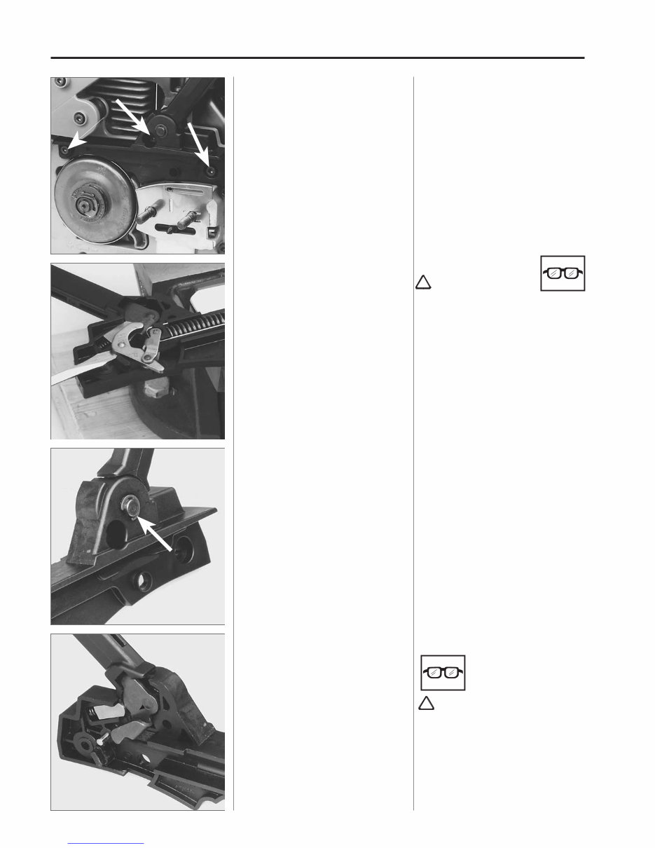
Dismantling
Mod. 2077/2083
Dismantle the chain brake’s bearing on
the starter unit side.
Remove the clutch cover, guide bar and
chain.
Clean!
Remove the screws and lift off the chain
brake.
Release the chain brake!
Lift up the toggle-joint carefully by means
of a screwdriver.
Dismantle the hand guard.
Press the hand guard out of the bearing.
Dismantling
Mod. 2077/2083
Remove the screw, sleeve and washer
for the chain brake’s bearing on the star-
ter unit side.
Remove the clutch cover, guide bar and
chain.
Clean from sawdust and dirt.
Remove the screws and lift off the chain
brake.
Release the chain brake!
!
NOTE!
The other end of the spring is controlled
by a pin which goes into the centre.
For this reason do not try to lift up the
spring there.
Dismantle the hand guard.
Remove the lock-ring by means of a small
screwdriver.
Hold your thumb over so that the ring
does not fly away.
Press out the hand guard from the bearing.
WARNING!
Observe care so that the sprin loaded
catch does not fly away.
WARNING!
The brake spring is tensioned with a
very large force and can cause perso-
nal injury if the brake is not released
prior to further work.
Lift up the toggle-joint carefully by
means of a screwdriver.
Hold your hand over.
Downloaded from www.Manualslib.com manuals search engine
You're Reading a Preview
What's Included?
Fast Download Speeds
Online & Offline Access
Access PDF Contents & Bookmarks
Full Search Facility
Print one or all pages of your manual
$31.99
Viewed 90 Times Today


Secure transaction
What's Included?
Fast Download Speeds
Online & Offline Access
Access PDF Contents & Bookmarks
Full Search Facility
Print one or all pages of your manual
$31.99
JONSERED FACTORY REPAIR MANUAL
- This manual covers models:
- 2036/2040
- 2041/2045/2050
- 2054/2055
- 625/630/670
- 2077/2083
- 2095
Useful for both professional mechanics and DIY enthusiasts, this manual covers all aspects of your chainsaw, including:
- Engine repair
- Carburetor repair
- Blade replacement
- Blade sharpening
- And more
Available in .PDF format, this manual can be purchased securely using your credit card or PayPal.


