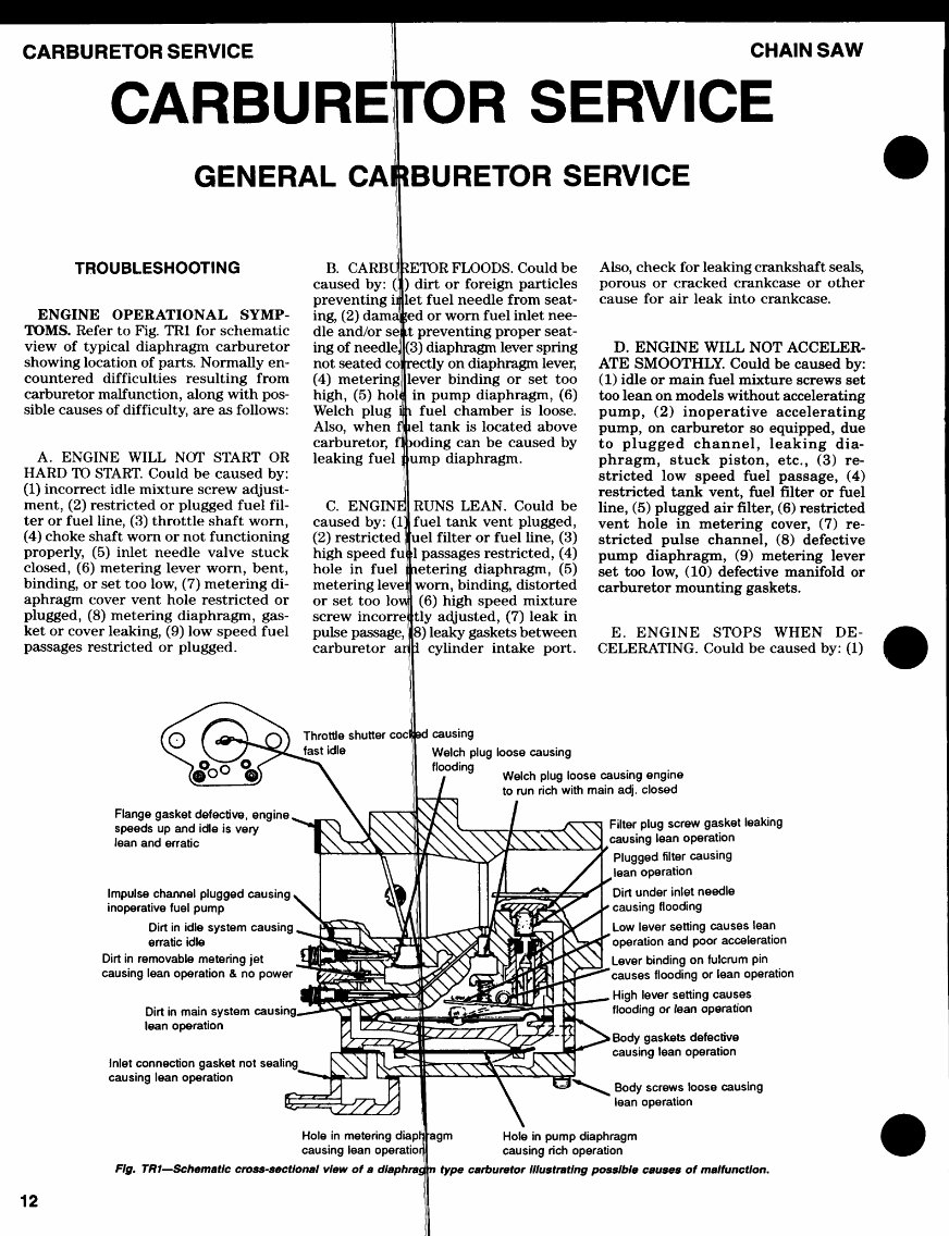
CARBURETOR SERVICE CHAIN SAW CARBURETOR SERVICE GENERAL CARBURETOR SERVICE ENGINE OPERATIONAL SYMP- TOMS. Refer to Fig. TR1 for schematic view of typical diaphragm carburetor showing location of parts. Normally en- countered difficulties resulting from carburetor malfunction, along with pos- sible causes of difficulty, are as follows: A. ENGINE WILL NOT START OR HARD TO START. Could be caused by: (1) incorrect idle mixture screw adjust- ment, (2) restricted or plugged fuel fil- ter or fuel line, (3) throttle shaft worn, (4) choke shaft worn or not functioning properly, (5) inlet needle valve stuck closed, (6) metering lever worn, bent, binding, or set too low, (7) metering di- aphragm cover vent hole restricted or plugged, (8) metering diaphragm, gas- ket or cover leaking, (9) low speed fuel passages restricted or plugged. B. GARB caused by: ( preventing i ing, (2) dam die and/or s ing of needle, not seated c (4) metering high, (5) hoi Welch plug Also, when carburetor, leaking fuel :ETOR FLOODS. Could be I) dirt or foreign particles |let fuel needle from seat- led or worn fuel inlet nee- it preventing proper seat- '3) diaphragm lever spring ;ly on diaphragm lever, |lever binding or set too in pump diaphragm, (6) fuel chamber is loose, icl tank is located above •ding can be caused by lump diaphragm. C. ENGIN1 caused by: (1] (2) restricted high speed fuj hole in fuel metering level or set too loi screw incorrei pulse passage, carburetor ai RUNS LEAN. Could be fuel tank vent plugged, [uel filter or fuel line, (3) 1 passages restricted, (4) .etering diaphragm, (5) worn, binding, distorted (6) high speed mixture ttly adjusted, (7) leak in |8) leaky gaskets between cylinder intake port. Also, check for leaking crankshaft seals, porous or cracked crankcase or other cause for air leak into crankcase. D. ENGINE WILL NOT ACCELER- ATE SMOOTHLY. Could be caused by: (1) idle or main fuel mixture screws set too lean on models without accelerating pump, (2) inoperative accelerating pump, on carburetor so equipped, due to plugged channel, leaking dia- phragm, stuck piston, etc., (3) re- stricted low speed fuel passage, (4) restricted tank vent, fuel filter or fuel line, (5) plugged air filter, (6) restricted vent hole in metering cover, (7) re- stricted pulse channel, (8) defective pump diaphragm, (9) metering lever set too low, (10) defective manifold or carburetor mounting gaskets. E. ENGINE STOPS WHEN DE- CELERATING. Could be caused by: (1) ;o Flange gasket defective, engine, speeds up and idle is very lean and erratic Throttle shutter coclj fast idle ! causing Welch plug loose causing flooding Welch plug loose causing engine to run rich with main adj. closed Impulse channel plugged causing v inoperative fuel pump >^ Dirt in idle system causing erratic idle Dirt in removable metering jet causing lean operation & no power Dirt in main system causing, lean operation Inlet connection gasket not sealing causing lean operation Filter plug screw gasket leaking causing lean operation Plugged filter causing ,lean operation Dirt under inlet needle causing flooding Low lever setting causes lean operation and poor acceleration Lever binding on fulcrum pin causes flooding or lean operation High lever setting causes flooding or (ean operation > Body gaskets defective causing lean operation Body screws loose causing lean operation Hole in metering diaprj causing lean operatior Fig. TR1—Schematic cross-sectional view of a dlaphras agm Hole in pump diaphragm causing rich operation type carburetor Illustrating possible causes of malfunction. 12
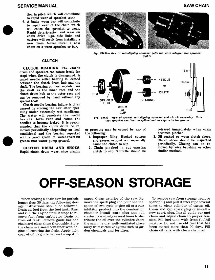
SERVICE MANUAL SAW CHAIN tion in pitch which will contribute to rapid wear of sprocket teeth. 6. A badly worn bar will contribute to rapid wear of the chain which will cause the sprocket to wear. Rapid deterioration and wear on chain drive lugs, side links and cutters will result from installing a new chain. Never install a new chain on a worn sprocket or bar. CLUTCH CLUTCH BEARING. The clutch drum and sprocket can rotate freely (or stop) when the clutch is disengaged. A caged needle roller bearing is located between the clutch drum hub and the shaft. The bearing on most models uses the shaft as the inner race and the clutch drum hub as the outer race and can be removed by hand without any special tools. Clutch needle bearing failure is often caused by storing the saw after oper- ating under extremely wet conditions. The water will penetrate the needle bearing, form rust and cause the needles to become locked. It is recom- mended that the clutch drum be re- moved periodically (depending on local conditions) and the bearing repacked with a good grade of water-resistant grease (not water pump grease). CLUTCH DRUM AND SHOES. Rapid clutch drum wear, shoe glazing Fig. CM31—View of self-aligning sprocket (left) and worn integral star sprocket (right). Bar- RIM Chain— II lirrt Fig. CM32—View of typical self-aligning sprocket and clutch assembly. Note that sprocket can float on spllned hub to align with bar groove. or grooving may be caused by any of the following: 1. Improper filing. Hooked cutters and excessive joint will especially cause the clutch to slip. 2. Chain pinched in cut causing clutch to slip. Throttle should be released immediately when chain becomes pinched. 3. Oil soaked or worn clutch shoes. Clutch shoes should be inspected periodically. Glazing can be re- moved by wire brushing or other similar method. OFF-SEASON STORAGE When storing a chain saw for periods longer than 30 days, the following stor- age instructions should be followed: Drain all fuel from the fuel tank. Start and run the engine until it stops to re- move fuel from carburetor. Drain oil from oil tank. Remove guide bar and chain and clean them thoroughly. Store the chain in a small container with en- gine oil covering the chain. Apply light coat of oil to guide bar and wrap it in paper. Clean exterior of the saw. Re- move the spark plug and pour one tea- spoon of two-cycle engine oil or a rust inhibitor product into the combustion chamber. Install spark plug and pull starter rope slowly several times to dis- tribute the oil over the cylinder. Store the saw in a dry, well-ventilated place away from corrosive agents such as gar- den chemicals and fertilizer. Tb remove saw from storage, remove spark plug and pull starter rope several times to clear cylinder of excess oil. Clean and gap spark plug or install a new spark plug. Install guide bar and chain and adjust chain to proper ten- sion. Fill fuel tank with fresh fuel/oil mixture. Do not use old fuel that has been stored more than 90 days. Fill chain oil tank with clean chain oil. 11
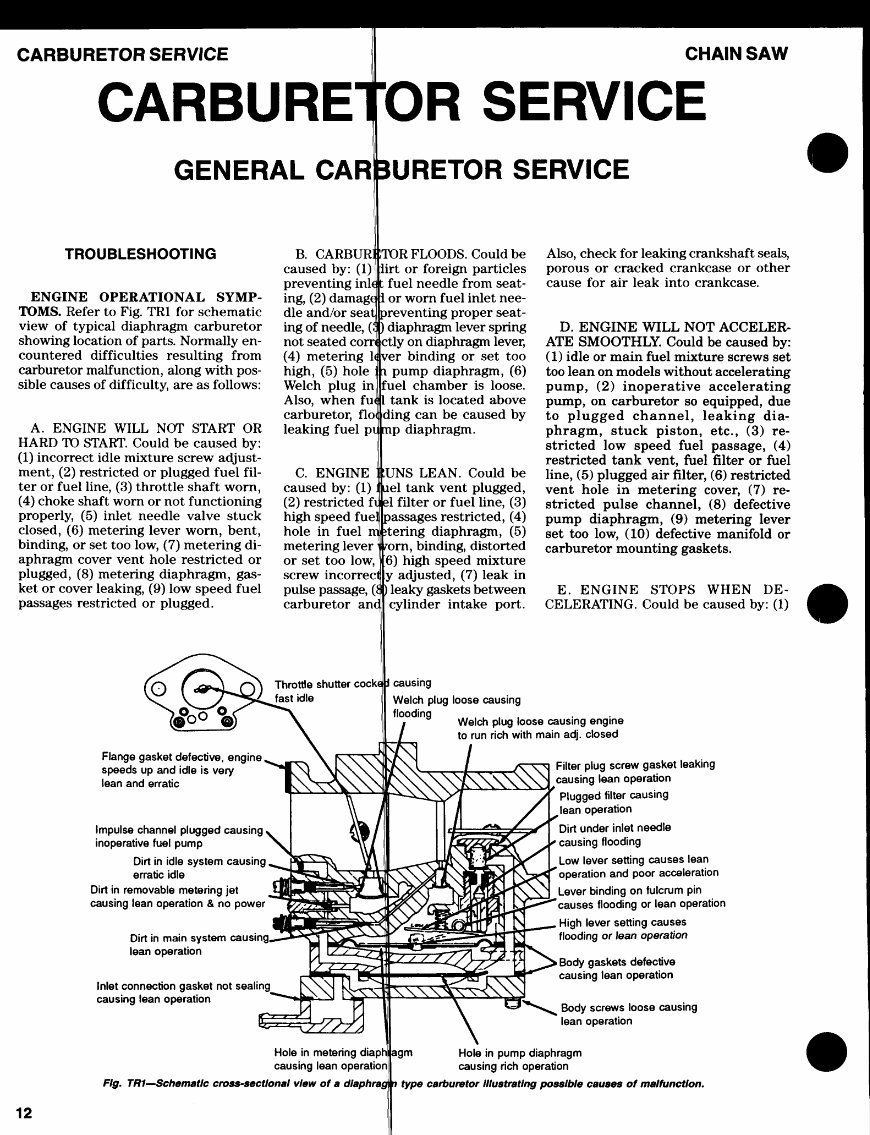
CARBURETOR SERVICE CHAIN SAW CARBURETOR SERVICE TROUBLESHOOTING ENGINE OPERATIONAL SYMP- TOMS. Refer to Fig. TR1 for schematic view of typical diaphragm carburetor showing location of parts. Normally en- countered difficulties resulting from carburetor malfunction, along with pos- sible causes of difficulty, are as follows: A. ENGINE WILL NOT START OR HARD TO START. Could be caused by: (1) incorrect idle mixture screw adjust- ment, (2) restricted or plugged fuel fil- ter or fuel line, (3) throttle shaft worn, (4) choke shaft worn or not functioning properly, (5) inlet needle valve stuck closed, (6) metering lever worn, bent, binding, or set too low, (7) metering di- aphragm cover vent hole restricted or plugged, (8) metering diaphragm, gas- ket or cover leaking, (9) low speed fuel passages restricted or plugged. B. CARBUR] caused by: (1) preventing inl< ing, (2) damag< die and/or seal ing of needle, (J not seated coi (4) metering H high, (5) hole Welch plug in Also, when fu< carburetor, floi leaking fuel pi !TOR FLOODS. Could be irt or foreign particles fuel needle from seat- or worn fuel inlet nee- ireventing proper seat- diaphragm lever spring Jctly on diaphragm lever, jver binding or set too pump diaphragm, (6) Ifuel chamber is loose, tank is located above ding can be caused by p diaphragm. C. ENGINE caused by: (1) (2) restricted fit high speed f hole in fuel metering lever or set too low, screw incorrect pulse passage, (8 carburetor anc :UNS LEAN. Could be iel tank vent plugged, il filter or fuel line, (3) •assages restricted, (4) stering diaphragm, (5) n, binding, distorted high speed mixture [y adjusted, (7) leak in leaky gaskets between cylinder intake port. Also, check for leaking crankshaft seals, porous or cracked crankcase or other cause for air leak into crankcase. D. ENGINE WILL NOT ACCELER- ATE SMOOTHLY. Could be caused by: (1) idle or main fuel mixture screws set too lean on models without accelerating pump, (2) inoperative accelerating pump, on carburetor so equipped, due to plugged channel, leaking dia- phragm, stuck piston, etc., (3) re- stricted low speed fuel passage, (4) restricted tank vent, fuel filter or fuel line, (5) plugged air filter, (6) restricted vent hole in metering cover, (7) re- stricted pulse channel, (8) defective pump diaphragm, (9) metering lever set too low, (10) defective manifold or carburetor mounting gaskets. E. ENGINE STOPS WHEN DE- CELERATING. Could be caused by: (1) ;o Throttle shutter cocke fast idle ! causing Welch plug loose causing flooding Welch plug loose causing engine to run rich with main adj. closed Flange gasket defective, engine, speeds up and idle is very lean and erratic Impulse channel plugged causing. inoperative fuel pump Dirt in idle system causing. erratic idle Dirt in removable metering jet causing lean operation & no power Dirt in main system causinc lean operation Inlet connection gasket not sealing causing lean operation Hole in metering diapti causing lean operation| Fig. TR1—Schematic cross-sectional view of a dlaphr Filter plug screw gasket leaking causing lean operation Plugged filter causing lean operation Dirt under inlet needle causing flooding Low lever setting causes lean operation and poor acceleration Lever binding on fulcrum pin causes flooding or lean operation High lever setting causes flooding or lean operation Body gaskets defective causing lean operation Body screws loose causing lean operation igm Hole in pump diaphragm causing rich operation type carburetor Illustrating possible causes of malfunction. 12
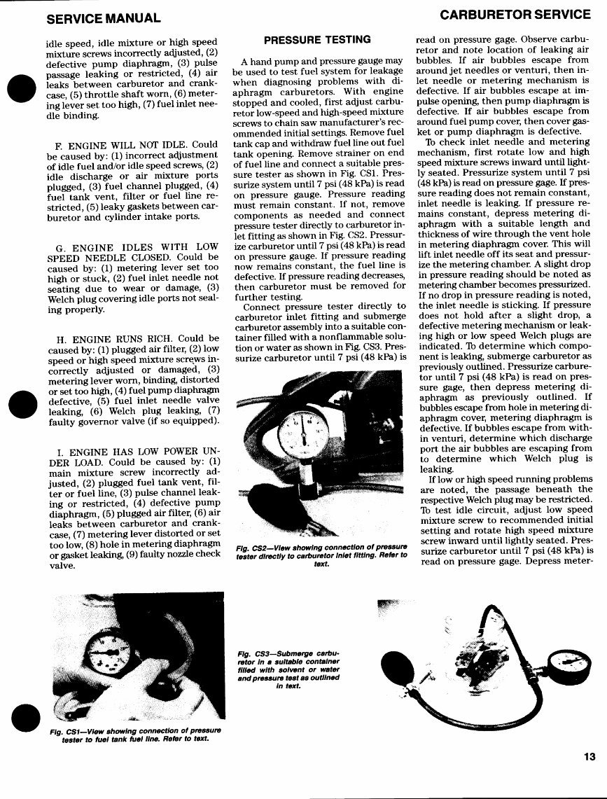
SERVICE MANUAL CARBURETOR SERVICE idle speed, idle mixture or high speed mixture screws incorrectly adjusted, (2) defective pump diaphragm, (3) pulse passage leaking or restricted, (4) air leaks between carburetor and crank- case, (5) throttle shaft worn, (6) meter- ing lever set too high, (7) fuel inlet nee- dle binding. F. ENGINE WILL NOT IDLE. Could be caused by: (1) incorrect adjustment of idle fuel and/or idle speed screws, (2) idle discharge or air mixture ports plugged, (3) fuel channel plugged, (4) fuel tank vent, filter or fuel line re- stricted, (5) leaky gaskets between car- buretor and cylinder intake ports. G. ENGINE IDLES WITH LOW SPEED NEEDLE CLOSED. Could be caused by: (1) metering lever set too high or stuck, (2) fuel inlet needle not seating due to wear or damage, (3) Welch plug covering idle ports not seal- ing properly. H. ENGINE RUNS RICH. Could be caused by: (1) plugged air filter, (2) low speed or high speed mixture screws in- correctly adjusted or damaged, (3) metering lever worn, binding, distorted or set too high, (4) fuel pump diaphragm defective, (5) fuel inlet needle valve leaking, (6) Welch plug leaking, (7) faulty governor valve (if so equipped). I. ENGINE HAS LOW POWER UN- DER LOAD. Could be caused by: (1) main mixture screw incorrectly ad- justed, (2) plugged fuel tank vent, fil- ter or fuel line, (3) pulse channel leak- ing or restricted, (4) defective pump diaphragm, (5) plugged air filter, (6) air leaks between carburetor and crank- case, (7) metering lever distorted or set too low, (8) hole in metering diaphragm or gasket leaking, (9) faulty nozzle check valve. PRESSURE TESTING A hand pump and pressure gauge may be used to test fuel system for leakage when diagnosing problems with di- aphragm carburetors. With engine stopped and cooled, first adjust carbu- retor low-speed and high-speed mixture screws to chain saw manufacturer's rec- ommended initial settings. Remove fuel tank cap and withdraw fuel line out fuel tank opening. Remove strainer on end of fuel line and connect a suitable pres- sure tester as shown in Fig. CS1. Pres- surize system until 7 psi (48 kPa) is read on pressure gauge. Pressure reading must remain constant. If not, remove components as needed and connect pressure tester directly to carburetor in- let fitting as shown in Fig. CS2. Pressur- ize carburetor until 7 psi (48 kPa) is read on pressure gauge. If pressure reading now remains constant, the fuel line is defective. If pressure reading decreases, then carburetor must be removed for further testing. Connect pressure tester directly to carburetor inlet fitting and submerge carburetor assembly into a suitable con- tainer filled with a nonflammable solu- tion or water as shown in Fig. CS3. Pres- surize carburetor until 7 psi (48 kPa) is Fig. CS2—Vlew showing connection of pressure tester directly to carburetor Inlet fitting. Refer to text. read on pressure gage. Observe carbu- retor and note location of leaking air bubbles. If air bubbles escape from around jet needles or venturi, then in- let needle or metering mechanism is defective. If air bubbles escape at im- pulse opening, then pump diaphragm is defective. If air bubbles escape from around fuel pump cover, then cover gas- ket or pump diaphragm is defective. To check inlet needle and metering mechanism, first rotate low and high speed mixture screws inward until light- ly seated. Pressurize system until 7 psi (48 kPa) is read on pressure gage. If pres- sure reading does not remain constant, inlet needle is leaking. If pressure re- mains constant, depress metering di- aphragm with a suitable length and thickness of wire through the vent hole in metering diaphragm cover. This will lift inlet needle off its seat and pressur- ize the metering chamber. A slight drop in pressure reading should be noted as metering chamber becomes pressurized. If no drop in pressure reading is noted, the inlet needle is sticking. If pressure does not hold after a slight drop, a defective metering mechanism or leak- ing high or low speed Welch plugs are indicated. To determine which compo- nent is leaking, submerge carburetor as previously outlined. Pressurize carbure- tor until 7 psi (48 kPa) is read on pres- sure gage, then depress metering di- aphragm as previously outlined. If bubbles escape from hole in metering di- aphragm cover, metering diaphragm is defective. If bubbles escape from with- in venturi, determine which discharge port the air bubbles are escaping from to determine which Welch plug is leaking. If low or high speed running problems are noted, the passage beneath the respective Welch plug may be restricted. To test idle circuit, adjust low speed mixture screw to recommended initial setting and rotate high speed mixture screw inward until lightly seated. Pres- surize carburetor until 7 psi (48 kPa) is read on pressure gage. Depress meter- Flg. CS3—Submerge carbu- retor In a suitable container filled with solvent or water and pressure test as outlined In text. Fig. CS1—Vlew showing connection of pressure tester to fuel tank fuel line. Refer to text. 13
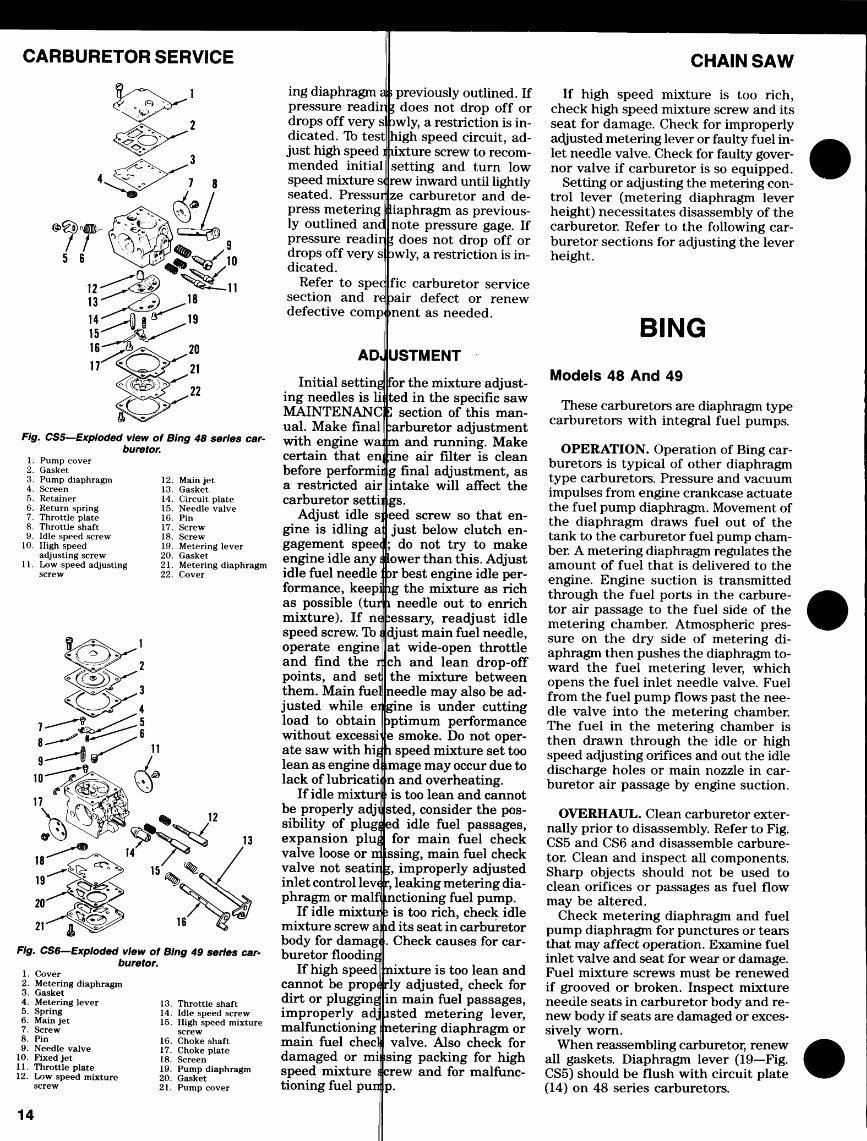
CARBURETOR SERVICE |^\^ r^^*^ ^^X"" ^^ 4 -$^ ^x?^. 6—^*b,"^^ f t v^Y/ s 6 ^ >fr v u s. Jslx1^ ^^-^&g) 1 £ ^r*^^i*~^^~2^ u^jfrlr1 ^^^*\* s 15^>^ 16 ^^=\5 x^"^ S^J_^ , ^^f^ I >^ ^3 / / ^M / \n *n -j^ g 4^^&/ ^^^w 18 '^19 K'! r» F/g. CSS— Exploded view of Bing 48 series car- buretor. 1. Pump cover 2. Gasket 3. Pump diaphragm 4. Screen 5. Retainer 6. Return spring 7. Throttle plate 8. Throttle shaft 9. Idle speed screw 10. High speed adjusting screw 11. Low speed adjusting screw fx^-^N^.1 < ^§=^^ < ^ 2 <C^'®^TV'^ XT^'TN^ 7^-—^SS'^^5 ^-X'^'^'^x' 6 8 ^-"Hfl c*^^ ^ 9-^^J^» / 10 ^~^§S^\f ^ v^S^St-^v ^^ 17 \i Vv^j^^^t «Tv3 ^^Jr^ ^^ •^^^'' 3 \4 18 ^^T' 3 ^^ 15 19 x^^C^ ^^^o^ <£*r§^?Sv 21 ""jir^ll^^ * 12. Main jet 13. Gasket 14. Circuit plate 15. Needle valve 16. Pin 17. Screw 18. Screw 19. Metering lever 20. Gasket 21. Metering diaphragm 22. Cover ^<*!&^ / 2 Vo4 13 /« / *% / ^w ^^C ^^v^^ /\X_^Sr 16 ^ F/g. CS6—Exploded view of Bing 49 series car- buretor. 1 . Cover 2. Metering diaphragm 3. Gasket 4. Metering lever 5. Spring 6. Main jet 7. Screw 8. Pin 9. Needle valve 10. Fixed jet 11. Throttle plate 12. Low speed mixture screw 14 13. Throttle shaft 14. Idle speed screw 15. High speed mixture screw 16. Choke shaft 17. Choke plate 18. Screen 19. Pump diaphragm 20. Gasket 21. Pump cover ing diaphragm a pressure readir drops off very s dicated. To test just high speed mended initial speed mixture s seated. Pressur press metering ly outlined anc pressure readir drops off very s dicated. Refer to spec section and re defective comp AD, Initial setting ing needles is li MAINTENANC ual. Make final with engine wa: certain that en before perform! a restricted air carburetor setti Adjust idle s gine is idling a gagement speet engine idle any i idle fuel needle formance, keepi as possible (tur mixture). If ne speed screw. To < operate engine and find the r points, and set them. Main fuel justed while ei load to obtain without excessr ate saw with hij lean as engine d lack of lubricatii If idle mixtur be properly adji sibility of plugj expansion plug valve loose or rr valve not seatir inlet control lev< phragm or malf If idle mixtui mixture screw a body for damag buretor flooding If high speed cannot be prop* dirt or plugging improperly ad: malfunctioning main fuel checl damaged or mi speed mixture i tioning fuel pun i previously outlined. If I does not drop off or awly, a restriction is in- high speed circuit, ad- lixture screw to recom- setting and turn low rew inward until lightly ze carburetor and de- liaphragm as previous- note pressure gage. If I does not drop off or 3wly, a restriction is in- fic carburetor service rair defect or renew ment as needed. USTMENT for the mixture adjust- ted in the specific saw Z section of this man- :arburetor adjustment m and running. Make ine air filter is clean g final adjustment, as intake will affect the gs. eed screw so that en- just below clutch en- ; do not try to make lower than this. Adjust ar best engine idle per- ig the mixture as rich i needle out to enrich :essary, readjust idle djust main fuel needle, at wide-open throttle ch and lean drop-off the mixture between needle may also be ad- gine is under cutting >ptimum performance e smoke. Do not oper- i speed mixture set too mage may occur due to n and overheating. is too lean and cannot sted, consider the pos- ed idle fuel passages, for main fuel check ssing, main fuel check I, improperly adjusted r, leaking metering dia- nctioning fuel pump. ; is too rich, check idle id its seat in carburetor . Check causes for car- nixture is too lean and rly adjusted, check for in main fuel passages, isted metering lever, netering diaphragm or valve. Also check for ising packing for high crew and for malfunc- P- CHAIN SAW If high speed mixture is too rich, check high speed mixture screw and its seat for damage. Check for improperly adjusted metering lever or faulty fuel in- let needle valve. Check for faulty gover- nor valve if carburetor is so equipped. Setting or adjusting the metering con- trol lever (metering diaphragm lever height) necessitates disassembly of the carburetor. Refer to the following car- buretor sections for adjusting the lever height. BING Models 48 And 49 These carburetors are diaphragm type carburetors with integral fuel pumps. OPERATION. Operation of Bing car- buretors is typical of other diaphragm type carburetors. Pressure and vacuum impulses from engine crankcase actuate the fuel pump diaphragm. Movement of the diaphragm draws fuel out of the tank to the carburetor fuel pump cham- ber. A metering diaphragm regulates the amount of fuel that is delivered to the engine. Engine suction is transmitted through the fuel ports in the carbure- tor air passage to the fuel side of the metering chamber. Atmospheric pres- sure on the dry side of metering di- aphragm then pushes the diaphragm to- ward the fuel metering lever, which opens the fuel inlet needle valve. Fuel from the fuel pump flows past the nee- dle valve into the metering chamber. The fuel in the metering chamber is then drawn through the idle or high speed adjusting orifices and out the idle discharge holes or main nozzle in car- buretor air passage by engine suction. OVERHAUL. Clean carburetor exter- nally prior to disassembly. Refer to Fig. CSS and CS6 and disassemble carbure- tor. Clean and inspect all components. Sharp objects should not be used to clean orifices or passages as fuel flow may be altered. Check metering diaphragm and fuel pump diaphragm for punctures or tears that may affect operation. Examine fuel inlet valve and seat for wear or damage. Fuel mixture screws must be renewed if grooved or broken. Inspect mixture needle seats in carburetor body and re- new body if seats are damaged or exces- sively worn. When reassembling carburetor, renew all gaskets. Diaphragm lever (19—Fig. CSS) should be flush with circuit plate (14) on 48 series carburetors.
This manual covers all aspects of your Echo chainsaw, including engine repair, carburetor repair, blade changing, blade sharpening, and more.
Whether you are a professional mechanic or a DIY enthusiast, this manual provides comprehensive information to help you maintain and repair your Echo chainsaw.
Securely purchase the manual using your credit card or PayPal through our secure server.



 Lifetime Access




