

LG LFX25976 Refrigerators (LFX25976ST/LFX25976WB/LFX25976SW) OEM Service Manual
What's Included?
Fast Download Speeds
Online & Offline Access
Access PDF Contents & Bookmarks
Full Search Facility
Print one or all pages of your manual
REFRIGERATOR
SERVICE MANUAL
CAUTION
BEFORE SERVICING THE UNIT,
READ THE SAFETY PRECAUTIONS IN THIS MANUAL.
MODEL: LFX25976ST
LFX25976WB
LFX25976SW
COLOR : STAINLESS(ST)
WESTERN BLACK
SUPER WHITE

CONTENTS
- 2 -
SAFETY PRECAUTIONS ....................................................................................................................................................... 2
1. SPECIFICATIONS ............................................................................................................................................................. 3
2. PARTS IDENTIFICATION ................................................................................................................................................. 4
3. DISASSEMBLY ............................................................................................................................................................ 5-16
REMOVING AND REPLACING REFRIGERATOR DOORS ............................................................................................. 5
DOOR ................................................................................................................................................................................ 6
DOOR ALIGNMENT .......................................................................................................................................................... 7
FAN AND FAN MOTOR(EVAPORATOR) ......................................................................................................................... 7
DEFROST CONTROL ASSEMBLY ................................................................................................................................... 7
LAMP ................................................................................................................................................................................. 8
MULTI DUCT ..................................................................................................................................................................... 8
MAIN PWB ......................................................................................................................................................................... 9
DISPENSER ...................................................................................................................................................................... 9
DISPLAY PCB ................................................................................................................................................................... 9
ICE BUTTON ASSEMBLY ................................................................................................................................................. 9
WATER BUTTON ASSMEBLY ........................................................................................................................................ 10
ICE CORNER DOOR REPLACEMENT ........................................................................................................................... 10
ICEMAKER REPLACEMENT ..................................................................................................................................... 10-11
SUB PWB FOR WORKING DISPENSER ....................................................................................................................... 11
CAP DUCT MOTOR REPLACEMENT ............................................................................................................................ 11
HOW TO REMOVE A ICE BIN ........................................................................................................................................ 12
HOW TO INSERT A ICE BIN ........................................................................................................................................... 12
HOW TO REMOVE AND REINSTALL THE PULLOUT DRAWER ............................................................................. 13-14
WATER VALVE DISASSEMBLY METHOD .................................................................................................................... 15
FAN AND FAN MOTOR DISASSEMBLY METHOD ........................................................................................................ 15
PULL OUT DRAWER ...................................................................................................................................................... 16
4. ADJUSTMENT ........................................................................................................................................................... 17-19
COMPRESSOR ................................................................................................................................................................ 17
INTRODUCTION OF E-LINEAR COMPRESSOR ...................................................................................................... 17-19
5. CIRCUIT DIAGRAM ........................................................................................................................................................ 20
6. TROUBLESHOOTING .................................................................................................................................................... 21
7. PCB PICTURE ........................................................................................................................................................... 22-23
8. Troubleshooting With Error Display ....................................................................................................................... 24-32
9. Troubleshooting Without Error Display ................................................................................................................. 33-41
10. Reference .................................................................................................................................................................. 42-47
11. COMPONENT TESTING INFORMATION ................................................................................................................. 48-56
12. TROUBLESHOOTING .............................................................................................................................................. 57-63
13. ICEMAKER OPEARTING AND TROUBLE SHOOTING METHOD ......................................................................... 64-67
14. DESCRIPTION OF FUNCTION & CIRCUIT OF MICOM ........................................................................................... 68-71
SAFETY PRECAUTIONS
Please read the following instructions before servicing your refrigerator.
1. Unplug the power before handling any elctrical componets.
2. Check the rated current, voltage, and capacity.
3. Take caution not to get water near any electrical components.
4. Use exact replacement parts.
5. Remove any objects from the top prior to tilting the product.
1. SPECIFICATIONS
- 3 -
Opaque Drawer Type
Linear
Fin Tube Type
Spiral Condenser
R-134a (140 g)
ISO10 (280 ml)
SHEATH HEATER
LED Module(27)
Bulb Lamp
VEGETABLE TRAY
COMPRESSOR
EVAPORATOR
CONDENSER
REFRIGERANT
LUBRICATING OIL
DEFROSTING DEVICE
REFRIGERATOR
FREEZER
LAMP
ITEMS SPECIFICATIONS
Side Rounded
35 3/
4
X 34 1/
4
X 69 3/
4
(WxDxH) 25cu.ft
324.18 (25cu.ft)
Fan Cooling
Micom Control
Full Automatic
Heater Defrost
Embossed Metal, VCM, Stainless
Bar
ABS Resin
Polyurethane Foam
DOOR DESIGN
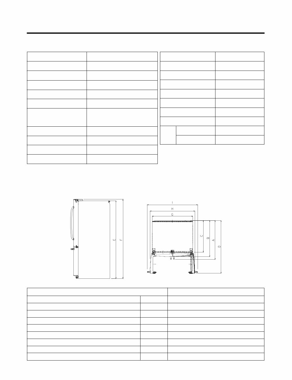
DIMENSIONS (inches)
NET WEIGHT (pounds)
COOLING SYSTEM
TEMPERATURE CONTROL
DEFROSTING SYSTEM
DOOR FINISH
HANDLE TYPE
INNER CASE
INSULATION
ITEMS SPECIFICATIONS
Description LFX25976
Depth w/ Handles
Depth w/o Handles
Depth w/o Door
Depth (Total with Door Open)
Height to Top of Case
Height to Top of Door Hinge
Width
Width (door open 90 deg. w/o handle)
Width (door open 90 deg. w/ handle)
A
B
C
D
E
F
G
H
I
34 1/4 in.
31 3/4 in.
27 7/8 in.
46 1/2 in.
68 3/8 in.
69 3/4 in.
35 3/4 in.
39 1/4 in.
44 1/4 in.
DIMENSIONS
25 cu. ft.
- 4 -
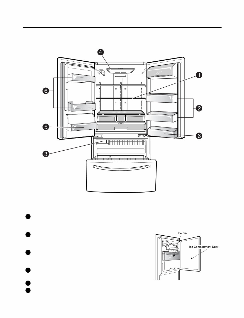
2. PARTS IDENTIFICATION
ADJUSTABLE REFRIGERATOR SHELVING
The refrigerator compartment shelves are adjustable to allow
flexibility for storage needs.
1
GALLON STORAGE BINS
Three interchangeable bins can be arranged to suit your
storage needs.
2
REMOVABLE ICE STORAGE BIN
The ice storage bin can be removed to fill ice buckets,
coolers, or pitchers.
3
LED INTERIOR LAMPS
Refrigerator interior is lit by the LED array.
4
CAN STORAGE BIN 5
FIXED DOOR BINS 6
3. DISASSEMBLY
- 5 -
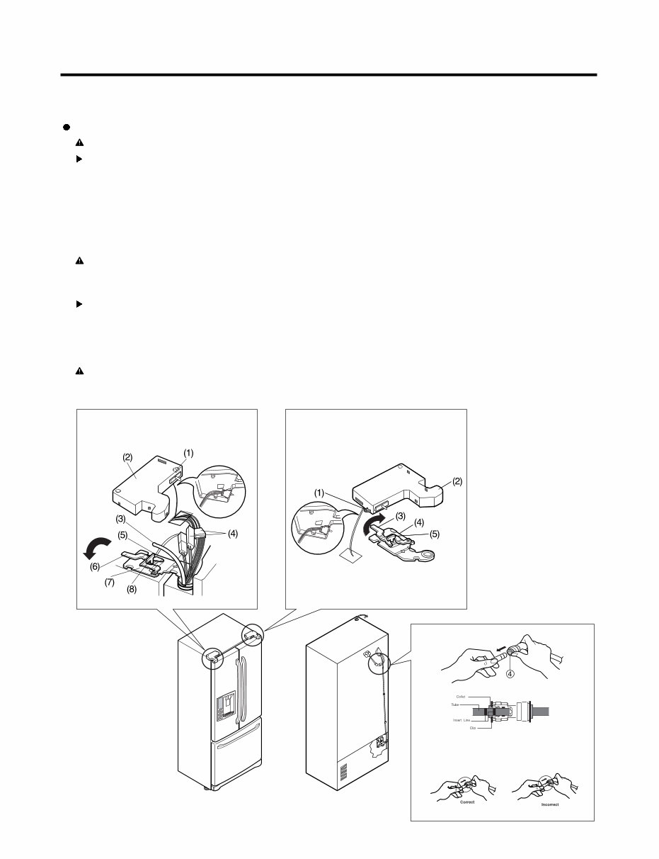
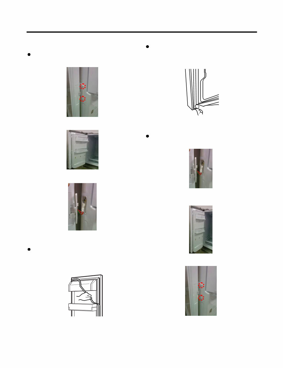
3-1 REMOVING AND REPLACING REFRIGERATOR DOORS
Removing Refrigerator Door
CAUTION: Before you begin, unplug the refrigerator. Remove food and bins from doors.
Left Door -FIG. 2
1. Disconnect water supply tube by pushing back on the disconnect ring (3).-FIG. 1
2. Open door. Loosen top hinge cover screw (1).
Use flat tip screwdriver to pry back hooks on front underside of cover (2). Lift up cover.
3. Disconnect door switch wire harness. Remove cover.
4. Pull out the tube.
5. Disconnect the three wire harnesses (4). Remove the grounding screw (5).
6. Rotate hinge lever (6) counterclockwise. Lift top hinge (7) free of hinge lever latch (8).
7. Lift door from middle hinge pin and remove door.
8. Place door, inside facing up, down onto a non-scratching surface.
CAUTION: When lifting hinge free of latch, be careful that door does not fall forward.
Right Door -FIG. 3
1. Open door. Loosen top hinge cover screw (1). Lift up cover (2).
2. Disconnect door switch wire harness. Remove cover.
3. Rotate hinge lever (3) clockwise. Lift top hinge (4) free of hinge lever latch (5).
4. Lift door from middle hinge pin and remove door.
5. Place door, inside facing up, down onto a non-scratching surface.
CAUTION: When lifting hinge free of latch, be careful that door does not fall forward.
Figure 2 Figure 3
Figure 1
1) Insert the tube until you can see only one of
the lines printed on the tube.
2) After inserting, pull the tube to ascertain that
it is secure.
3) Assemble clip.
- 6 -
1. Remove gasket
Pull gasket free from gasket channel on the four
remaining sides of door.
Figure 3
3-2 DOOR
Pillar Removal
1. Remove 2 screws.
Door Gasket Removal
2. Lift pillar up carefully.
3. Disconnect wire harness.
Door Gasket Replacement
1. Insert gasket into channel
Press gasket into channels on the four remaining
sides of door.
Figure 6
2. Insert pillar into channel.
Inserting pillar assy’ into bracket, door
Pillar Replacement
1. Connect wire harness.
3. Assemble 2 screws.
- 7 -
Figure 8
Figure 9
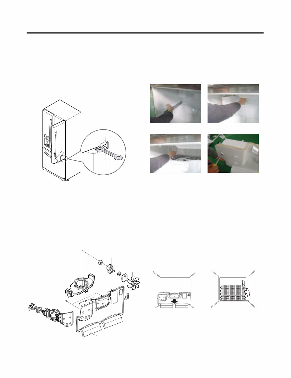
3-3 Door Alignment
If the space between your doors is uneven, follow the
instructions below to align the doors:
Remove the Base Grillie. Turn the leveling legs (CCW) to
raise or (CW) to lower the height of the front of the
refrigerator by using flat blade screw driver or 11/32"
wrench. Use the wrench (Included with the User Manual) to
adjust the bolt in the door hinge to adjust the height. (CCW
to raise or CW to lower the height.)
3-4 FAN AND FAN MOTOR(EVAPORATOR)
1. Remove the freezer shelf. (If your refrigerator has an
icemaker, remove the icemaker first)
2. Remove the plastic guide for slides on left side by
unscrewing phillips head screws.
3. Remove the grille by removing one screw and pulling the
grille forward.
4. Remove the Fan Motor assembly by loosening 2 screws
and disassembling the shroud.
5. Pull out the fan and separate the Fan Motor and Bracket.
BRACKET
MOTOR
GRILLE
FAN
FAN MOTOR
CAUTION
DO NOT ATTEMPT TO REMOVE THE MULLION :
REFRIGERANT LINES!
* Ice Fan Scroll Assembly Replacement
1) Remove the plastic guide for slides on left side by
unscrewing phillips head screws.
2) Pull the grille forward as shown in the second picture.
3) Disconnect wire harness of the grille.
4) Remove the scroll assembly by loosening all screws.
(3) (4)
3-5 DEFROST CONTROL ASSEMBLY
Defrost Control assembly consists of Defrost Sensor and
FUSE-M.
The Defrost Sensor works to defrost automatically. It is
attached to the metal side of the Evaporator and senses its
temperature. At 46°F (8°C), it turns the Defrost Heater off.
Fuse-M is a safety device for preventing over-heating of the
Heater when defrosting.
1. Pull out the grille assembly. (Figure 10)
2. Separate the connector with the Defrost Control
assembly and replace the Defrost Control assembly after
cutting the Tie Wrap. (Figure 11)
Figure 10 Figure 11
GRILLE ASSEMBLY DEFROST-CONTROL
ASSEMBLY
(1) (2)
CAUTION
DO NOT ATTEMPT TO REMOVE THE MULLION :
REFRIGERANT LINES!
- 8 -
Figure 12
Figure 13
Figure 15
Figure 14
Cover, Lamp
LED, Assembly Case Lamp
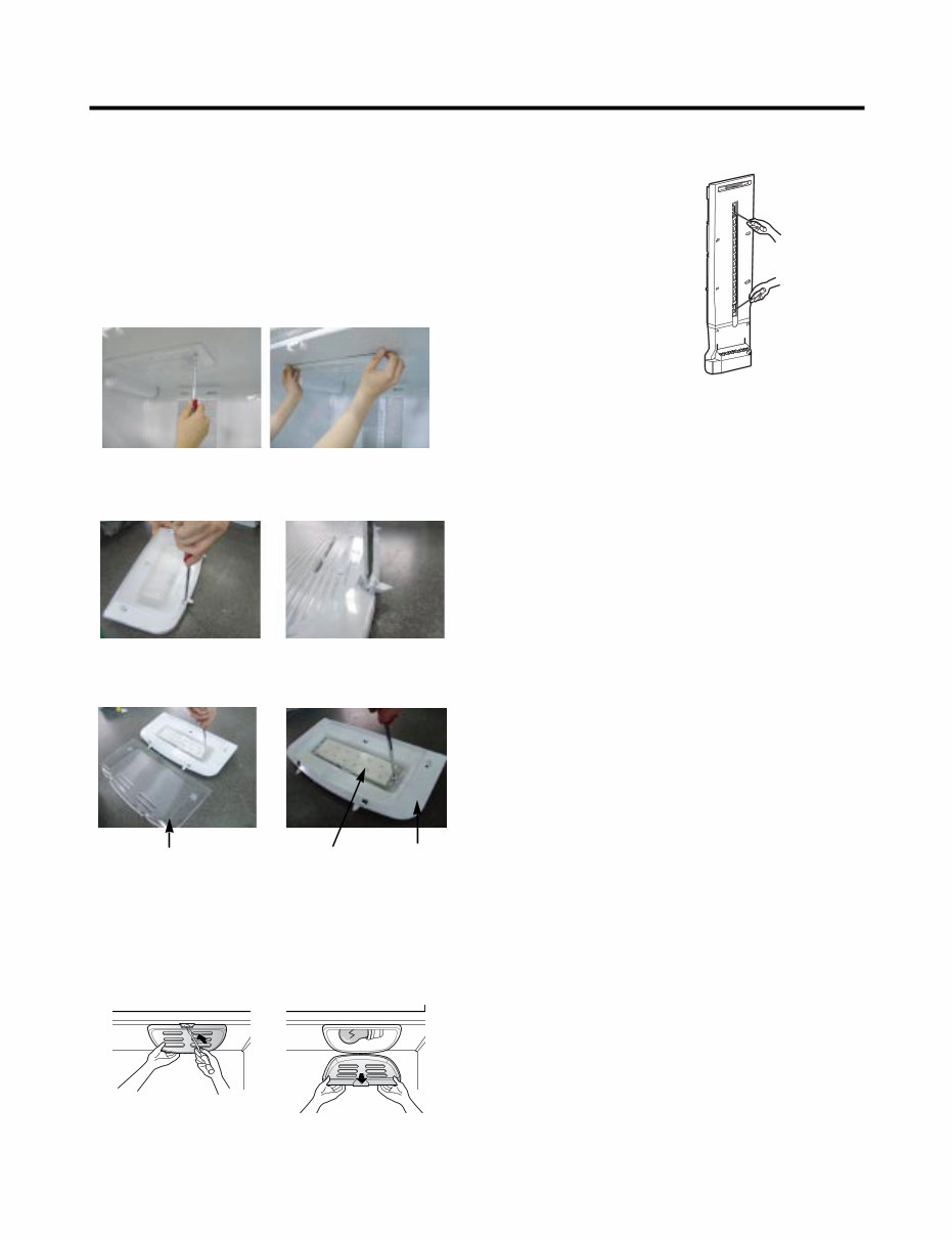
3-6 LAMP
Unplug Refrigerator, or disconnect power at the circuit
breaker.
If necessary, remove top shelf or shelves.
1) Release 2 screws.
2) Hold both ends with your both hands and pull it
downward to remove it.
3) Use a flat tool as shown below to remove
the cover lamp.
3-6-1 Refrigerator Compartment Lamp
1. Unplug refrigerator power cord form outlet.
2. Remove screw with direver.
3. Grasp the cover Lamp,pull the cover downward.
3-6-2 Freezer Compartment Lamp
4) As shown below, use a flat tool to remove the cover
lamp.
3-7 MULTI DUCT
1. Remove the upper and
lower Caps by using a flat
screwdriver, and remove 2
screws. (Figure 16)
2. Disconnect the lead wire
on the bottom position.
Figure 16
- 9 - - 9 -
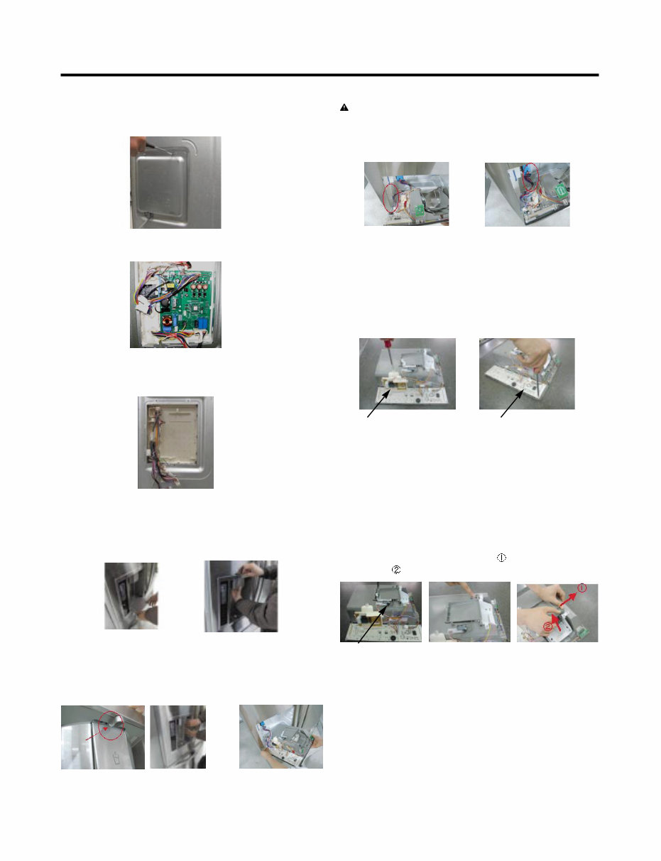
3-8 MAIN PWB
1) Loosen the 3 screws on the PWB cover.
3-9 DISPENSER
1) Pull out the darin 2) Hold the inner side of
cover dispenser with
both hands at the handle
side to pull it out forward.
2) Remove the PWB cover
3) Disconnect wire harness and replace the main PWB in
the reverse order of removal.
3-10 DISPLAY PCB
As shown below, remove 1 case PCB fixing screw.
Remove the display PCB fixing screw.
3-11 ICE BUTTON ASSEMBLY
1) Remove the screw fixing the button lever.
2) Push the spring from the hanging hook to remove it.
3) Apply some pressure to the rib in direction and lift the
button in direction.
3) If nozzle is interfered with button,
push and pull out the bottom of
button.
4) Rmove the
connected part
of Lead wire.
CAUTION: When replacing the dispensor cover in the
reverse order of removal, be careful that the lead wire
does not come out and the water tube is not pinched by
the dispensor.
Case, PCB
Button Lever
Display PCB
- 10 -
3-13 ICE CORNER DOOR REPLACEMENT
1) Loosen the front screw as shown in the picture.
2) Lift up the hinge with one hand.
3) Pull out the Ice Corner Door with the other hand.
3-12 WATER BUTTON ASSMEBLY
1) Romove screws.
2) Grasp the Button assembly and lift up.
Button Lever
hinge
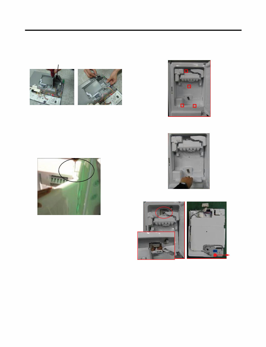
3-14 ICEMAKER REPLACEMENT
1) Remove the stainless screws marked in the picture
below.
2) Grasp the bottom of motor cover assembly and pull it out
slowly.
3) Disconnect wire harness from wall of compartment.
In-door
motor
You're Reading a Preview
What's Included?
Fast Download Speeds
Online & Offline Access
Access PDF Contents & Bookmarks
Full Search Facility
Print one or all pages of your manual
$36.99
$48.99
Viewed 60 Times Today


Secure transaction
What's Included?
Fast Download Speeds
Online & Offline Access
Access PDF Contents & Bookmarks
Full Search Facility
Print one or all pages of your manual
$36.99
$48.99
This OEM service manual for the LG LFX25976 Refrigerators (LFX25976ST, LFX25976WB, LFX25976SW) provides essential technical information for repair and maintenance.
- Safety precautions to be observed during servicing
- Detailed specifications for the refrigerator
- Identification of various parts
- Disassembly instructions
- Adjustment procedures
- Circuit diagram for electrical components
- Troubleshooting guidelines for identifying and resolving issues
- PCB picture for reference
- Troubleshooting methods with and without error display
- Component testing information
- Operating and troubleshooting methods for the icemaker
- Description of function and circuit of MICOM
This manual is available in English and is compatible with both Windows and Mac platforms.


