CAUTION: PLEASE READ THE SAFETY PRECAUTIONS OF THIS MANUAL CAREFULLY BEFORE REPAIRING OR OPERATING THE REFRIGERATOR. REFRIGERATOR SERVICE MANUAL MODELS: LTNC11121V
CONTENTS SAFETY AND SERVICE PRECAUTIONS ........................ ................................................................................................................................................................. .............................................................................................................................................. ..................................................................................................................................................................... ............................................................................................................................................. Removing Refrigerator Door ............................................................................................................................................ ................................................................................................................................................................. ........................................................................................................................................................... ........................................................................................................................................................ ............................................................................................................................................ .......................................................................................................................................................... 4. ADJUSTMENTS ................................................................................................................................................................... .............................................................................................................................................................. ........................................................................................................................................................... ................................................................................................................................ .......................................................................................................................................... ............................................................................................................................................... ........................................................................................................................ Actions for LED blinking and activation current ........................................................................................................... .................................................................................................. 6.7 LED is blinking 7 times.................................................................................................................................................... 6.8 Check compressor and harness ..................................................................................................................................... 6.9 Another electric components .......................................................................................................................................... 6.10 Problem Diagnosis Chart .............................................................................................................................................. 6.11 Refrigeration Cycle ....................................................................................................................................................... 7. COMPRESSOR .................................................................................................................................................................... ........................................................................................... 9. ERRORS ................................................................................................................................................................................ 10. EXPLODED VIEW .............................................................................................................................................................. ...................................................................................................... . 1. SPECIFICATIONS 2. PARTS IDENTIFICATION 3. DISASSEMBLY 3.1 Removing the Freezer Door 3.2 3.3 Switch............. 3.4 Fan & Fan Motor .. 3.5 Refrigerator Lamp ... 3.6 Control Panel Disassembly . 3.7 PCB Disassembly . 5. CIRCUIT DIAGRAM 6.TROUBLESHOOTING 6.1 Compressor activation defect ......... 6.2 Compressor service manual . 6.3 Simple verification order .. 6.4 Actions for each number of LED blinking 6.5 ... 6.6 Activation current and LED blinking 6 times ................. 8. DESCRIPTION AND FUNCTION OF ELECTRONIC CIRCUIT 3 5 6 7 7 7 7 7 8 8 8 9 11 12 12 13 13 14 14 15 16 17 18 19 20 21 22 27 52 2
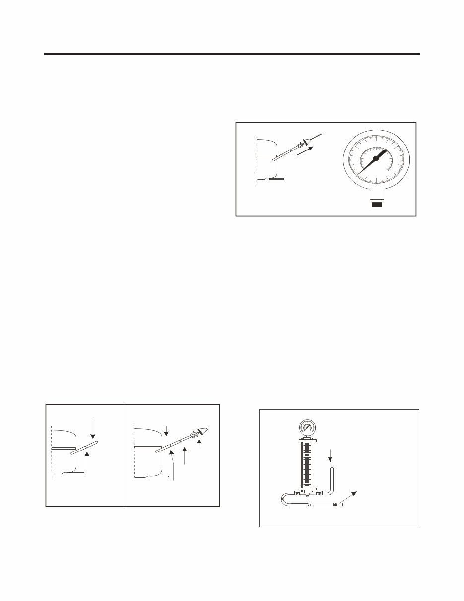
3 Extension tube (load) Con. Hen. Hansen male connector Welding point Service Tube Extension Breaking point Pressure Vacuum pump gauge SAFETY PRECAUTIONS SAFETY AND SERVICE PRECAUTIONS Please read before start your service refrigerator: 1. Disconnect your refrigerator before starting the service in order to prevent electric discharge 2. Check visually there's not a gas leakage or short circuit in the refrigerator. 3. In case of realize tests with the connected refrigerator, use rubber gloves to prevent any accident. 4. If you use any appliance, verify voltage and capacity regularly. 5. Don't touch metallic parts with humid hands, they could be adhered. 6. Make sure there's no water drain to electric or metallic parts 7. When the freezer door is open and you're checking the low part, be careful when you lift your head, you could get 8. Remove all the glasses, metal or other freely parts when you tilt the refrigerator. 9.When servicing the evaporator, wear gloves to prevent injuries from the sharp evaporator fins. The vacuum process to the system starts as soon as the pump starts to work. The refrigerator system must be kept under vacuum until the low pressure meter indicate Absolute 0 or -1 atm, -760 mmhg (see Figure #3). In any case, the pump must not be working for more than 30 minutes. In case of leakage and the vacuum couldn't be realized, it's necessary to apply a small amount of Freon to the system. If the vacuum isn't achieved (the lower pressure meter doesn't indicate Absolute 0 or -1 atm, -760 mmhg) turn on the refrigerator and try to localize the leakage with a leakage locator. If you identify a welding failure, open the valve to normalize the interior pressure with the same exterior pressure before welding. The molten solder could be suctioned o expelled and block the cycle tubes if the vacuum system isn’t stabilized. As soon as the vacuum process is finished, charge the correct refrigerant R-134a gram amount in the system. Remember, each system use an exact R-134a amount with a tolerance of ±5 grams (see Figure #4). It's necessary to realize the welding process with the opened valve to allow the freely output of gasses from oil. Use a female connector to join the new tube extension and the Hansen connector with the vacuum pump (see Figure #3). SERVICE CAUTIONS Test compressor operation before recharge the refrigerant, this is important in order to detect immediately failures and assure compressor motor reliability. If the failure has been identified, clean possible R-134a remnants' in the system breaking the end of the compressor service tube in the thinnest part (as shown in Figure #1). Change the filter and any other damaged part. Disjoint and pull away the rest of the service tube. Put a new tube extension in the Hansen male connector. Weld the new tube (See Figure #2). Refrigerant Charge to Compressor Refrigeration System Cylinder of R-134a Figure # 4 hurt. Figure # 1 Figure # 2 Figure # 3
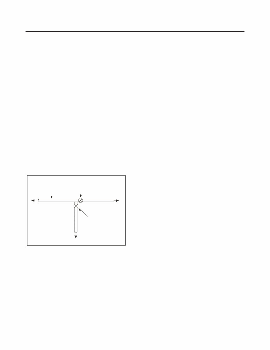
4 Vacuum pump Valve must be closed after achieving a vacuum Charging the cylinder Refrigerator system Refrigerant Loading tube Valve should be open when refilling the gas Figure # 5 To know the refrigerant amount that contains and that it’s necessary to be charged to the system, review the graduated scale cylinder. For example, if we have 750 grams Freon in the cylinder and we must charge 165 grams to the system, this amount will be reached when the cylinder indicator shows 585 grams. Remember that the charge indicator shows a lower lever than real. Do this after select the scale that corresponds to gas pressure indicated in the pressure meter attached in the column upper part. Before performing this operation, make sure that the valve attached between the vacuum pump and recharge cylinder is closed in order to keep the Freon to be charged into the system (see Figure #5). To make R-134a flow to the system, open the valve which is attached in the cylinder base and is connected to the filling tube. The Freon gas amount must not be completely charged in one session because it could block the compressor motor; therefore, charge 20~30 grams and immediately close the valve, the pressure increase and the compressor motor start the suction, this make pressure decrease, open the valve again and repeat the previous steps until rise the established amount of R-134a gas for the system. When the system is under operation, the suction pressure must stabilize between 0.30 and 0.6 atmosphere of pressure.
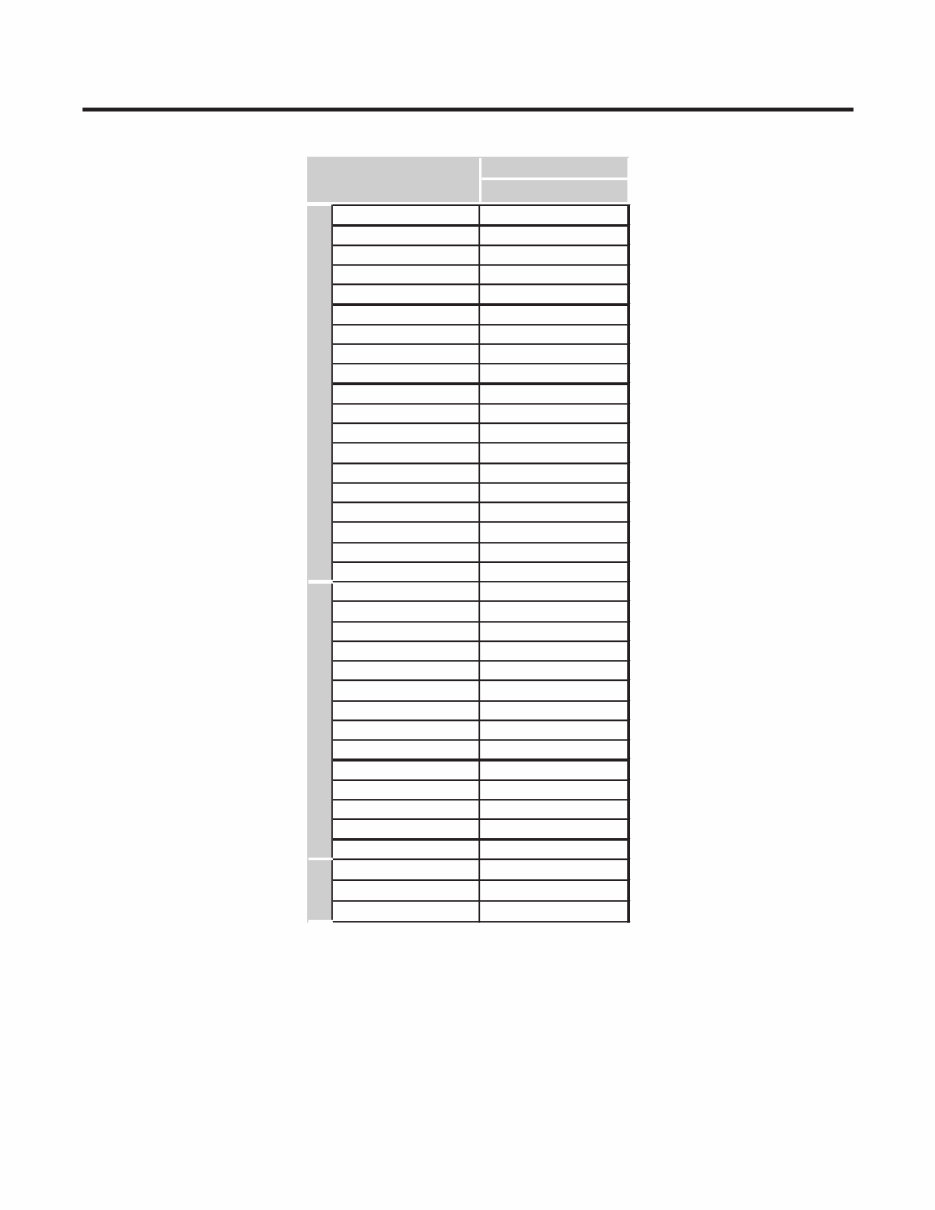
1. SPECIFICATIONS 5 MODEL LTNC11121V Platinum Silver 3 24 (W) x 26 (D) x 66 1/2 (H) 56,2 Kg 11.1 R134a (131 gr) Template (N) 115V/60Hz Fan Cooling MICOM Control Heater Defrost Cyclo Pentanane BLDC Inverter Fin Tube W ire Molecular Sieve XH-7 ID Ø 0. 67 4 Hours 7-40 Hours Heater, Sheath PCM (Normal) PET Pocket Handle LG 2 full + 2 half "Twist" type Yes (LED) 2 Glass + 1 Pull Out Yes (1) No Yes Yes (1) No No 2 full No Glass (1) GENERAL FEATURES Color Dimensions (in) Net Weight Capacity (cu ft) Cooling System Temperature Control Defrosting System Refrigerant Climate Class Rating Condenser Drier Capillary Tube Ins ulation Compressor Evaporator Door material Handle Type Internal Graphics Basket First Defrost Ciclo de Deshielo Defrost Cycle SPECIFICATIONS FREEZER Basket Lamp Shelf Egg Tray Hygiene Filter Water Dispenser Vegetable Drawer Meat Tray Cover TV (Tray Vegetable) Ice Tray Lamp Shelf FRIDGE Case Material
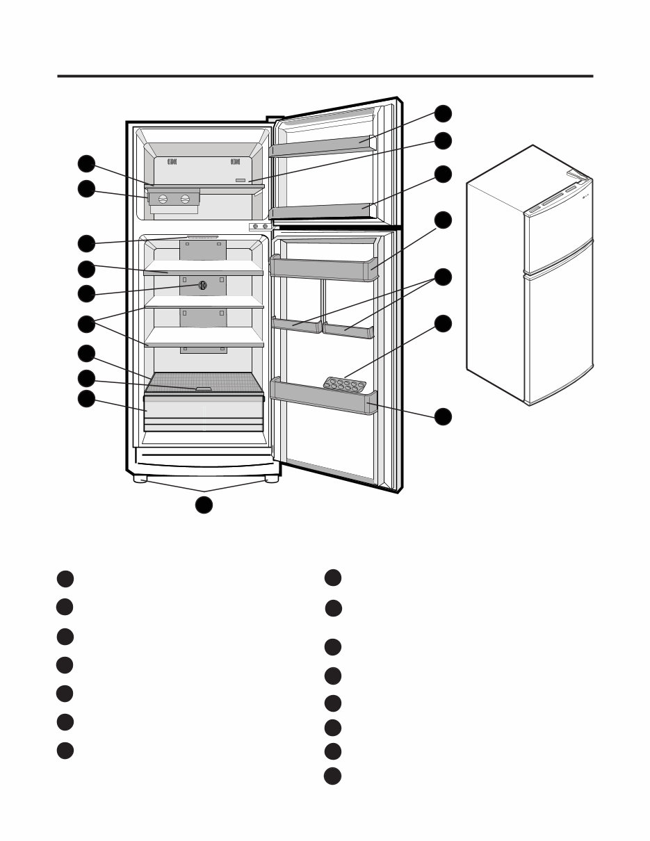
NOTE: Your refrigerator could have some or all of the features and parts listed below. The location of some 2. PARTS IDENTIFICATION A B C F G D E Pull-out Tray I J H M O N M K L I K Sliding Ice Maker (Twist’n Serve) Refrigerator Lamp (LED) Pull-out Tray Refrigerator Temperature Control Refrigerator Shelf (Glass) Magic Crisper (Plastic) Vegetable drawer cover that controls humidity level Humidity Control Vegetable Drawer It keeps vegetables and fruits fresher. Leveling Screws Freezer Basket Freezer Temperature Control Refrigerator Big Basket Refrigerator Small Basket Egg Tray A B C F E D I H J K L M G N O Freezer Shelf (Glass) 6 of the parts may not correspond with your model.
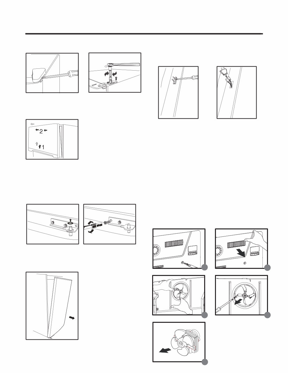
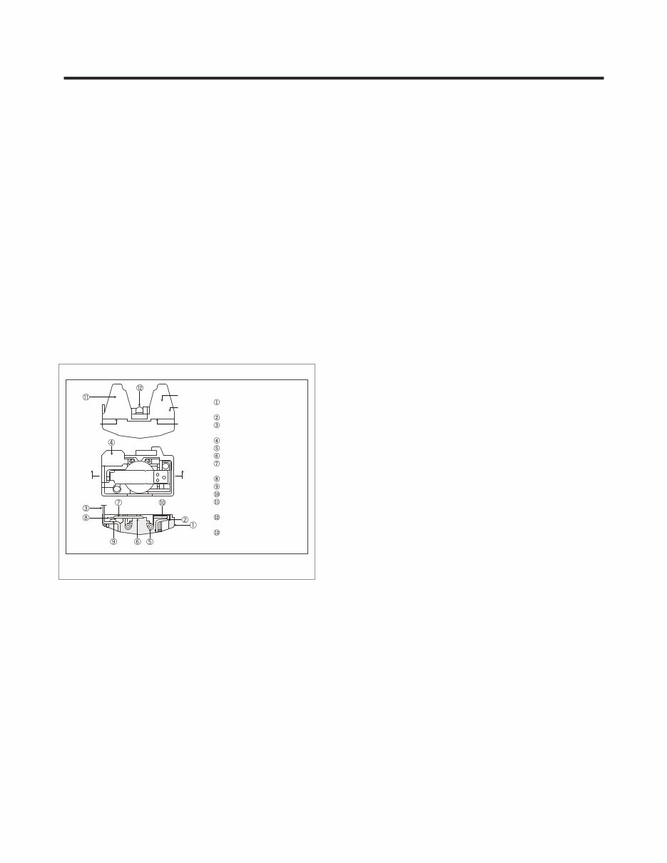
3. DISASSEMBLY 3.1 REMOVING THE FREEZER DOOR NOTE: For assembly the door follow the steps in order 3, 2 and 1. 1. Using a flat screwdriver remove the hinge cover placed in the right upper side. 2. Loose and remove the bolts using a hex socket wrench, then remove the hinge. 3. Carefully lift up the freezer door (1) and place it on a non-scratching surface (2). 3.2 REMOVING REFRIGERATOR DOOR 2. Loose and remove the bolts using a hex socket wrench, then remove the hinge. 3. Carefully lift up the freezer door and place it on a non- scratching surface. 3.3 DOOR SWITCH 1. To remove the door switch, remove it with a screwdriver as shown in above figure. 2. Disconnect the lead wire from the switch. NOTE: For assembly the door follow the steps in order 3, 2 and 1. 1. Remove the washer from the central hinge. 7 3.4 FAN AND FAN MOTOR ? Remove the shelves from freezer compartment. ? Loose the screw placed in fan grille (use a Phillips screwdriver) u . ? Hold the upper side of the shelf and pull it out carefully v . ? Remove the plastic cover from the fan by pulling it put carefully w . ? Unplug the wires. ? Loose the two screws that hold the motor support and pull it out in order to remove the fan and fan motor x . ? Remove fan from motor support y . 1 2 2 3 4 5
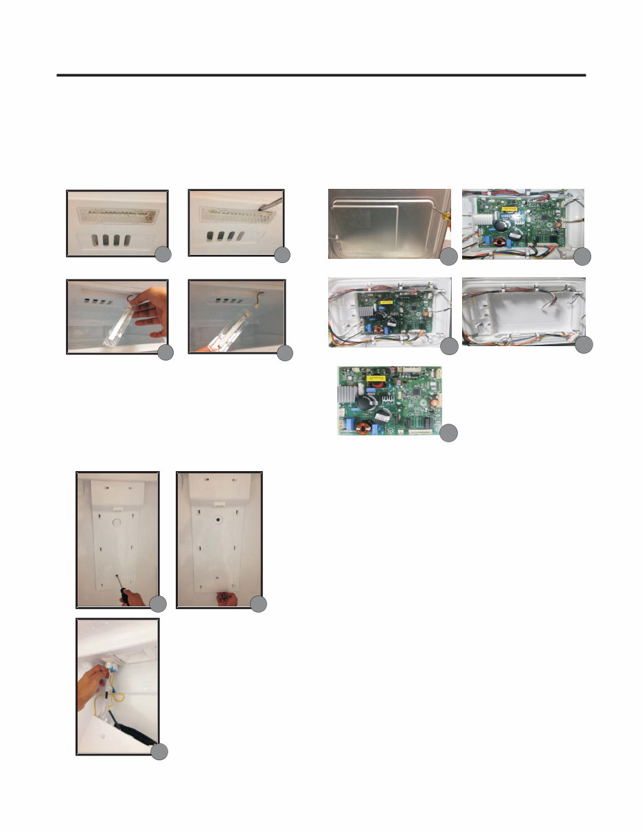
3.5 REFRIGERATOR LAMP ? Identify the lamp that is placed in top side of refrigerator compartment u . ? Use a flat head screwdriver to remove the lamp cover v . ? Press the connector w for releasing LED lamp x . ? To assembly again, follow the steps in order 3, 2 and 1. 1 2 3 4 3.6 CONTROL PANEL DISSASSEMBLY ? Remove refrigerator shelves. ? Loose and remove the screw placed in the lower side of the panel u . ? Take the panel from the lower side and pull it out in order to remove it from refrigerator v . ? Press the connectors to release them w . 1 2 3 8 ? Remove the screws of the cover ? Remove the cover v . ? Disconnect all terminals w . ? Take the PCB out by pressing the hooks of the lower side x . ? If it’s necessary remove and replace the PCB y . u . 3.7 PCB DISASSEMBLY 1 2 3 4 5
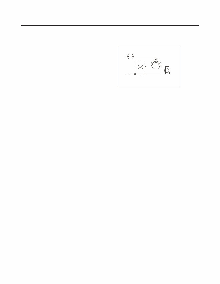
PTC 3 6 S 5 M S M TERMINAL HERMETIC OLP (OVERLOADED PROTECTOR) PTC STARTER RSIR COMPRESSOR 4.1 COMPRESSOR 4.1.1 Function. 4.2.3 PTC- Circuit Diagram Applied. 4. ADJUSTMENTS The compressor sucks evaporated gas in low pressure and lowers the temperature form the evaporator or fridge and compress this gas at high temperature and high pressure and passes it on to the condenser. • According to starting motor method. 4.1.2 Composition. Compressor is made up of a system that compresses the gas, the motor of the compressor and the cover that protects the device. On the exterior of the compressor is found the PTC (thermistor) and the OLP (overload protector). Treat and repair it carefully, because it contains components of processing accuracy of 1/1000 mm and is sealed dust or moisture after manufacture. 4.1.3 Notes for use. (1) Protect your refrigerator of an over voltage or over current. (2) Do not hit: If it’s forced or hit (dropping or careless treatment), Noise can originate or have an inefficient operation. (3) Use appropriate electrical components for the compressor. (4) Note for storing the compressor: If the compressor gets wet during rain and oxidized in the hermetic terminal, may have a poor operation and cause poor contact. (5) Ensure that dust, moisture and soldering flux are not introduced to the compressor during its replacement. Dust, moisture or flux are introduced to the pipe can cause noise or clog it. 4.2.1 PTC Composition (1) The PTC (thermistor) is a semiconductor component that uses starting ceramic material which is composed of BaTiO 3. (2) The higher the temperature, the greater the resistance value. These characteristics are used for engine starting. 4.2 PTC STARTER 4.2.2 PTC Function (1) The PTC is attached to the hermetic compressor and is used for starting the refrigerator compressor. (2) The compressor of a household refrigerator, uses a motor of an induction phase, the normal engine operation is started at the time of starting, the current flows through the auxiliary winding. Once the boot is completed, the current is cut in the auxiliary winding because the PTC is connected in series and this increases its resistance. The characteristics of the PTC have the above functions. Then, the PTC is used as an engine starting system. 4.2.4 Restarting the engine and cooling of the PTC (1) For the restart after power failure during normal operation of the compressor motor, connect the power cord after 5 minutes for the pressure of the refrigeration cycle to stabilize and cool the PTC. (2) During normal operation of the compressor motor, the elements of PTC generate heat continuously. Hence, if the PTC is not coole at some time after power failure, the engine could not operate again. 4.2.5 Relation between the PTC and OLP (1) If your power goes out during operation of the compressor and is reestablished before the PTC has cooled (off in a span of 2 minutes or reconnect the power cord due to a bad connection), the PTC cooling is reached and the resistance value increases. As a result, the current cannot flow to the auxiliary winding and the motor cannot start, because the OLP operates on current flow through the main winding. (3) While the OLP repeat the operation on and off about 3 to 5 times, the PTC cools the compressor and the engine operates normally. If the OLP does not operate when the PTC is hot compressor motor will overheat causing a short circuit or even fire. Then, use a flawless OLP. 4.2.6 Note for Using the PTC-Starter (1) Be careful not to allow over-voltage and over-current. (2) Do not drop or handle carelessly. (3) Keep away from any liquid. If liquid such as oil or water enters the PTC, PTC materials may fail due to breakdown of their insulating capabilities. (4) Do not change the PTC at your own convenience. Do not disassemble the PTC or the mold. Damage to the exterior of the PTC, the resistance value is altered and can cause failures on the compressor motor. Use a PTC in good conditions. 9
4.3 OLP (OVERLOAD PROTECTOR) 4.3.1 Definition of OLP. (1) OLP (OVERLOAD PROTECTOR) is attached to the Compressor and protects the Motor by opening the circuit to the Motor if the temperature rises and activating the bimetal spring in the OLP. (2) When high current flows to the Compressor motor, the Bimetal works by heating the heater inside the OLP, and the OLP protects the Motor by cutting off the current flowing to the Compressor Motor. 4.3.2 OLP Function. (1) The OLP is attached to the compressor and protects the motor by activating the bimetal spring in the OLP, opening the circuit to the motor if the temperature rises. (2) For normal operation of the OLP, do not turn the adjust screw of the OLP in any way. Part Customer part number Lot code/ date code 330 FBYY -S1 BOX98 12345678 Physical termination part number Electrical characteristics part number No. Name Base, phenolic (UL 94 V-0 rated) Movable arm support, plated steel Stationary contact support, plated steel Heater support, plated steel Heater, resistance alloy Disc, thermostatic alloy Movable arm, spring temper copper alloy Contact, movable, silver on copper Contact, stationary, silver on copper Slug, plated steel Cover, polyester (UL 94 V-0 rated) Pin connector, plated copper alloy (To engage 2.33/2.66 mm dia. pin) Quick-connect terminal, brass, conforms to UL 310, MEMA DC-2, DIN 46344 (OVERLOAD PROTECTOR cross section) 10
Is your LG LTNC11121V Refrigerator letting you down?
Why replace while you can upgrade or repair? This service and repair manual is used by the Official Certified LG Technicians. It will help you to troubleshoot and repair your refrigerator!
You will learn about:
Product Specifications
Parts Identification
Disassembly Instructions
Troubleshooting
Adjustment Procedures
Circuit Diagram
Description of Functions & Circuits
Error Codes
Exploded Views
This service manual is very detailed and illustrated with pictures and step-by-step instructions on how to repair/service this device the best way there is!
Please note; this is the OFFICIAL service and repair manual in .PDF format, no scanned-in or bootlegged copy. This manual is made in the highest resolution, so when you print the pages you need it is all in great quality!
You can easily print this manual from any printer and any computer!
INSTANT access! After your payment, you will have instant access to your manual. No shipping fee, no waiting on postal delivery, you can start doing your repairs right away!
Specifications
Language: English
Format: .PDF
Pages: 54
Platform: Windows and MAC
Looking for a service manual but can't find it anywhere? Please contact us with your request! As you can see we've got the largest & most comprehensive service manual database out there, so a good chance we can help you out!