MODELOS: LSC27925SB LSC27925ST LSC27925SW ATENCION: ANTES DE INICIAR EL SERVICIO LEA CUIDADOSAMENTE LAS ADVERTENCIAS DE SEGURIDAD EN ESTE MANUAL. REFRIGERADOR MANUAL DE SERVICIO 9
CONTENTS CONTENTS SAFETY PRECAUTIONS ........................................................................................................ 1. SPECIFICATIONS ............................................................................................................... 2. PARTS IDENTIFICATION .................................................................................................... 3. DISASSEMBLY ................................................................................................................... 1. Door Alignment.................................................................................................................. 2. Install Water Filter.............................................................................................................. 3. Refrigerator Shelves.......................................................................................................... 4. Freezer Shelf..................................................................................................................... 5. How to Control the amount of water supplied to ice maker ................................................ 4. HOW TO DISASSEMBLY AND ASSEMBLY....................................................................... 1. Removing and Replacing Refrigerator door....................................................................... 2. Handle Removal................................................................................................................ 3. How to Remove Swtich Lamp............................................................................................ 4. Fan Shroud Grille............................................................................................................... 5. Ice maker Assembly........................................................................................................... 6. Water Valve Disassembly Method..................................................................................... 7. Water Valve Tubes Assembly Method................................................................................ 8. Disassemble of fan Motor.................................................................................................. 9. Disassemble of Tray Drip................................................................................................... 10. Dispenser........................................................................................................................... 5. MICOM FUNCTION ............................................................................................................. 1. Monitor Panel..................................................................................................................... 6. EXPLANATION FOR MICOM CIRCUIT .............................................................................. 1. Explanation for PCB circuit............................................................................................... 7. ICEMAKER AND DISPENSER WORKING PRINCIPLES AND REPAIR............................ 1. Working Principles............................................................................................................ 2. Function on Icemaker ........................................................................................................ 3. Ice maker Troubleshooting................................................................................................ 4. Icemaker Circuit................................................................................................................ 8. CIRCUIT DIAGRAM............................................................................................................. 9. TROUBLE DIAGNOSIS....................................................................................................... 10. EXPLODED VIEW ..................................... ....................... ................................................. 3 4 5 6 6 7 8 8 9 11 11 12 13 13 14 14 15 16 17 18 20 20 29 29 44 44 45 48 49 50 53 131 - 2 -
- 3 - SAFETY PRECAUTIONS Please read the following instructions before servicing your refrigerator. 1.Check the refrigerator for current leakage. 2.To prevent electric shock,unplug before servicing. 3.Always check line voltage and amperage. 4.Use standard electrical components. 5.Don't touch metal products in the freezer with wet hands.This may cause frost bite. 6.Prevent water from spiling on to electric elements or the machine parts. 7.Before tilting the refrigerator, remove all materials from on or in the refrigerator. 8.When servicing the evaporator, wear gloves to prevent injuries from the sharp evaporator fins. 9.Service on the refrigerator should be performed by a qualified technician.Sealed system repair must be performed by a CFC certified technician.
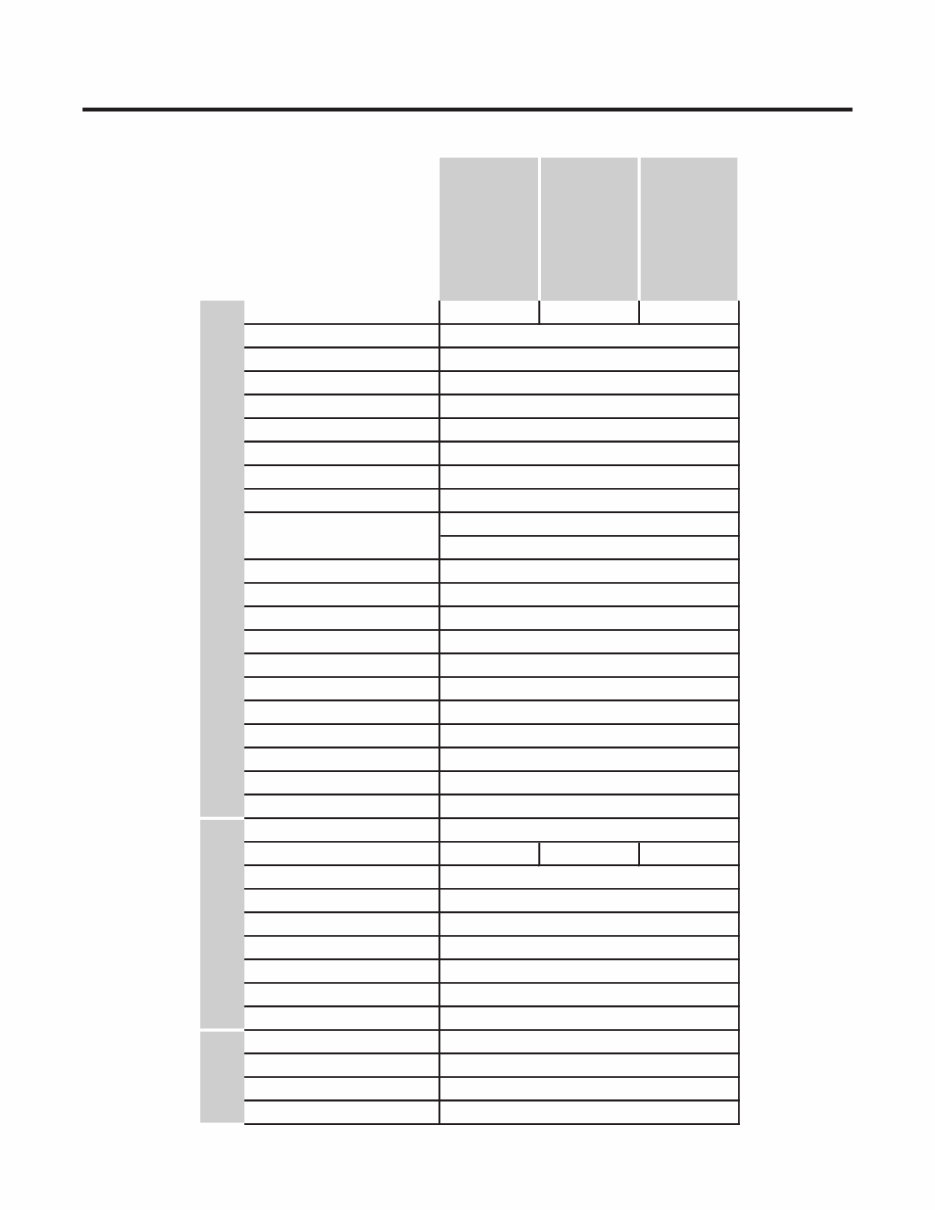
1. SPECIFICATIONS - 4 - LSC27925SB LSC27925ST LSC27925SW Black Stainless Steel Super White PCM Stainless PCM FREEZER Ice Maker Twisting Basket 4 plastic Lamp Yes (1) LED Shelf 3EA (Wire) Shelf 1 (Fix) + 2 (S/Out) Tray meat No Egg Bank No Display Graphic ICE PLUS Basket 4full Lamp Yes (2) LED Desfrosting Device Heater, Sheath Anti-freezing Heater Water Tank Heater REFRIGERATOR Case Material Embo (normal) Door Material Handle Type Vista (AL) Capillary Tube ID Ø0.80 First Defrost 4 Hours Defrost Cycle 13 - 70 Hours Condenser Wire Condenser Lubricanting Oil Polyol Ester (POE) 310 ± 10 cc Drier MOLECULAR SIEVE XH-7 Insulation Cyclo, Pentane Compressor LQ69LAUM PTC Starting Type Evaporator Fin Tube Type Cooling System Fan Cooling Temperature Control MICOM control Defrosting System Full Automatic Heater Defrost Refrigerant R134a Climate class Temperate (N) Rated Rating 115V~ / 60Hz SPECIFICATIONS MODELS GENERAL FEATURES Color Dimensions 36 x 33 x 70 in Net Weight 328.5 lbs Capacity 27 cuft
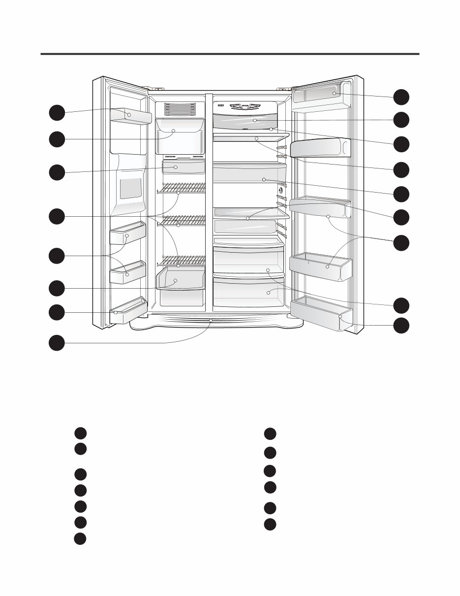
2. PARTS IDENTIFICATION - 5 - A B C D A A E F M G H I J L K H L Use this page to become more familiar with the parts and features. Note: This guide covers several different models.The refrigerator you have purchased may have some or all of the items listed below. The locations of the features shown below may not match your model. Refrigerator Door Rack J L K Refrigerator Shelf Vegetable Drawer I Snack Pan For storage of meat or fresh food. Water Filter H Refrigerator Lamp (LED) M Dairy Corner Drawer B C D A E F G Freezer Door Rack For storage of dairy products such as butter and cheese. Freezer Lamp (LED) Base Grille Freezer Shelf Automatic Icemaker The ice is produced in the icemaker and sent to the dispenser.
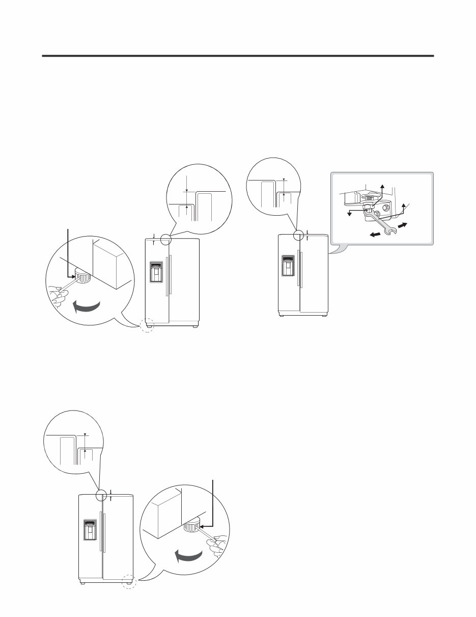
3. HOW TO INSTALL THE REFRIGERATOR - 6 - 1. Before adjusting the doors, remove the Base Grille. If the freezer compartment door is lower than the refrigerator compartment door, make them level by inserting flat blade screwdriver into the groove of the left leveling leg and rotating it clockwise. DOOR ALIGNMENT Left leveling leg Height If the freezer compartment door is higher than the refrigerator compartment door, make them level by inserting flat blade screwdriver into the groove of the right leveling leg and rotating it clockwise. Right leveling leg Height difference Adjust the level when the refrigerator door is lower than the freezer door during the installation of the refrigerator. Tools you need • Wrench 5/16 in (8 mm) • Wrench 3/4 in (19 mm) AFTER LEVELING THE DOOR HEIGHT Make sure the front leveling legs are completely touching the floor. difference Height difference Height difference Height difference Height difference Using a ¾” (19 mm) wrench, turn the keeper nut clockwise to lossen the keeper nut. Keeper nut Adjustment hinge pin Wrench Up Down Using a 5/16” (8 mm) wrench, turn the adjustment hinge pin c refrigerator clockwise or ounter clockwise to level the and After setting the level door, turn the keeper nut counter clockwise to tighten. Do not over tight the door adjustment screw. The hinge pin can be pulled out. (Adjustable range of height is a maximum of ½” (1.27 cm)). freezer door.
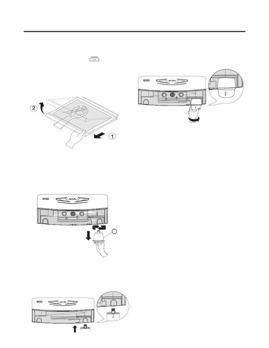
2. INSTALL WATER FILTER - 7 - Before removing or installing water filter: 1. Take out the top shelf and move it to the lowest level. 2. IMPORTANT: Turn off household water supply. • Filter Reset: When the Filter icon turns on, you have to change the water filter. Press the Filter button for 3 seconds to turn the icon . Removing the water filter: 1. Remove old filter by turning it counterclockwise a quarter turn and pulling it down. The substitute cap must be retained for the future. If the filter is removed and not replaced, it is necessary to reinstall the substitute cap to prevent water leaks from the filter housing. A 3. Push the water filter up in to the filter receptacle and rotate it clockwise to lock it into place. Once installed correctly, the lock symbol should be facing you and you should not be able to rotate the filter clockwise anymore. After installing Water Filter 1. Replace the shelf to the initial position. 2. After installing filter, turn on household water supply. 3. Dispense 2.5 gallons (9.46 liters) of water to purge the system, depressing and releasing the dispenser pad in cycles of 30 seconds ON, 60 seconds OFF. Open the refrigerator door and check the shelf area for water leaks. To purchase or replace water filters, call your Service Center. Refer to Warranty Card to obtain the telephone number of the Service Center near you and ask for part no. 5231JA2002A or ADQ72910901. Removing the water filter: 1. Remove the red cap from the filter. 2. Hold the filter with the unlock symbol facing towards you as shown in the figure below. Insert the filter receptacle on the right side of the refrigerator compartment. NOTE: After installation, if you notice that the lock symbol is not facing you or you can continue to rotate the filter clockwise; remove the filter and repeat installation to prevent water leaks.
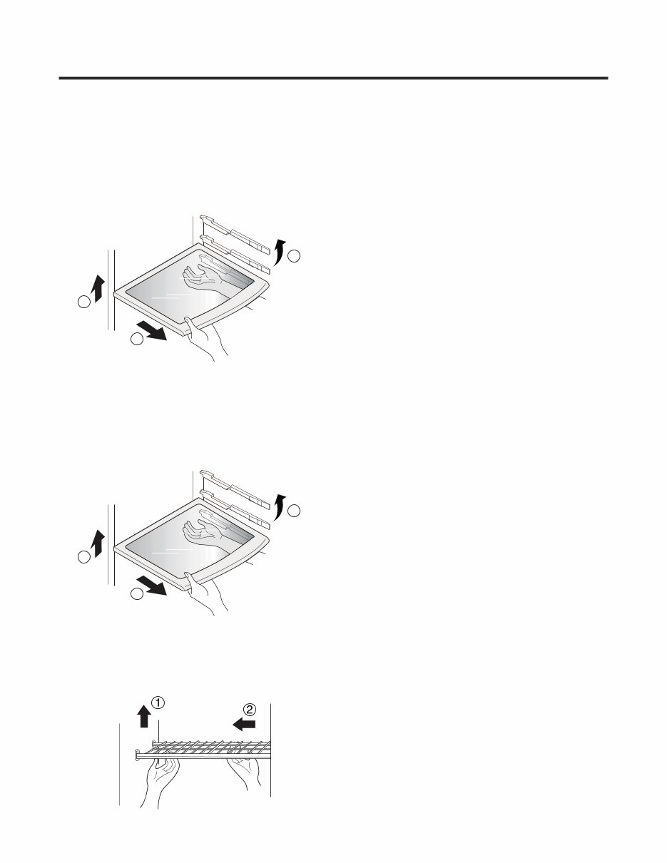
Car e an d Mai n t enance 3. REFRIGERATOR SHELVES you can place it at a height according to space requirement of foods. The refrigerator compartment shelf is adjustable so that • Fixed shelf Lightly lift up the front part of shelf pull it towards you , then take it out while lifting the rear part of shelf . • Slide shelf Pull the shelf head towards you , then lift both front and rear while taking ir out . NOTE: Make sure to keep shelf horizontal while removing; otherwise it may drop. 4. FREEZER SHELF 1 3 2 1 2 3 - 8 - , push the right part to the direction k , and take it out. • Lift the left part of the shelf a bit. Lift it to the direction
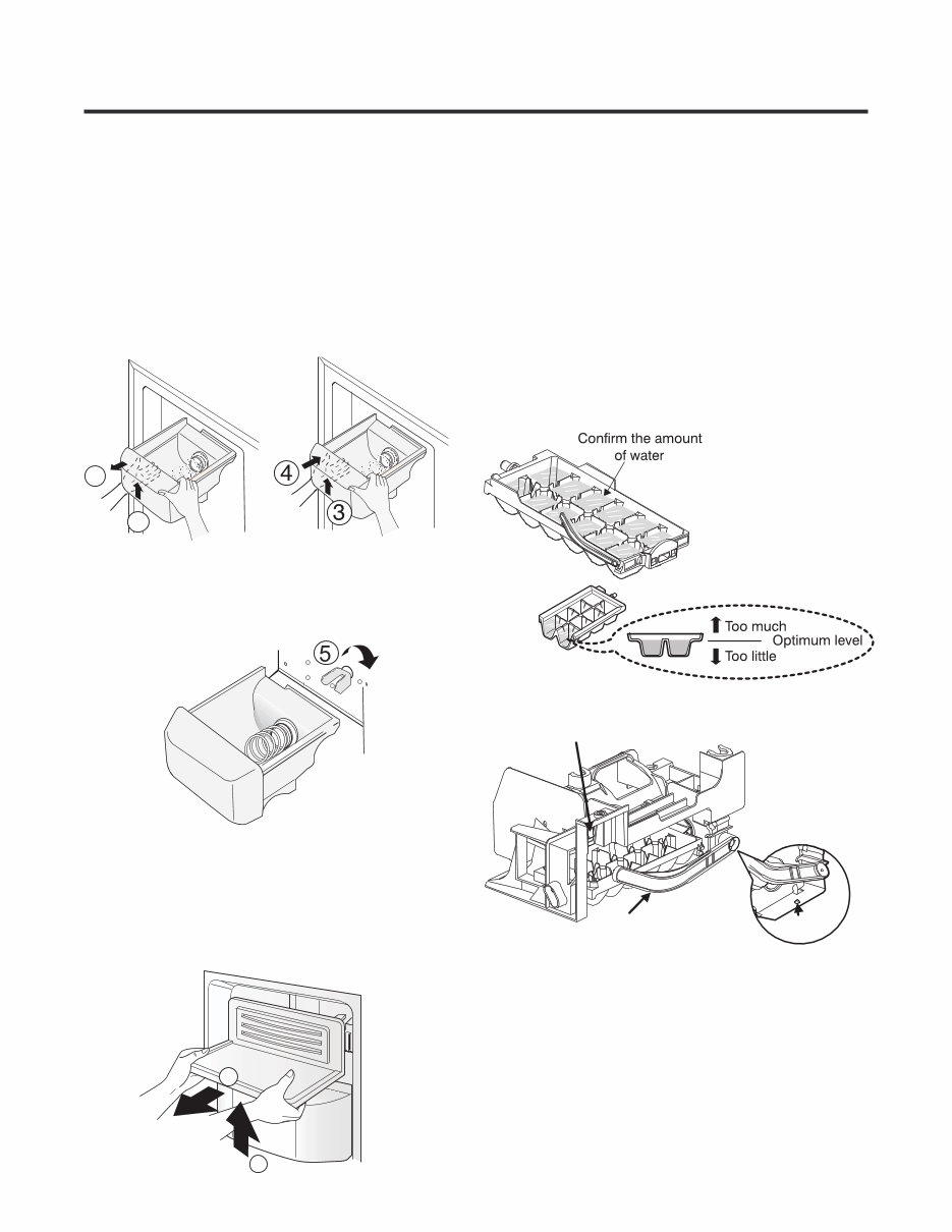
5. HOW TO CONTROL THE AMOUNT OF WATER SUPPLIED TO ICE MAKER 2) Turn on the electricity after connecting water pipe. 1) Press the test switch under the icemaker for two seconds as shown below. 2) The bell rings (ding ~ dong), the ice tray rotates, and water comes out the icemaker water tube. 3) The water is supplied into the tray two or three times. The amount is small each time. Put a container under the ice tray and press test switch. 4) When the ice tray rotates, the water in it will spill. Collect the spilled water and discard it. 5) When ice tray has finished rotation, water comes out the water tube. Check the amount that goes into the ice tray. (Refer to the drawing below. The optimum amount is 110cc. (Almost 4 oz.)). * It is acceptable is the adjusted water level is less than the optimum level. • To assemble the ice storage bin, push it int while slightly lifting it . NOTE: Use both hands to remove the ice bin to avoid dropping it. If the ice bin does not slide into place easily, twist the drive device slightly. • Hold the ice storage bin as shown in the right figure and pull it out while slightly lifting it . 1. DISASSEMBLY ICE STORAGE BIN 1 2 2. DISASSEMBLY ICEMAKER If you need acces to the Icemaker, follow these steps: • Lift the ice shelf as shown in the right figure and pull it out . COVER Feeler Arm Power Switch ON/OFF (On the lower part of icemaker) switch Test - 9 - Make sure it is fully engaged into the auger drive . 1 2
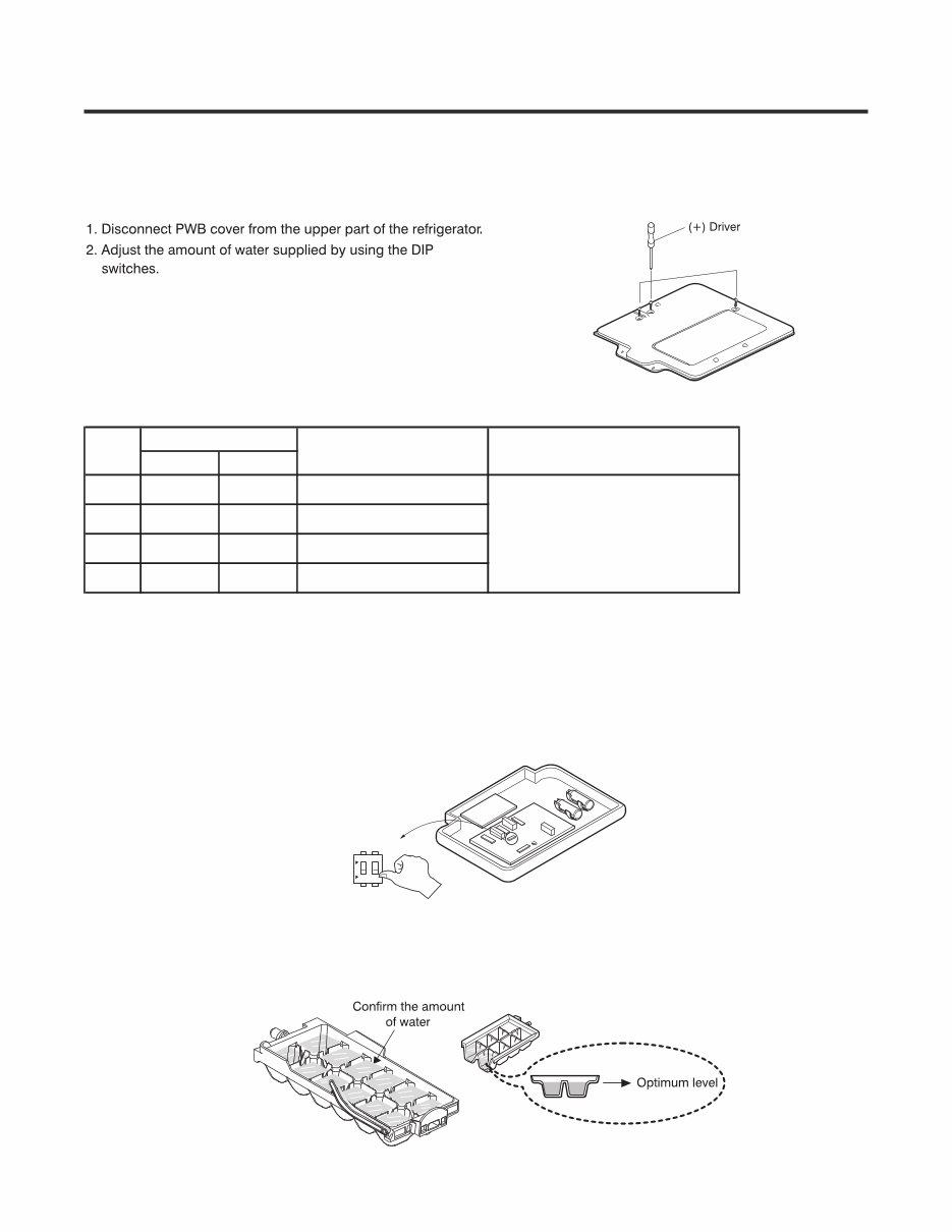
3-2 Control the amount of water supplied to the icemaker. Caution: • Unplug the power cord from the wall outlet and wait at least three minutes before removing the main PWB cover. 310 Volts are present in the control panel. Water Supplying Time Control Option 1) The water supplying time is set at 9s when the refrigerator is delivered. 2) The amount of water supplied depends on the setting time and water pressure (city water pressure). 3) If the ice cubes are too small, increase the water supplying time. This happens when too little water is supplied into the ice tray. 4) If the ice cubes stick together, decrease the water supplying time. This happens when too much water is supplied into the ice tray. Caution: When adjusting the amount of water supplied, adjust step by step. Otherwise the water may spill over. 3. When the adjustment of the control switch for the amount of water supplied is complete, check the level of water in the ice. Switch ON Switch OFF 1 ON 2 - 10 - S1 S2 1 OFF OFF 9.0 2 ON OFF 8.0 3 OFF ON 10.0 4 ON ON 11.0 DIP S/W Setting will be depend of water pressure DISP S/W No Water Supply Time Note
Is your LG LSC27925ST side-by-side refrigerator letting you down?
Why replace when you can upgrade or repair? This service and repair manual is used by Official Certified LG Technicians and will help you troubleshoot and repair your refrigerator. It is useful for both professional mechanics and DIY enthusiasts.
You will learn about:
Product Specifications
Parts Identification
Disassembly and Assembly Instructions
Troubleshooting
Adjustment Procedures
Circuit Diagram
Printed Circuit Board
Test Mode & Diagnostics
Operating & Repair Method of Ice-maker
Description of Function & Circuits
Error Codes
Exploded Views
This service manual is very detailed and illustrated with pictures and step-by-step instructions on how to repair/service this device effectively. Please note that this is the OFFICIAL service and repair manual in .PDF format, not a scanned-in or bootlegged copy. The manual is made in the highest resolution, ensuring great quality when printed. You can easily print this manual from any printer and any computer.
INSTANT access! You will have instant access to your manual with no shipping fee and no waiting on postal delivery, allowing you to start your repairs right away.
Specifications:
Language: English
Format: .PDF
Pages: 138
Platform: Windows and MAC
If you are looking for a service manual that you can't find anywhere, please contact us with your request. We have the largest and most comprehensive service manual database, so there's a good chance we can help you out!