

LG LMXS30776S Service Manual & Repair Guide
What's Included?
Fast Download Speeds
Online & Offline Access
Access PDF Contents & Bookmarks
Full Search Facility
Print one or all pages of your manual
%#76+10
$'(14' 5'48+%+0) 6*' 70+6
4'#& 6*' 5#('6; 24'%#76+105 +0 6*+5 /#07#.
4'(4+)'4#614
5'48+%' /#07#.
Downloaded from www.Manualslib.com manuals search engine
- 2 -
SAFETY PRECATUTIONSS.................................................................................................................................................... 2
1. SPECIFICATIONS ............................................................................................................................................................... 3
2. PARTS IDENTIFICATION.................................................................................................................................................... 4
3. DISASSEMBLY.............................................................................................................................................................. 5-29
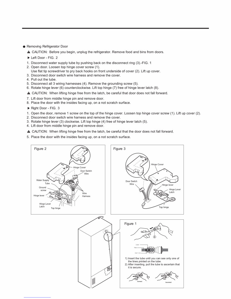
REMOVING AND REPALCING REFRIGERATOR DOORS ............................................................................................... 5
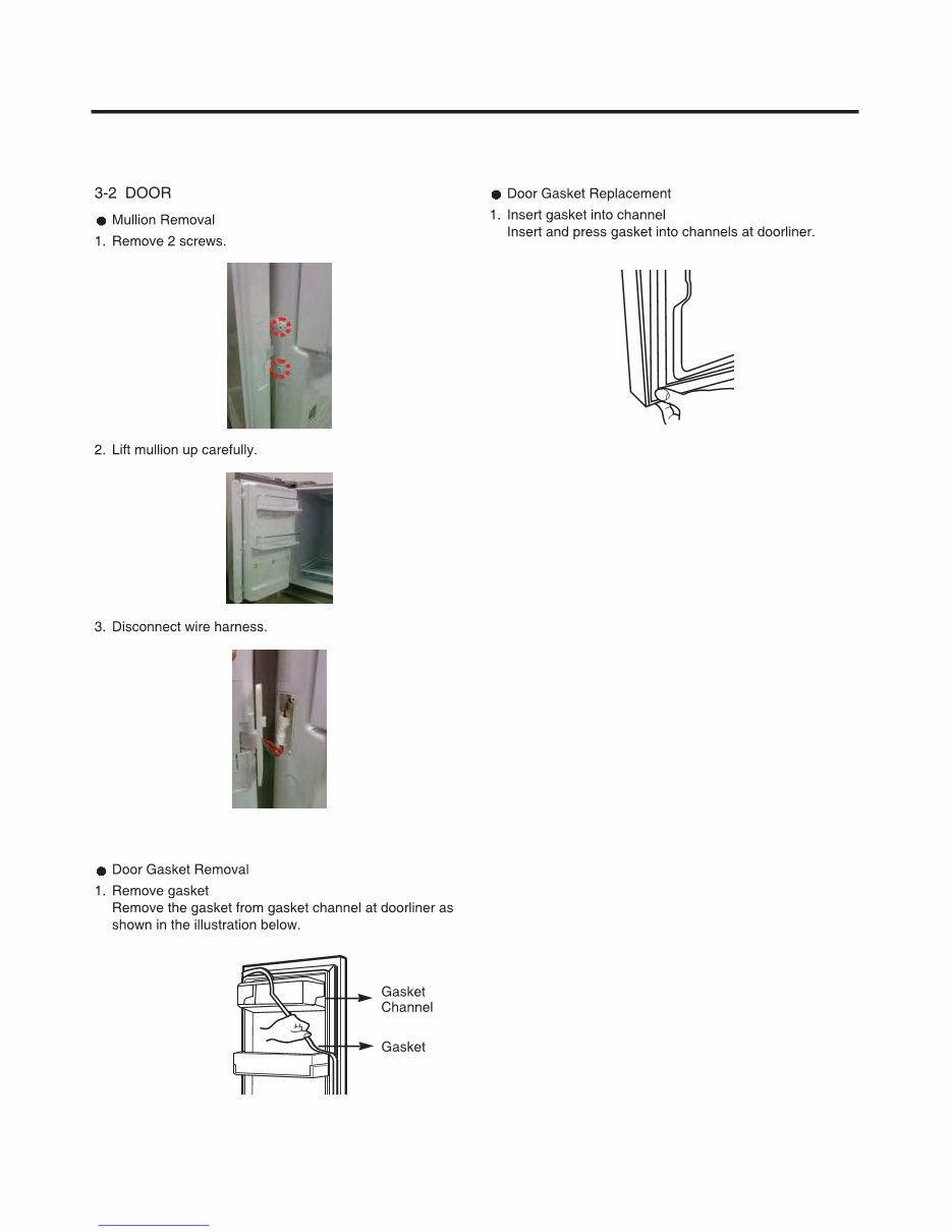
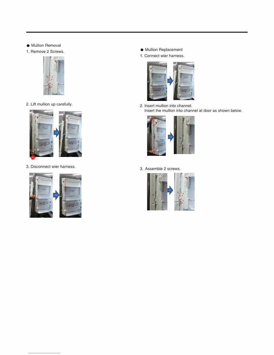
DOOR .............................................................................................................................................................................. 6-7
SUB, PCB ............................................................................................................................................................................8
DOOR ALIGNMENT ............................................................................................................................................................ 9
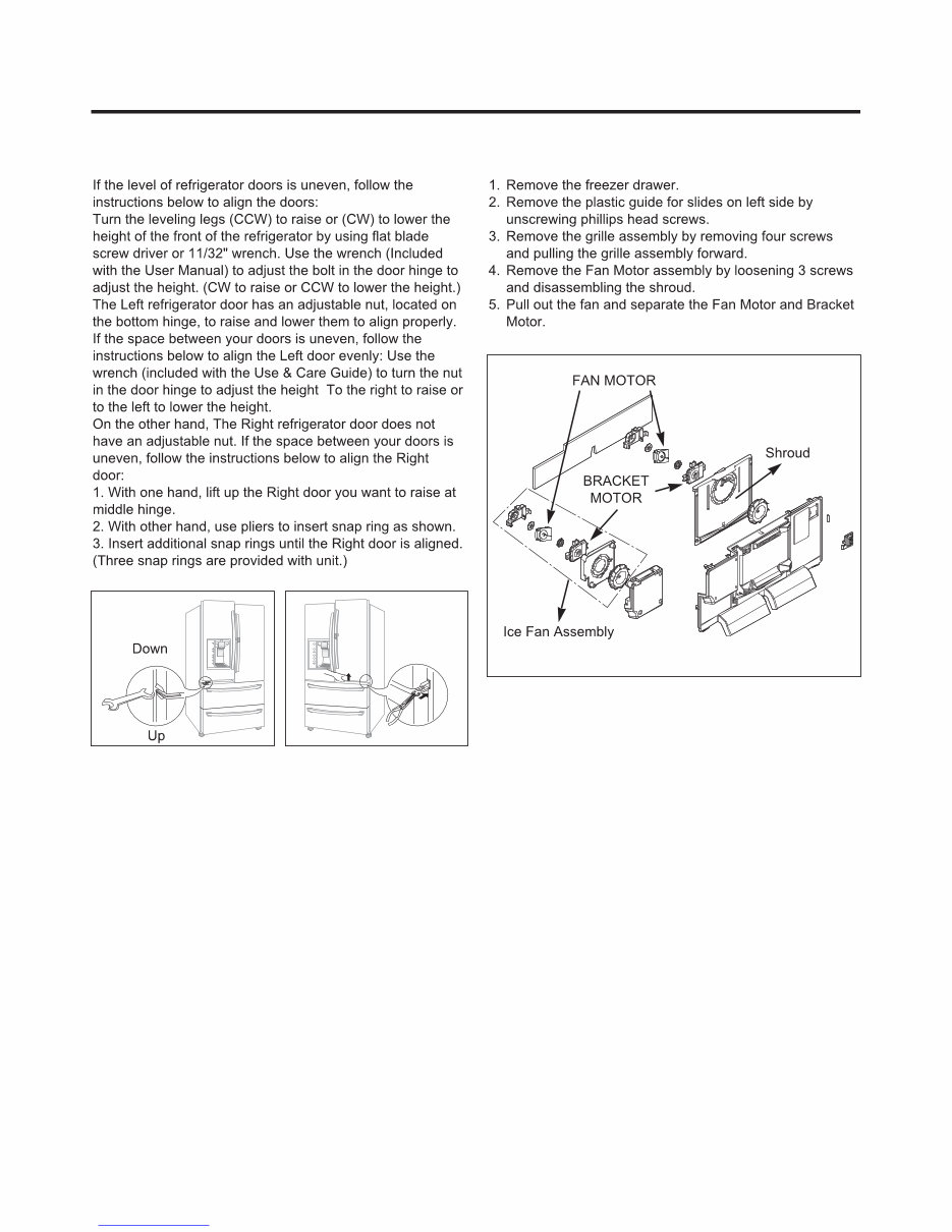
FAN AND FAN MOTOR................................................................................................................................................. 9-10
REFRIGERATOR LIGHT (TOP) ....................................................................................................................................11-12
MULTI DUCT ..................................................................................................................................................................... 12
DISPENSER ...................................................................................................................................................................... 13
DISPLAY PCB ................................................................................................................................................................... 13
CUSTOMCHILL DISPLAY ........................................................................................................................................... 13-14
ICE BUTTON ASSEMBLY ................................................................................................................................................. 14
WATER BUTTON ASSEMBLY .......................................................................................................................................... 14
ICE CORNER DOOR REPLACEMENT............................................................................................................................. 14
ICEMAKER REPLACEMENT ............................................................................................................................................ 15
SUB PCB FOR WORKING DISPENSER .......................................................................................................................... 15
CAP DUCT MOTOR REPLACEMENT .............................................................................................................................. 16
MODULE FILTER REPLACAEMENT ................................................................................................................................ 16
MODULE FILTER PART REPALCEMENT........................................................................................................................ 17
HOW TO REMOVE A ICE BIN .......................................................................................................................................... 17
HOW TO INSERT A ICE BIN............................................................................................................................................. 17
CUSTOMCHILL DRAWER ........................................................................................................................................... 18-21
HOT TO REMOVE AND REINSTALL THE PULLOUT DRAWER ................................................................................ 22-23
WATER VALVE DISASSEMBLY METHOD ...................................................................................................................... 24
FAN MOTOR DISASSEMBLY METHOD .......................................................................................................................... 24
CAUTION : SEALED SYSTEM REPAIR ........................................................................................................................... 25
WAY VALVE SERVICE ..................................................................................................................................................... 25
HOW TO REMOVE AND REINSTALL THE HOMEBAR .................................................................................................. 26
HOW TO REMOVE AND REINSTALL THEHOMEBAR DOOR ........................................................................................ 27
HOW TO REMOVE AND REINSTALL THE DOOR FOAM ASSEMBLY, REFRIGERATOR ............................................ 28
HOW TO REMOVE FRAME DOOR SWITCH OF DOOR FOAM ...................................................................................... 29
4. ADJUSTMENT ................................................................................................................................................................... 30
COMPRESSOR ................................................................................................................................................................. 30
5. CIRCUIT DIAGRAM ........................................................................................................................................................... 31
6. TROUBLESHOOTING .................................................................................................................................................. 32-33
7. PCB PICTURE .............................................................................................................................................................. 34-35
8. TROUBLESHOOTING WITH ERROR DISPLAY ......................................................................................................... 34-78
9. REFERENCE ................................................................................................................................................................ 79-82
10. COMPONENT TESTING INFORMATION .................................................................................................................. 83-92
11. COMPRESSOR TROUBLESHOOTING ................................................................................................................... 93-105
12. ICEMAKER OPERATIONG METHOD AND TROUBLE SHOOTING .................................................................... 106-109
13. DESCRIPTION OF FUNCTION & CIRCUIT OF MICOM ......................................................................................... 110-113
14. EXPLODED VIEW & REPLACEMENT PARTS LIST.................................................................................................... 114
Downloaded from www.Manualslib.com manuals search engine
- 3 -
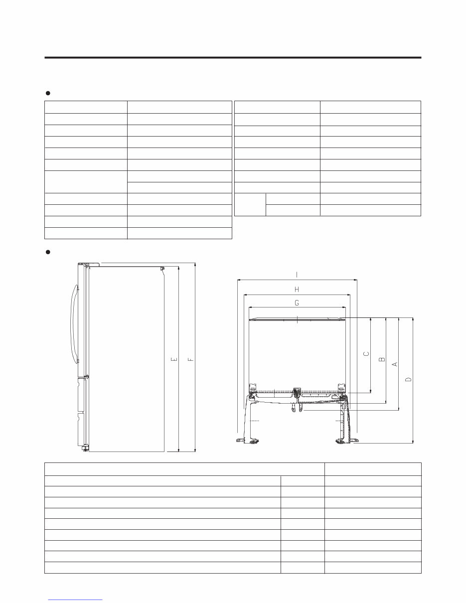
1. SPECIFICATIONS
1-1 LMXS30776S
DOOR DESIGN
DIMENSIONS (inches)
NET WEIGHT (pounds)
COOLING SYSTEM
TEMPERATURE CONTROL
DEFROSTING SYSTEM
DOOR FINISH
HANDLE TYPE
INNER CASE
INSULATION
ITEMS
Side Rounded
35
3
/4 X 38
1
/8 X 70
1
/4 (WXDXH) 30cu.ft.
180kg(397lb)
Fan Cooling
Micom Control
Full Automatic
Heater Defrost
Stainless
Bar
ABS Resin
Polyurethane Foam
SPECIFICATIONS
30 cu.ft.
VEGETABLE TRAY
COMPRESSOR
EVAPORATOR
CONDENSER
REFRIGERANT
LUBRICATING OIL
DEFROSTING DEVICE
ITEMS
Clear Drawer Type
Linear
Fin Tube Type
Spiral Condenser (AI)
R-134a(135g)
ISO10 (280 ml)
SHEATH HEATER
LED Module
LED Module
SPECIFICATIONS
LAMP
REFRIGERATOR
FREEZER
DIMENSIONS
Depth w/ Handles
Depth w/o Handles
Depth w/o Door
Depth (Total with Door Open)
Height to Top of Case
Height to Top of Door Hinge
Width
Width (door open 90 deg. w/o handle)
Width (door open 90 deg. w/ handle)
A
B
C
D
E
F
G
H
I
38 1/8 in
35 5/8 in
30 7/8 in
49 ½ in
68 3/4 in
70 1/4 in
35 3/4 in
40 in
45 in
Description LMXS30776S
Downloaded from www.Manualslib.com manuals search engine
- 4 -
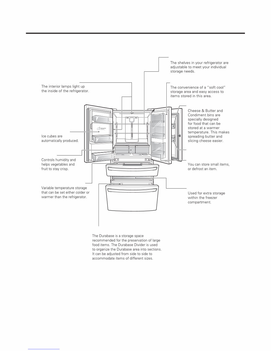
2. PARTS IDENTIFICATION
Door-In-Door Case
Adjustable Refrigerator Shelf
Cheese & Butter Bin
Condiment Bin
Pullout Drawer
EasyReach™
Indoor Ice Bin
Crisper
Custom Chill™ Drawer
Durabase® and Durabase® Divider
LED interior lamps
Downloaded from www.Manualslib.com manuals search engine
- 5 -
3. DISASSEMBLY
3-1 REMOVING AND REPLACING REFRIGERATOR DOORS
Downloaded from www.Manualslib.com manuals search engine
- 6 -
Downloaded from www.Manualslib.com manuals search engine
- 7 -
Downloaded from www.Manualslib.com manuals search engine
- 8 -
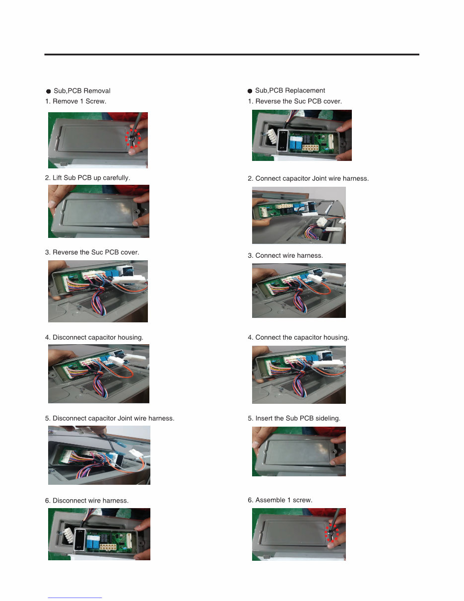
3-3 Sub, PCB
Downloaded from www.Manualslib.com manuals search engine
- 9 -
3-4 Door Alignment 3-5 FAN AND FAN MOTOR
Downloaded from www.Manualslib.com manuals search engine
- 10 -
Downloaded from www.Manualslib.com manuals search engine
You're Reading a Preview
What's Included?
Fast Download Speeds
Online & Offline Access
Access PDF Contents & Bookmarks
Full Search Facility
Print one or all pages of your manual
$36.99
Viewed 31 Times Today


Secure transaction
What's Included?
Fast Download Speeds
Online & Offline Access
Access PDF Contents & Bookmarks
Full Search Facility
Print one or all pages of your manual
$36.99
This official service and repair manual for the LG LMXS30776S French Door Refrigerator is an essential resource for both professional technicians and DIY enthusiasts. It provides comprehensive guidance on troubleshooting and repairing the refrigerator, covering the following key areas:
- Product Specifications
- Parts Identification
- Disassembly Instructions
- Troubleshooting
- Adjustment Procedures
- Operation Principle and Repair Method of the Ice-maker
- Circuit Diagram
- Description of Functions & Circuits
- Printed Circuit Board
- Error Codes
- Exploded Views
This detailed manual is accompanied by illustrations and step-by-step instructions, ensuring the best possible guidance for servicing and repairing the refrigerator. It is available in a high-resolution format, guaranteeing excellent print quality when needed. The manual can be easily printed from any computer and printer, providing instant access without any shipping delays. The language of the manual is English, and it consists of 122 pages.


