

LG LFXS30726S LFXS30726W LFXS30726B Service Manual & Repair Guide
What's Included?
Fast Download Speeds
Online & Offline Access
Access PDF Contents & Bookmarks
Full Search Facility
Print one or all pages of your manual
CAUTION
BEFORE SERVICING THE UNIT,
READ THE SAFETY PRECAUTIONS IN THIS MANUAL.
MODEL : LFXS30726*
COLOR : STAINLESS(ST)
REFRIGERATOR
SERVICE MANUAL

- 2 -
CONTENTS
SAFETY PRECAUTIONS ....................................................................................................................................................... 2
1. SPECIFICATIONS ............................................................................................................................................................. 3
2. PARTS IDENTIFICATION ................................................................................................................................................. 4
3. DISASSEMBLY ............................................................................................................................................................ 5-18
REMOVING AND REPLACING REFRIGERATOR DOORS .......................................................................... 5
DOOR .............................................................................................................................................................. 6
SUB PCB FOR WORKING DISPENSER .........................................................................................................7
DOOR ALIGNMENT ....................................................................................................................................... 8
FAN AND FAN MOTOR................................................................................................................................... 8
DEFROST CONTROL ASSEMBLY ................................................................................................................ 8
REFRIGERATOR LIGHT (TOP) ................................................................................................................ 9-10
MULTI DUCT ................................................................................................................................................ 10
DISPENSER ................................................................................................................................................. 11
DISPLAY PCB .............................................................................................................................................. 11
ICE BUTTON ASSEMBLY ............................................................................................................................ 11
WATER BUTTON ASSMEBLY ..................................................................................................................... 11
ICE CORNER DOOR REPLACEMENT ........................................................................................................ 11
ICEMAKER REPLACEMENT ....................................................................................................................... 12
CAP DUCT MOTOR REPLACEMENT ......................................................................................................... 12
HOW TO REMOVE A ICE BIN ..................................................................................................................... 13
HOW TO PLACE ICE BIN IN POSITION........................................................................................................13
HOW TO REMOVE AND REINSTALL THE PULLOUT DRAWER ......................................................... 14-15
WATER VALVE DISASSEMBLY METHOD .................................................................................................................... 16
FAN AND FAN MOTOR DISASSEMBLY METHOD......................................................................................................... 16
PULL OUT DRAWER ...................................................................................................................................................... 17
CAUTION : SEALED SYSTEM REPAIR ......................................................................................................................... 18
3WAY VALVE SERVICE ...................................................................................................................................................18
4. ADJUSTMENT ................................................................................................................................................................ 19
COMPRESSOR ................................................................................................................................................................ 19
5. CIRCUIT DIAGRAM ........................................................................................................................................................ 20
6. TROUBLESHOOTING ............................................................................................................................................... 21-22
7. PCB PICTURE ........................................................................................................................................................... 23-24
8. Trouble Shooting ...................................................................................................................................................... 25-64
9. Reference .................................................................................................................................................................. 65-67
10. COMPONENT TESTING INFORMATION .................................................................................................................. 68-80
11. COMPRESSOR TROUBLESHOOTING ................................................................................................................... 81-95
12. ICEMAKER OPEARTING METHOD AND TROUBLE SHOOTING .......................................................................... 96-97
13. DESCRIPTION OF FUNCTION & CIRCUIT OF MICOM ......................................................................................... 98-101
14.EXPLODE VIEW & REPLACEMENT PARTS LIST ........................................................................................................102
SAFETY PRECAUTIONS
Please read the following instructions before servicing your refrigerator.
1. Unplug the power before handling any elctrical componets.
2. Check the rated current, voltage, and capacity.
3. Take caution not to get water near any electrical components.
4. Use exact replacement parts.
5. Remove any objects from the top prior to tilting the product.
- 3 -
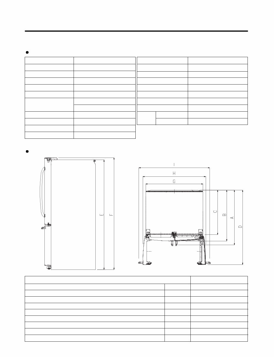
1. SPECIFICATIONS
1-1 LFXS30726*
DOOR DESIGN
DIMENSIONS (inches)
NET WEIGHT (pounds)
COOLING SYSTEM
TEMPERATURE CONTROL
DEFROSTING SYSTEM
DOOR FINISH
HANDLE TYPE
INNER CASE
INSULATION
ITEMS
Side Rounded
35
3
/4 X 36
1
/4X 70
1
/4 (WXDXH) 29.8cu.ft.
150kg (331lb)
Fan Cooling
Micom Control
Full Automatic
Heater Defrost
PCM, VCM, Stainless
Bar
ABS Resin
Polyurethane Foam
SPECIFICATIONS
29.8 cu.ft.
VEGETABLE TRAY
COMPRESSOR
EVAPORATOR
CONDENSER
REFRIGERANT
LUBRICATING OIL
DEFROSTING DEVICE
ITEMS
Clear Drawer Type
Linear
Fin Tube Type
Spiral Condenser
R-134a (135 g)
ISO10 (280 ml)
SHEATH HEATER
LED Module
LED Module
SPECIFICATIONS
LAMP
REFRIGERATOR
FREEZER
DIMENSIONS
Depth w/ Handles
Depth w/o Handles
Depth w/o Door
Depth (Total with Door Open)
Height to Top of Case
Height to Top of Door Hinge
Width
Width (door open 90 deg. w/o handle)
Width (door open 90 deg. w/ handle)
A
B
C
D
E
F
G
H
I
36 1/4 in
33 3/4 in
29 1/2 in
48 1/8 in
68 7/8 in
70 1/4 in
35 3/4 in
40 in
44 1/4 in
Description LFXS30726*
- 4 -
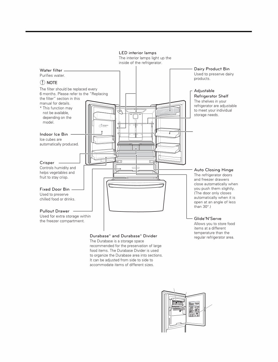
2. PARTS IDENTIFICATION
Modular Door Bin
Interchangeable bins can
be arranged to suit your
storage needs.
Ice Bin
Icemaker
Ice Compartment Door
- 5 -
3. DISASSEMBLY
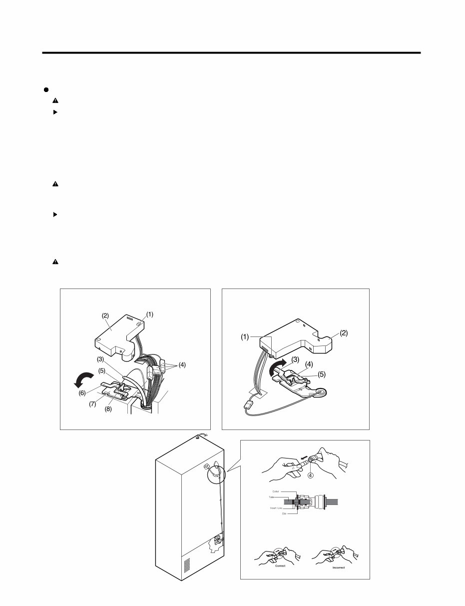
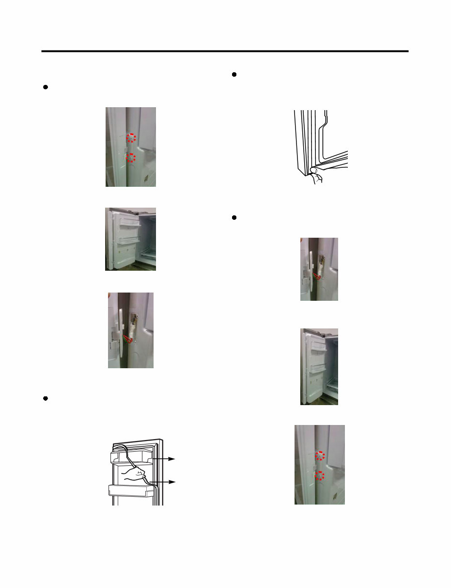
3-1 REMOVING AND REPLACING REFRIGERATOR DOORS
Removing Refrigerator Door
CAUTION: Before you begin, unplug the refrigerator. Remove food and bins from doors.
Left Door -FIG. 2
1. Disconnect water supply tube by pushing back on the disconnect ring (3).-FIG. 1
2. Open door. Loosen top hinge cover screw (1).
Use flat tip screwdriver to pry back hooks on front underside of cover (2). Lift up cover.
3. Disconnect door switch wire harness and remove the cover.
4. Pull out the tube.
5. Disconnect all 3 wiring harnesses (4). Remove the grounding screw (5).
6. Rotate hinge lever (6) counterclockwise. Lift top hinge (7) free of hinge lever latch (8).
7. Lift door from middle hinge pin and remove door.
8. Place the door with the insides facing up, on a not scratch surface.
CAUTION: When lifting hinge free from the latch, be careful that door does not fall forward.
Right Door -FIG. 3
1. Open the door, remove 1 screw on the top of the hinge cover. Loosen top hinge cover screw (1). Lift up cover (2).
2. Disconnect door switch wire harness and remove the cover.
3. Rotate hinge lever (3) clockwise. Lift top hinge (4) free of hinge lever latch (5).
4. Lift door from middle hinge pin and remove door.
5. Place the door with the insides facing up, on a not scratch surface.
CAUTION: When lifting hinge free from the latch, be careful that the door does not fall forward.
Figure 2 Figure 3
Figure 1
1) Insert the tube until you can see only one of
the lines printed on the tube.
2) After inserting, pull the tube to ascertain that
it is secure.
3) Assemble clip.
- 6 -
1. Remove gasket
Remove the gasket from gasket channel at doorliner as
shown in the illustration below.
3-2 DOOR
Mullion Removal
1. Remove 2 screws.
Door Gasket Removal
2. Lift mullion up carefully.
3. Disconnect wire harness.
Door Gasket Replacement
1. Insert gasket into channel
Insert and press gasket into channels at doorliner.
2. Insert mullion into channel.
Insert the mullion into channel at door as shown below.
Mullion Replacement
1. Connect wire harness.
3. Assemble 2 screws.
Gasket
Gasket
Channel
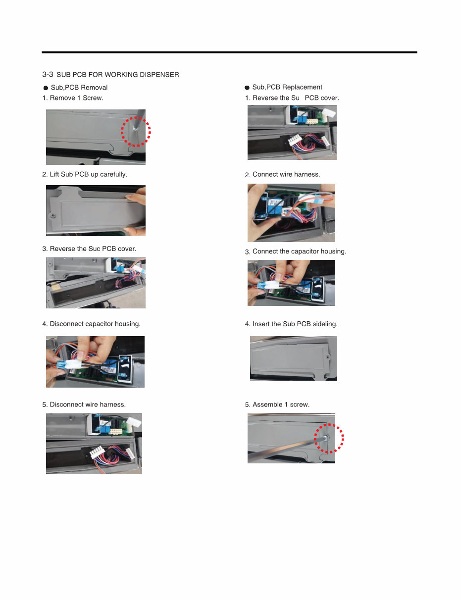
- 7 -
b
- 8 -
(1) (2)
(3) (4)
(5) (6)
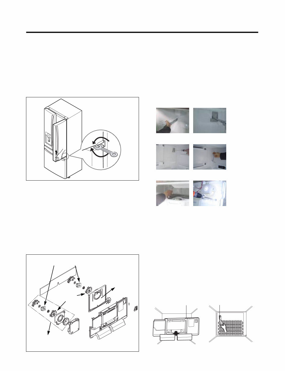
GRILLE ASSEMBLY
DEFROST-CONTROL
ASSEMBLY
FAN MOTOR
BRACKET
MOTOR
Shroud
Up
Down
Ice Fan Assembly
* Ice Fan Assembly Replacement
1) Remove the plastic guide for slides on left side by
unscrewing phillips head screws.
2) Pull out the cover sensor to disassemble by using tools
shown in the figure.
3) Pull out the cover grille to disassemble by using tools
shown in the figure.
4) Put your hand into the inside of grille to disassemble
shown in the figure.
5) Disconnect wire harness of the grille assembly.
6) Remove the Ice fan assembly by loosening all screws.
3-6 DEFROST CONTROL ASSEMBLY
Defrost Control assembly consists of Defrost Sensor and
FUSE-M.
The Defrost Sensor works to defrost automatically. It is
attached to the metal side of the Evaporator and senses its
temperature. At 46F(8°C), it turns the Defrost Heater off.
Fuse-M is a safety device for preventing over-heating of
the Heater when defrosting.
1. Pull out the grille assembly. (Figure 1)
2. Separate the connector with the Defrost Control
assembly and replace the Defrost Control assembly after
cutting the Tie Wrap. (Figure 2)
3-4 Door Alignment
If the level of refrigerator doors is uneven, follow the
instructions below to align the doors:
Turn the leveling legs (CW) to raise or (CCW) to lower the
height of the front of the refrigerator by using flat blade
screw driver or 11/32" wrench. Use the wrench (Included
with the Owners Manual) to adjust the bolt in the door hinge
to adjust the height. (CW to raise or CCW to lower the
height.)
3-5 FAN AND FAN MOTOR
1. Remove the freezer drawer.
2. Remove the plastic guide for slides on left side by
unscrewing phillips head screws.
3. Remove the grille assembly by removing four screws
and pulling the grille assembly forward.
4. Remove the Fan Motor assembly by loosening 3 screws
and disassembling the shroud.
5. Pull out the fan and separate the Fan Motor and Bracket
Motor.
- 9 -
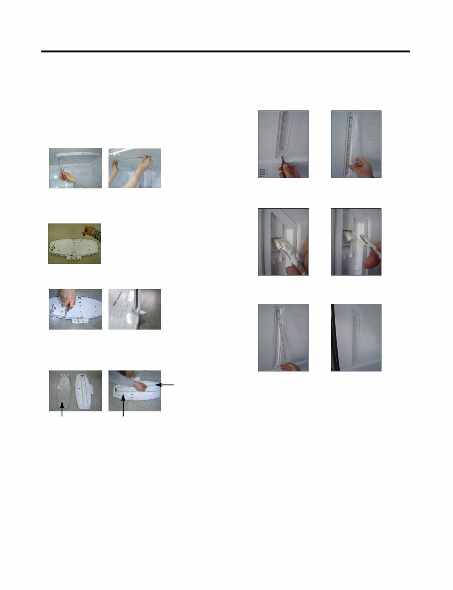
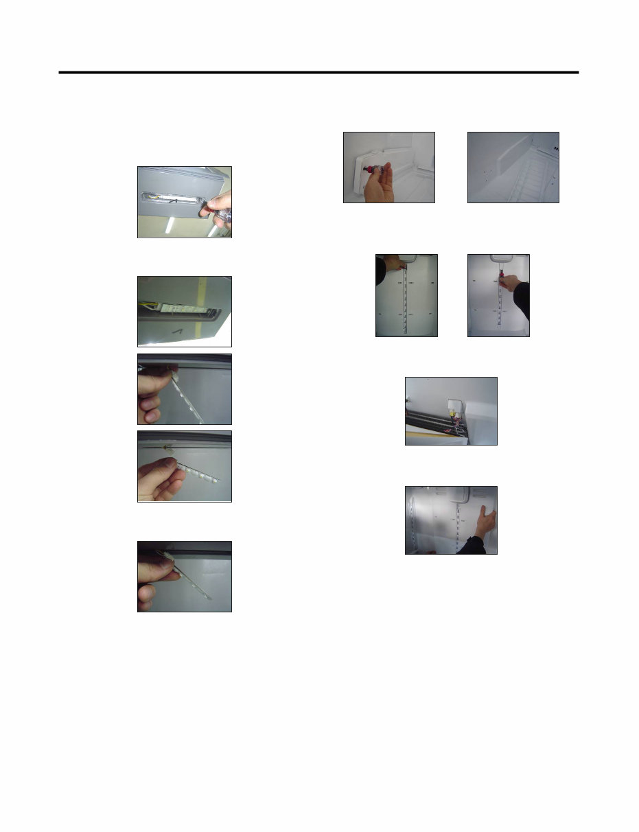
3-7 Refrigerator Light (Top)
Unplug Refrigerator, or disconnect power at the circuit
breaker.
If necessary, remove top shelf or shelves.
1) Release 2 screws.
2) Hold both ends with your both hands and pull it
downward to remove it.
3-7-1 Refrigerator Compartment Lamp
4) Use a flat blade screwdriver as shown below to remove
the cover lamp.
5) To remove the LED Assembly, open the Hook part to pull
it out as shown in the following picture.
Cover, lamp
Case, lamp
LED, Assembly
3) To remove the case lamp and cover lamp, release
another 2 screws as following picture.
3-7-2 Refrigerator Light (Side)
1. Unplug refrigerator power cord from electric outlet.
2. Put flat screwdriver into sevice hole and remove cover of
refrigerator light.
3. Remove the LED assembly from connector.
4. Replace LED assembly.
5. Assemble the cover in reverse order.
- 10 -
3-8 MULTI DUCT 3-7-3 Cap Decor LED LAMP(Bottom)
1. Unplug refrigerator power cord from electric outlet.
2. Open the refrigerator door to need diassembly.
3. Put flat screwdriver into service hole, remove the cover
of cap decor LED LAMP.
5. Replace LED assembly.
6. Assembly the cover in reverse order.
4. Remove the LED assembly from connector.
1. Remove 2 screws and guide rail.
2. Remove the upper and lower Caps by using a flat
screwdriver and remove 2 screws as shown figure.
3. Disconnect the lead wire on the bottom position
4. Grip both side of multi duct, pull it out.
You're Reading a Preview
What's Included?
Fast Download Speeds
Online & Offline Access
Access PDF Contents & Bookmarks
Full Search Facility
Print one or all pages of your manual
$36.99
Viewed 37 Times Today


Secure transaction
What's Included?
Fast Download Speeds
Online & Offline Access
Access PDF Contents & Bookmarks
Full Search Facility
Print one or all pages of your manual
$36.99
This official service and repair manual for the LG LFXS30726S, LFXS30726W, LFXS30726B French Door Refrigerator is an essential resource for both professional technicians and DIY enthusiasts. It provides comprehensive guidance on troubleshooting and repairing the fridge, covering the following areas:
- Product Specifications
- Parts Identification
- Disassemble Instructions
- Troubleshooting
- Adjustment Procedures
- Operation Principle and Repair Method of the Ice-maker
- Schematic Circuit Diagram
- Description of Functions & Circuits
- Printed Circuit Board
- Error Codes
- Exploded Views
This detailed manual is illustrated with pictures and step-by-step instructions, ensuring the best approach to servicing and repairing the device. It is available in high resolution, guaranteeing excellent print quality when needed. The manual is accessible instantly after purchase, eliminating shipping delays and allowing for immediate access to the valuable information it contains.
Specifications:
- Language: English
- Format: PDF
- Pages: 109


