REFRIGERATOR SERVICE MANUAL CAUTION BEFORE SERVICING THE UNIT, READ THE SAFETY PRECAUTIONS IN THIS MANUAL. MODEL : LFX25974** COLOR : STAINLESS(ST) WESTERN BLACK SUPER WHITE Downloaded from www.Manualslib.com manuals search engine
CONTENTS - 2 - 1. SPECIFICATIONS .............................................................................................................................................................. 3 2. PARTS IDENTIFICATION .................................................................................................................................................. 4 3. DISASSEMBLY ............................................................................................................................................................. 5-17 REMOVING AND REPLACING REFRIGERATOR DOORS ............................................................................................... 5 DOOR .................................................................................................................................................................................. 6 DOOR ALIGNMENT ........................................................................................................................................................... 7 FAN AND FAN MOTOR(EVAPORATOR) .......................................................................................................................... 7 DEFROST CONTROL ASSEMBLY .................................................................................................................................... 7 LAMP .................................................................................................................................................................................. 8 MULTI DUCT ...................................................................................................................................................................... 8 MAIN PWB ........................................................................................................................................................................... 8 DISPENSER ....................................................................................................................................................................... 9 DISPLAY PCB ..................................................................................................................................................................... 9 ICE BUTTON ASSEMBLY .................................................................................................................................................. 9 WATER BUTTON ASSMEBLY ........................................................................................................................ 9 ICE COMPARTMENT DOOR REPLACEMENT .............................................................................................. 9 ICEMAKER REPLACEMENT ........................................................................................................................ 10 SUB PWB FOR WORKING DISPENSER ..................................................................................................... 10 CAP DUCT MOTOR REPLACEMENT .......................................................................................................... 11 HOW TO REMOVE THE ICE BIN ................................................................................................................. 12 HOW TO INSERT THE ICE BIN .................................................................................................................... 12 HOW TO REMOVE AND REINSTALL THE PULLOUT DRAWER ................................................................ 13 WATER VALVE DISASSEMBLY METHOD .................................................................................................. 15 BOTTOM DRAWER ....................................................................................................................................... 16 4. ADJUSTMENT .................................................................................................................................................................. 17 COMPRESSOR ................................................................................................................................................................ 17 5. CIRCUIT DIAGRAM ......................................................................................................................................................... 18 6. TROUBLESHOOTING ...................................................................................................................................................... 19 ERROR CODE SUMMARY .............................................................................................................................................. 19 7. PCB PICTURE ............................................................................................................................................................. 20-21 MAIN PCB ......................................................................................................................................................................... 20 DISPLAY PCB & SUB PCB .......................................................................................................................... 21 8. TROUBLESHOOTING WITH ERROR DISPLAY .................................................................................... 22-30 9. TROUBLESHOOTING WITH ERROR DISPLAY ........................................................................................................ 31-39 10. REFERENCE ............................................................................................................................................................. 40-43 11. COMPONENT TESTING INFORMATION ................................................................................................................ 44-52 12. COMPRESSOR TROUBLESHOOTING ................................................................................................................... 53-64 13. OPERATION PRINCIPLE AND REPAIR METHOD OF ICEMAKER ....................................................................... 65-66 ICEMAKER’S BASIC OPERATING METHOD ............................................................................................................... 65 ICE MAKER FUNCTIONS .............................................................................................................................................. 66 TROUBLE SHOOTING ICE & WATER SYSTEM ISSUES ............................................................................................ 66 14. DESCRIPTION OF FUNCTION & CIRCUIT OF MICOM ............................................................................................... 69 FUNCTION ................................................................................................................................................................ 69-72 15. EXPLODED VIEW ......................................................................................................................................................... 1-7 SAFETY PRECAUTIONS Please read the following instructions before servicing your refrigerator. 1. Unplug the power before handling any elctrical componets. 2. Check the rated current, voltage, and capacity. 3. Take caution not to get water near any electrical components. 4. Use exact replacement parts. 5. Remove any objects from the top prior to tilting the product. Downloaded from www.Manualslib.com manuals search engine
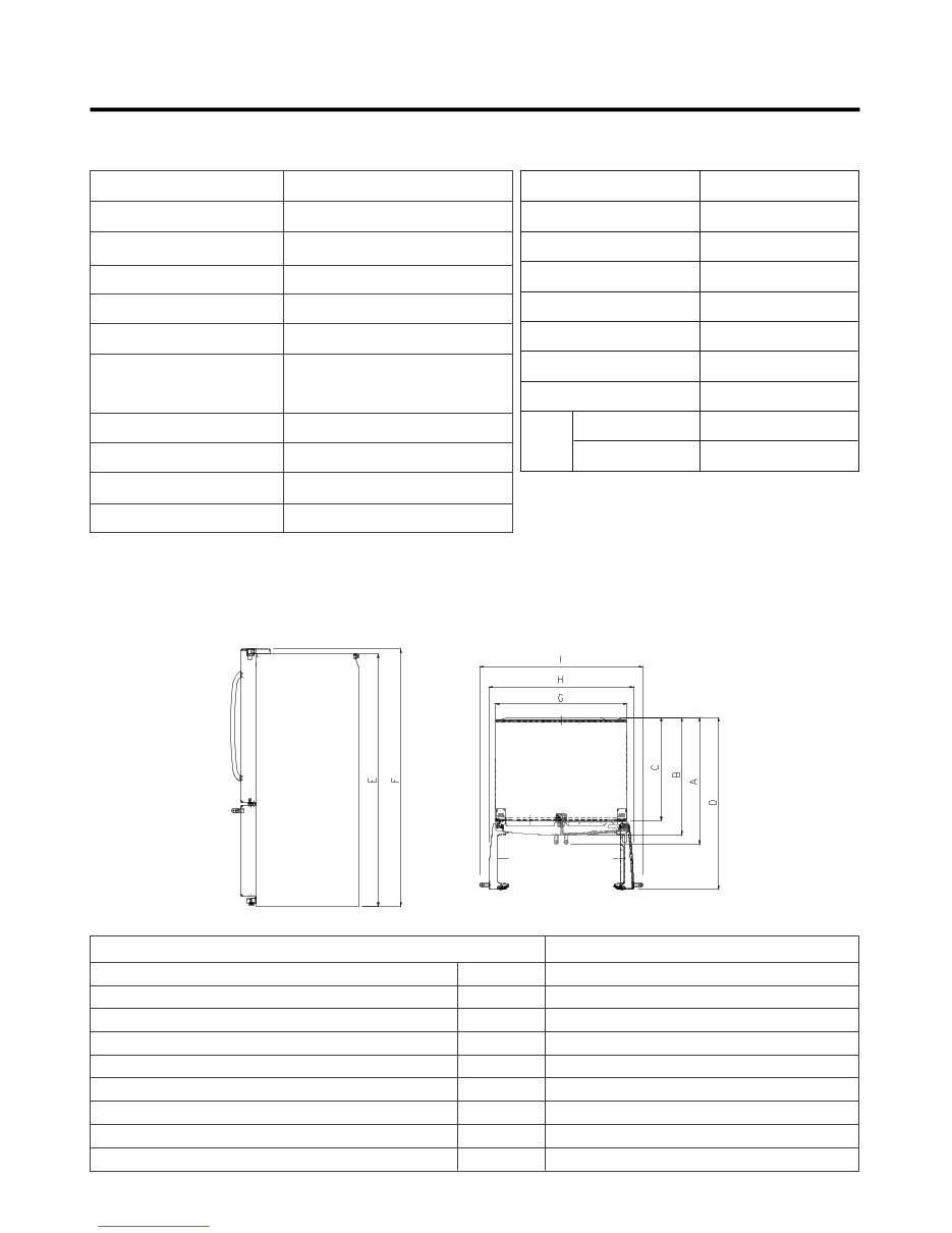
1. SPECIFICATIONS - 3 - Opaque Drawer Type Linear Fin Tube Type Wire Condenser R-134a (150g) FREOLα 8G (180 ml) SHEATH HEATER LED Module(21) Bulb Lamp VEGETABLE TRAY COMPRESSOR EVAPORATOR CONDENSER REFRIGERANT LUBRICATING OIL DEFROSTING DEVICE REFRIGERATOR FREEZER LAMP ITEMS SPECIFICATIONS Side Rounded 35 3/ 4 X 34 1/ 4 X 69 3/ 4 (WXDXH) 25cu.ft 308.65 (25cu.ft) Fan Cooling Micom Control Full Automatic Heater Defrost PCM, Stainless Bar ABS Resin Polyurethane Foam DOOR DESIGN DIMENSIONS (inches) NET WEIGHT (pounds) COOLING SYSTEM TEMPERATURE CONTROL DEFROSTING SYSTEM DOOR FINISH HANDLE TYPE INNER CASE INSULATION ITEMS SPECIFICATIONS Description LMX25986** Depth w/ Handles Depth w/o Handles Depth w/o Door Depth (Total with Door Open) Height to Top of Case Height to Top of Door Hinge Width Width (door open 90 deg. w/o handle) Width (door open 90 deg. w/ handle) A B C D E F G H I 34 1/4 in. 31 3/4 in. 27 7/8 in. 46 1/2 in. 68 3/8 in. 69 3/4 in. 35 3/4 in. 39 1/4 in. 44 1/4 in. DIMENSIONS 25 cu. ft Downloaded from www.Manualslib.com manuals search engine
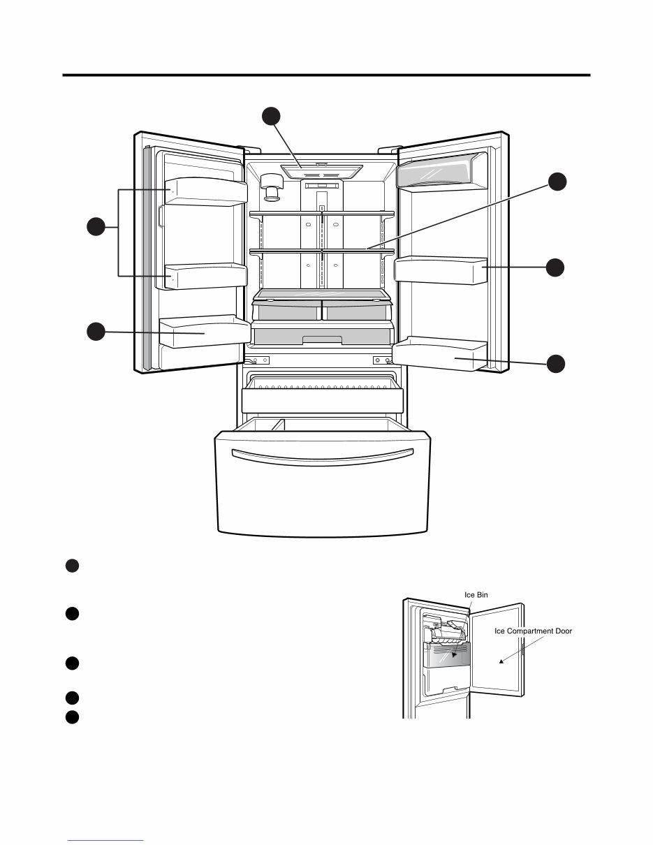
2. PARTS IDENTIFICATION - 4 - 3 5 4 1 5 2 ADJUSTABLE REFRIGERATOR SHELVING The refrigerator compartment shelves are adjustable to allow flexibility for storage needs. 1 GALLON STORAGE BINS Two interchangeable bins can be arranged to suit your storage needs. 2 LED INTERIOR LAMPS Refrigerator interior is lit by the LED array. 3 CAN STORAGE BIN 4 FIXED DOOR BINS 5 Downloaded from www.Manualslib.com manuals search engine
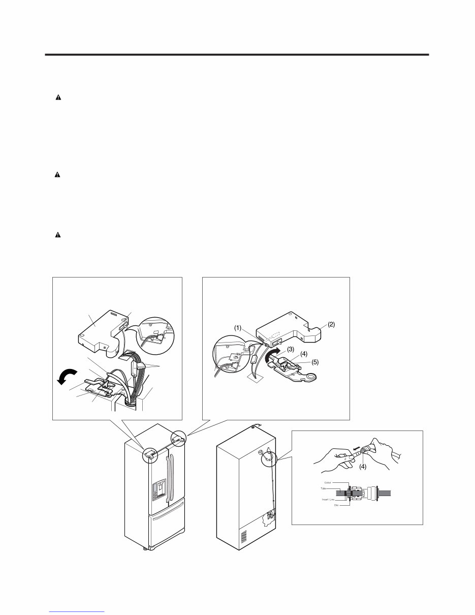
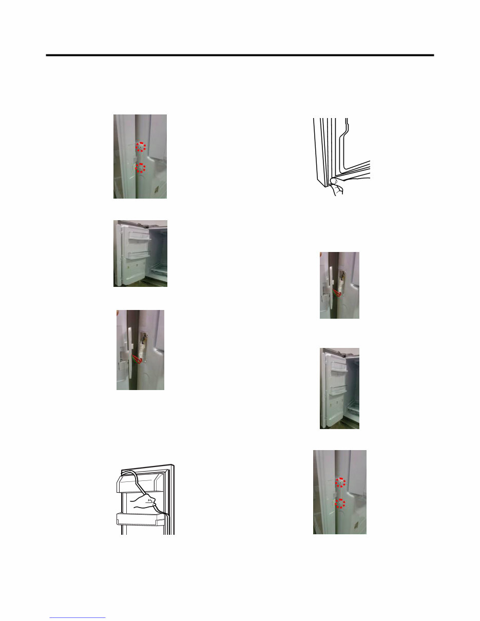
● Removing Refrigerator Door CAUTION : Before you begin, unplug the refrigerator. Remove food and bins from doors. ▶Left Door -FIG. 2 1. Disconnect water supply tube by pushing back on the disconnect ring (4).-FIG. 1 2. Open door. Loosen top hinge cover screw (1). Use flat tip screwdriver to pry back hooks on front underside of cover (2). Lift up cover. 3. Disconnect door switch wire harness. Remove cover. 4. Pull out the tube(3). 5. Disconnect the two wire harnesses (4). Remove the grounding screw (5). 6. Rotate hinge lever (6) counterclockwise. Lift top hinge (7) free of hinge lever latch (8). CAUTION : When lifting hinge free of latch, be careful that door does not fall forward. 7. Place door, inside facing up, down onto a non-scratching surface. ▶Right Door -FIG. 3 1. Open door. Loosen top hinge cover screw (1). Lift up cover (2). 2. Disconnect door switch wire harness. Remove cover. 3. Rotate hinge lever (3) clockwise. Lift top hinge (4) free of hinge lever latch (5). 4. Lift door from middle hinge pin and remove door. CAUTION : When lifting hinge free of latch, be careful that door does not fall forward. 5. Place door, inside facing up, down onto a non-scratching surface. 3. DISASSEMBLY - 5 - 3-1 REMOVING AND REPLACING REFRIGERATOR DOORS (1) (2) (4) (3) (6) (7) (8) (5) Figure 1 Figure 2 Figure 3 Downloaded from www.Manualslib.com manuals search engine
- 6 - 1. Remove gasket Pull gasket free from gasket channel on the four remaining sides of door. 3-2 DOOR ● Pillar Removal 1. Remove 2 screws. ● Door Gasket Removal 2. Lift pillar up carefully. 3. Disconnect wire harness. ● Door Gasket Replacement 1. Insert gasket into channel Press gasket into channels on the four remaining sides of door. 2. Insert pillar into channel. Inserting pillar assy’ into bracket, door ● Pillar Replacement 1. Connect wire harness. 3. Assemble 2 screws. Downloaded from www.Manualslib.com manuals search engine
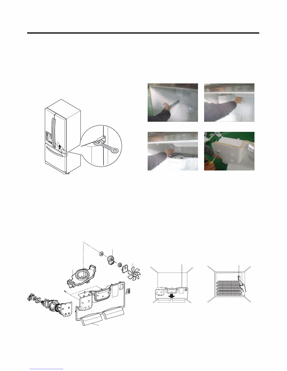
- 7 - 3-3 DOOR ALIGNMENT If the space between your doors is uneven, follow the instructions below to align the doors: Remove the Base Grillie. Turn the leveling legs (CCW) to raise or (CW) to lower the height of the front of the refrigerator by using flat blade screw driver or 11/32" wrench. Use the wrench (Included with the User Manual) to adjust the bolt in the door hinge to adjust the height. (CCW to raise or CW to lower the height.) 3-4 FAN AND FAN MOTOR(EVAPORATOR) 1. Remove the freezer shelf. 2. Remove the plastic guide for slides on left side by unscrewing phillips head screws. 3. Remove the grille by removing one screw and pulling the grille forward. 4. Remove the Fan Motor assembly by loosening 2 screws and disassembling the shroud. 5. Pull out the fan and separate the Fan Motor and Bracket. BRACKET MOTOR Ice fan assembly GRILLE FAN FAN MOTOR * Ice Fan Scroll Assembly Replacement 1) Remove the plastic guide for slides on left side by unscrewing phillips head screws. 2) Pull the grille forward as shown in the second picture. 3) Disconnect wire harness of the grille. 4) Remove the scroll assembly by loosening all screws. (3) (4) 3-5 DEFROST CONTROL ASSEMBLY Defrost Control assembly consists of Defrost Sensor and FUSE-M. The Defrost Sensor works to defrost automatically. It is attached to the metal side of the Evaporator and senses its temperature. At 46°F (8°C), it turns the Defrost Heater off. Fuse-M is a safety device for preventing over-heating of the Heater when defrosting. 1. Pull out the grille assembly. (Figure 4) 2. Separate the connector with the Defrost Control assembly and replace the Defrost Control assembly after cutting the Tie Wrap. (Figure 5) Figure 4 Figure 5 GRILLE ASSEMBLY DEFROST-CONTROL ASSEMBLY (1) (2) Downloaded from www.Manualslib.com manuals search engine
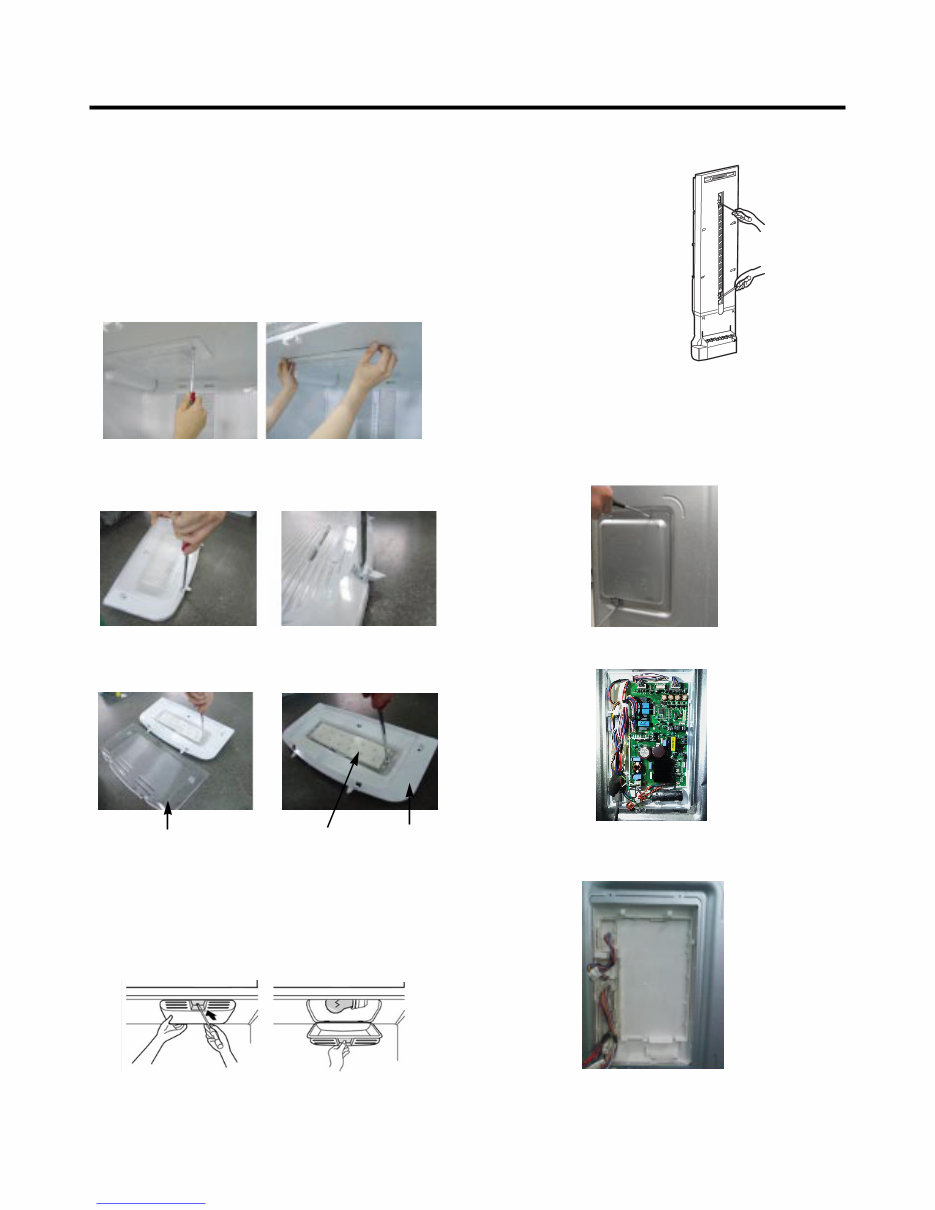
- 8 - Cover, Lamp LED, Assembly Case Lamp 3-6 LAMP Unplug Refrigerator, or disconnect power at the circuit breaker. If necessary, remove top shelf or shelves. 1) Release 2 screws. 2) Hold both ends with your both hands and pull it downward to remove it. 3) Use a flat tool as shown below to remove the cover lamp. 3-6-1 Refrigerator Compartment Lamp 1. Unplug refrigerator power cord from outlet. 2. Remove screw with driver. 3. Grasp the cover Lamp, pull the cover downward. 3-6-2 Freezer Compartment Lamp 4) As shown below, use a flat tool to remove the cover lamp. 3-7 MULTI DUCT 1. Remove the upper and lower Caps by using a flat screwdriver, and remove 2 screws. (Figure 6) 2. Disconnect the lead wire on the bottom position. 3-8 MAIN PWB 1) Loosen 3 screws on the PWB cover. Figure 6 2) Remove the PWB cover 3) Disconnect wire harness and replace the main PWB in the reverse order of removal. Downloaded from www.Manualslib.com manuals search engine
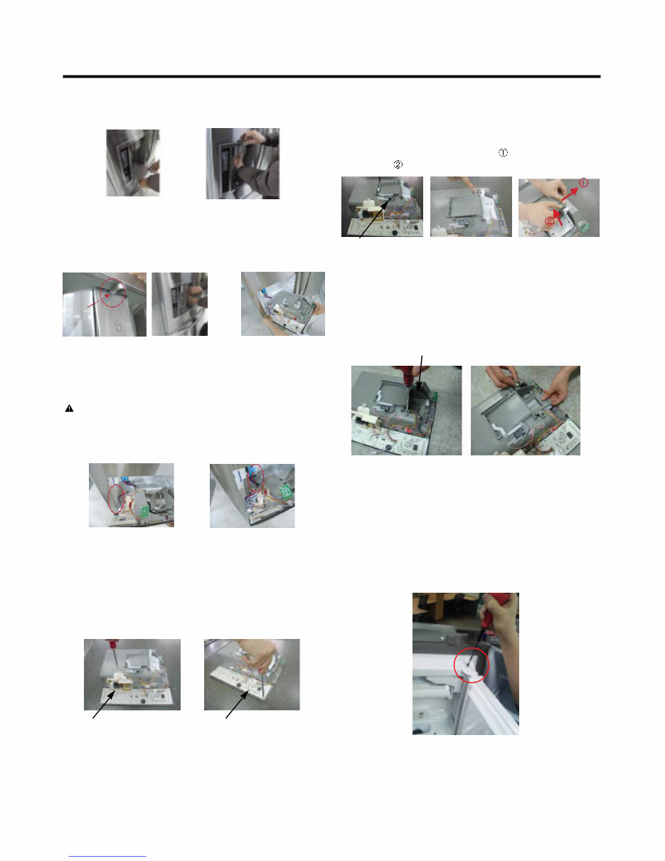
- 9 - 3-9 DISPENSER 1) Pull out the drain 2) Hold the inner side of cover dispenser with both hands at the handle side to pull it out forward. 3) If nozzle is interfered with button, push and pull out the bottom of button. 4) Remove the connected part of Lead wire. 3-10 DISPLAY PCB As shown below, remove 1 case PCB fixing screw. Remove the display PCB fixing screw. CAUTION: When replacing the dispensor cover in the reverse order of removal, be careful that the lead wire does not come out and the water tube is not pinched by the dispensor. Case, PCB Display PCB 3-11 ICE BUTTON ASSEMBLY 1) Remove the screw fixing the button lever. 2) Push the spring from the hanging hook to remove it. 3) Apply some pressure to the rib in direction and lift the button in direction. Button Lever 3-13 ICE COMPARTMENT DOOR REPLACEMENT 1) Loosen the front screw as shown in the picture. 2) Lift up the hinge with one hand. 3) Pull out the Ice Compartment Door with the other hand. 3-12 WATER BUTTON ASSMEBLY 1) Remove screws. 2) Grasp the Button assembly and lift up. Button Lever hinge Downloaded from www.Manualslib.com manuals search engine
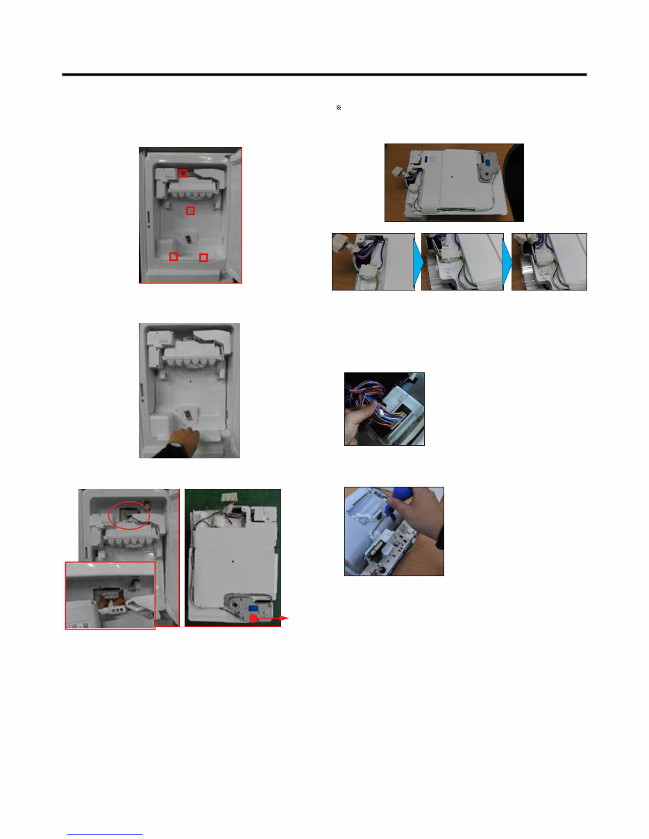
- 10 - 3-14 ICEMAKER REPLACEMENT 1) Remove the stainless screws marked in the picture below. 2) Grasp the bottom of motor cover assembly and pull it out slowly. 3) Disconnect wire harness from wall of compartment. In-door motor Caution: Check to see if the housing is stuck to mold and taped. If the housing is not on its original position, it will disturb Cover, motor to be positioned to the unit. 3-15 SUB PWB FOR WORKING DISPENSER 1) Disconnect the wire harness. 2) Loosen the screw on the sub PWB and replace the sub PWB in the reverse order of removal. Downloaded from www.Manualslib.com manuals search engine
Is your LG LFX25974ST French Door Refrigerator letting you down?
Why replace while you can upgrade or repair? This service and repair manual is used by the Official Certified LG Technicians. It will help you to troubleshoot and repair your refrigerator!
You will learn about:
Product Specifications
Parts Identification
Disassembly Instructions
Troubleshooting
Adjustment Procedures
Circuit Diagram
Printed Circuit Board
Test Mode & Diagnostics
Operating and Troubleshooting Method of Ice-maker
Description of Function & Circuits
Error Codes
Exploded Views
This service manual is very detailed and illustrated with pictures and step-by-step instructions on how to repair/service this device the best way there is!
Please note; this is the OFFICIAL service and repair manual in .PDF format, no scanned-in or bootlegged copy. This manual is made in the highest resolution, so when you print the pages you need it is all in great quality!
You can easily print this manual from any printer and any computer!
***INSTANT access*** After your payment, you will have instant access to your manual. No shipping fee, no waiting on postal delivery, you can start doing your repairs right away!
Specifications
Language: English
Format: .PDF
Pages: 81
Platform: Windows and MAC
Looking for a service manual but can't find it anywhere? Please contact us with your request! As you can see we've got the largest & most comprehensive service manual database out there, so a good chance we can help you out!