LG LFC21760 LFC25760 Series Service Manual & Repair Guide
What's Included?
Lifetime Access
Fast Download Speeds
Online & Offline Access
Access PDF Contents & Bookmarks
Full Search Facility
Print one or all pages of your manual
CAUTION BEFORE SERVICING THE PRODUCT, READ THE SAFETY PRECAUTIONS IN THIS MANUAL. REFRIGERATOR SERVICE MANUAL COLORS: WESTERN BLACK(SB) TITANIUM(TT) SUPER WHITE(SW) STAINLESS(ST) LFC21760ST LFC25760SW LFC25760SB LFC25760TT LFC25760ST MODELS:
SAFETY PRECAUTIONS ....................................................................................................................................................... 2 SPECIFICATIONS................................................................................................................................................................... 3 PARTS IDENTIFICATION ....................................................................................................................................................... 4 DISASSEMBLY.................................................................................................................................................................. 5-10 DOOR................................................................................................................................................................................ 5-6 DOOR ALIGNMENT ..............................................................................................................................................................6 HOW TO REMOVE AND REINSTALL THE PULLOUT DRAWER.................................................................................... 7-9 ADJUSTMENT ................................................................................................................................................................. 10-11 COMPRESSOR.................................................................................................................................................................. 10 PTC-STARTER................................................................................................................................................................... 10 OLP (OVERLOAD PROTECTOR) ...................................................................................................................................... 11 TO REMOVE THE COVER PTC .........................................................................................................................................11 CIRCUIT DIAGRAM.............................................................................................................................................................. 12 TROUBLESHOOTING..................................................................................................................................................... 13-18 COMPRESSOR AND ELECTRIC COMPONENTS ........................................................................................................... 13 PTC AND OLP.................................................................................................................................................................... 14 OTHER ELECTRICAL COMPONENTS ............................................................................................................................. 15 SERVICE DIAGNOSIS CHART.......................................................................................................................................... 16 REFRIGERATION CYCLE ............................................................................................................................................ 17-18 OPERATION PRINCIPLE AND REPAIR METHOD OF ICEMAKER ............................................................................. 19-22 DESCRIPTION OF FUNCTION AND CIRCUIT OF MICOM .......................................................................................... 23-40 EXPLODED VIEW AND REPLACEMENT PARTS LIST ................................................................................................... 41- CONTENTS - 2 - Please read the following instructions before servicing your refrigerator. 1. Unplug the power before handling any elctrical componets. 2. Check the rated current, voltage, and capacity. 3. Take caution not to get water near any electrical components. 4. Use exact replacement parts. 5. Remove any objects from the top prior to tilting the product. SAFETY PRECAUTIONS
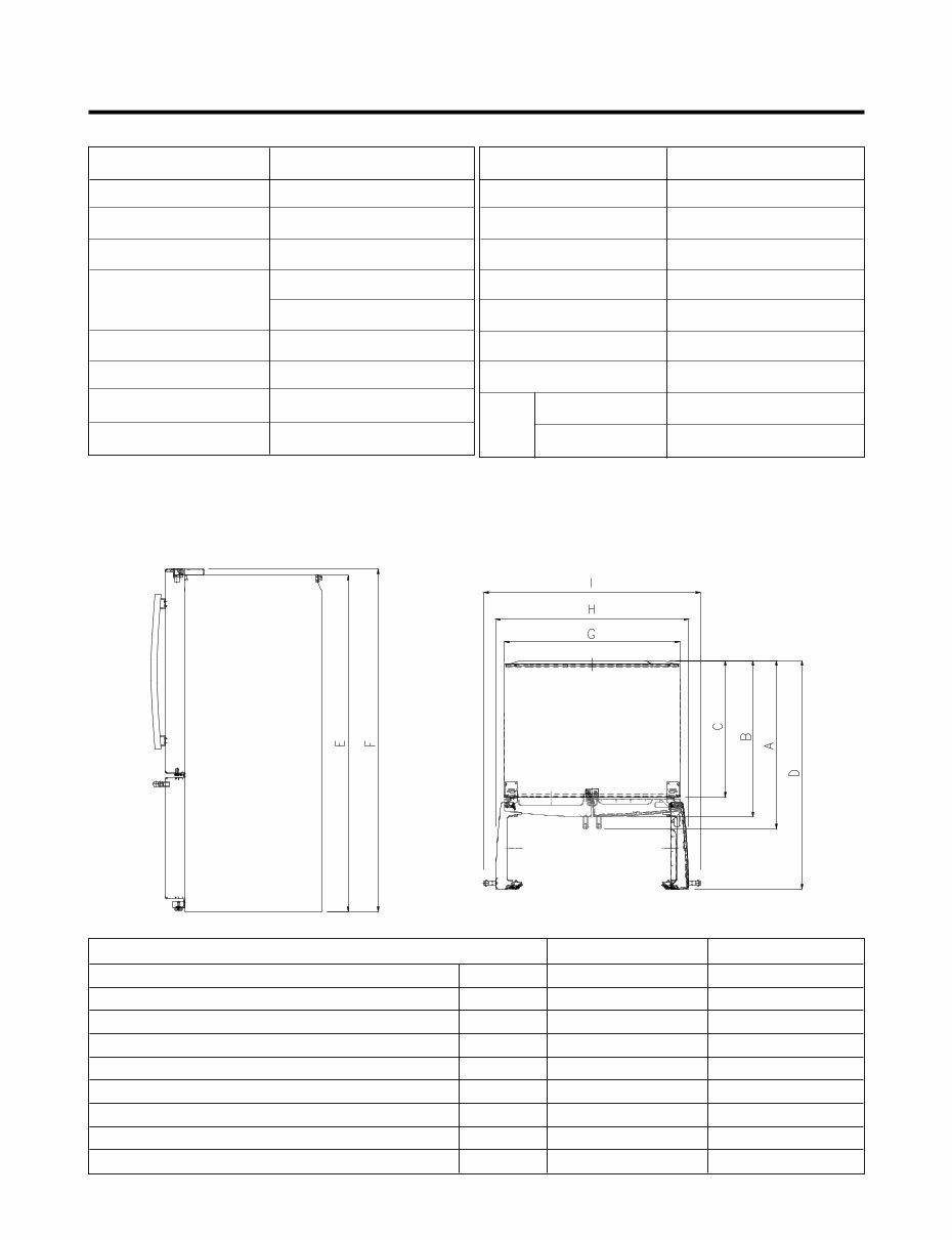
1. SPECIFICATIONS - 3 - ITEMS SPECIFICATIONS DOOR DESIGN Side Rounded COOLING SYSTEM Fan Cooling TEMPERATURE CONTROL Micom Control Full Automatic DEFROSTING SYSTEM Heater Defrost DOOR FINISH PCM, VCM, Stainless HANDLE TYPE Bar INNER CASE ABS Resin INSULATION Polyurethane Foam ITEMS SPECIFICATIONS VEGETABLE TRAY Opaque Drawer Type COMPRESSOR PTC Starting Type EVAPORATOR Fin Tube Type CONDENSER Wire Condenser REFRIGERANT R-134a (115 g) LUBRICATING OIL ISO10 (280 ml) DEFROSTING DEVICE SHEATH HEATER LAMP REFRIGERATOR 60 W (2 EA) FREEZER 60 W (1 EA) Description LFC21760** LFC25760** Depth w/ Handles A 30 in. 34 1/4 in. Depth w/o Handles B 27 1/2 in. 31 3/4 in. Depth w/o Door C 23 5/8 in. 27 7/8 in. Depth (Total with Door Open) D 42 1/4 in. 46 1 /2 in. Height to Top of Case E 68 3/8 in. 68 3/8 in. Height to Top of Door Hinge F 69 3/4 in. 69 3/4 in. Width G 35 3/4 in. 35 3/4 in. Width (door open 90 deg. w/o handle) H 39 1/4 in. 39/1/4 in. Width (door open 90 deg. w/ handle) I 44 1/4 in. 44 1/4 in. DIMENSIONS
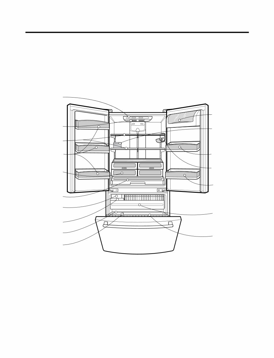
2. PARTS IDENTIFICATION - 4 - Egg Box Digital Sensor Control Refrigerator Light Shelves Optibin Crisper Keeps fruits and vegetable fresh and crisp Customcube Icemaker Glide'N'Serve Ice Bin Durabase Divider Pullout Drawer Tilt- Out Door Basket Modular Door Bin Modular Door Bin Bottle Holder Dairy Bin Modular Door Bin (Tilting-LFC25760** Only)
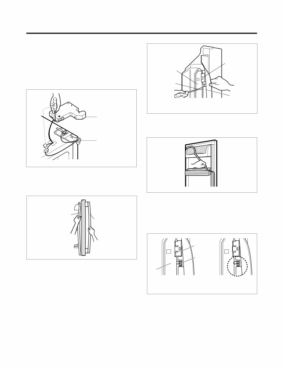
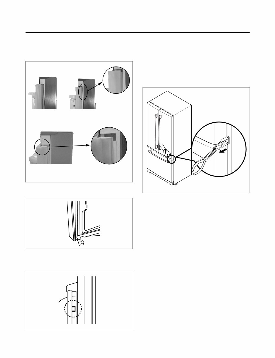
3-1 DOOR ● Refrigerator door 1. Remove the top hinge cover and disconnect the wire harness. 2. Remove the ground screw. 3. Rotate the lever hinge and lift off hinge. 4. Lift off the refrigerator door. 5. Replace in the reverse order. ● Door gasket removal 1. Remove door frame cover Starting at top of cover and working down, snap cover out and away from door. 2. Remove gasket bracket clips There are two clips on each door. Start bracket removal near one of the middle clips. 1) Pull gasket back to expose gasket bracket clip and door frame. 2) Insert a flat tip screwdriver into seam between gasket bracket and door frame and pry back until clips snaps out. 3) Continue prying back along seam until all clips snap out. 3. Remove gasket Pull gasket free from gasket channel on the three remaining sides of door. ● Door gasket replacement 1. Insert gasket bracket clips 1) Insert gasket bracket edge beneath door frame edge. 2) Turn upper gasket bracket spring so that both spring ends are in the door channel. 3) Push in clip until you hear it snap securely into place. 4) Push in remaining two clips until you hear each snap securely into place. Note: Make sure that no part of gasket bracket edge protrudes from beneath door frame edge. 3. DISASSEMBLY - 5 - HINGE HINGE COVER Figure 1 Frame Cover Handle Door Frame Gasket Bracket Clip Flat Tip Screwdriver Gasket Bracket Figure 2 Figure 3 Figure 4 Door Frame Gasket Bracket Clip Spring Incorrect Correct Figure 5
2. Insert gasket into channel 1) Snap gasket assembly into the door bracket. Inserting the gasket assembly into the bracket door 2) Press gasket into channels on the three remaining sides of door. 3. Replace door frame cover Starting at top of cover and working down, snap the cover back into door. 3-2 DOOR ALIGNMENT If the space between your doors is uneven, follow the instructions below to align the doors: 1. With one hand, lift the door you want to raise at middle hinge. 2. With other hand, use pliers to insert snap ring as shown. 3. Insert additional snap rings until the doors are aligned. (Three snap rings are provided with the product.) - 6 - Figure 7 Figure 8 Figure 9 Figure 6 Correct Incorrect
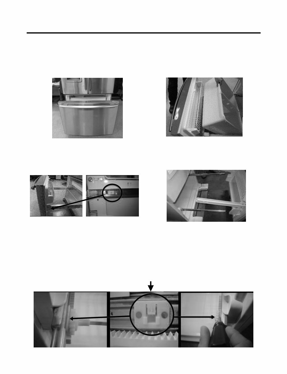
- 7 - 3-3 HOW TO REMOVE AND REINSTALL THE PULLOUT DRAWER 3-3-1 FOLLOW STEPS TO REMOVE Step 1) Open the freezer door. Step 3) Remove the two screws from the guide rails (one from each side). Step 2) Remove the lower basket. Step 4) Lift the freezer door up to unhook it from the rail support and remove. Pull both rails to full extension. Step 5) First: Remove the gear from the left side first by releasing the tab behind the gear, place a screwdriver between the gear and the tab and pull up on the gear. Second: Remove the center rail. Third: Remove the gear from the right side by following the same steps for the left side. NOTE: THIS TAB MUST BE PUSHED IN TO RELEASE THE GEAR.
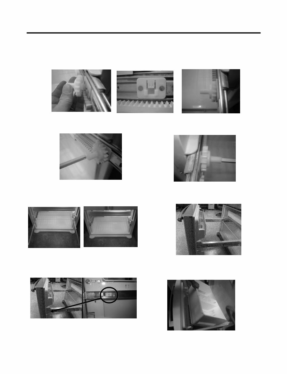
3-3-2 FOLLOW STEPS TO REINSTALL Step 1) Reinstall the right side gear into the clip. Step 2) Insert the rail into the right side gear. Gears do not need to be perpendicular to each other. Step 4) The rail system will align itself by pushing the rails all the way into the freezer section. Pull the rails back out to full extension. Step 6) Reinstall the two screws into the guide rails (one from each side). Step 3) Insert the rail into the left side gear, and insert the gear into the clip. Step 5) Reinstall the freezer door by inserting the rail tabs into the guide rail. Step 7) Reinstall the lower basket, and close the freezer door. - 8 -
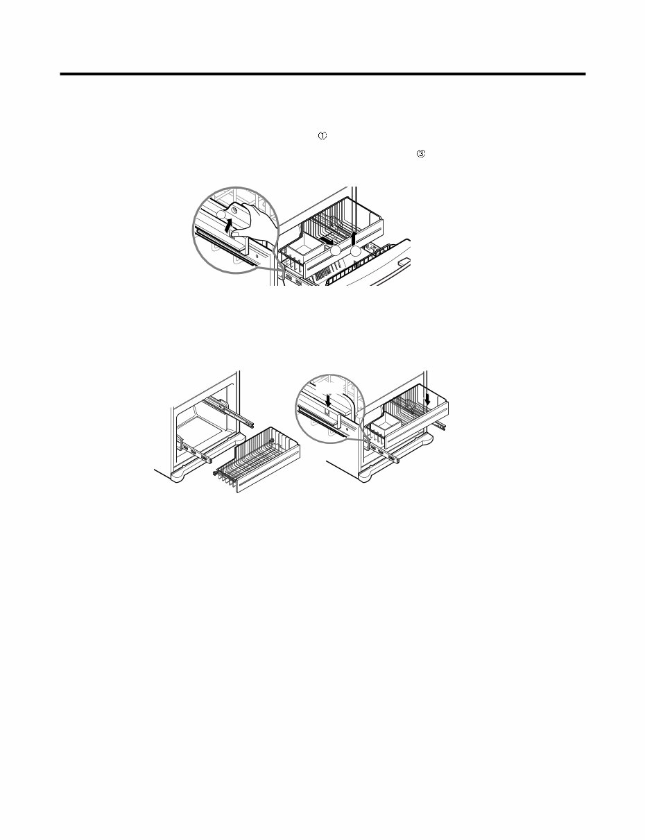
3-3-3 PULL OUT DRAWER To separate the drawer, push the front left and right hooks in direction to pull up and remove. Then gently lift the gear part of rear left and right side of the drawer and pull it out in direction. To install, reposition the gear part of rear left and right side of the drawer after pulling out both rails as much as possible, and gently push down both left and right side while checking the hook on the front part. 2 3 1 Hook - 9 -
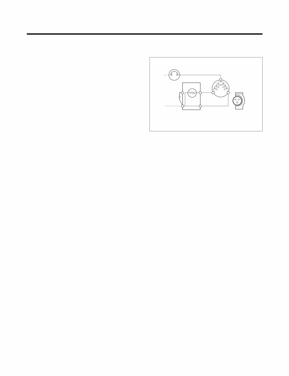
4-1 COMPRESSOR 4-1-1 Role The compressor intakes low temperature and low pressure gas from the evaporator of the refrigerator and compresses this gas to high-temperature and high-pressure gas. It then delivers the gas to the condenser. 4-1-2 Composition The compressor includes overload protection. The PTC starter and OLP (overload protector) are attached to the outside of the compressor. Since the compressor is manufactured to tolerances of 1 micron and is hermetically sealed in a dust and moisture-free environment, use extreme caution when repairing it. 4-1-3 Note for usage (1) Be careful not to allow over-voltage and over-current. (2) If compressor is dropped or handled carelessly, poor operation and noise may result. (3) Use proper electric components appropriate to the particular compressor in your product. (4) Keep compressor dry. If the compressor gets wet (in the rain or a damp environment) and rust forms in the pin of the Hermetic Terminal, poor operation and contact may result. If the hermetic connector rusts out or fails, refrigerant and oil will be expelled into the contact area, probably resulting in smoke and fire. (5) When replacing the compressor, be careful that dust, humidity, and soldering flux don’t contaminate the inside of the compressor. Contamination in the cylinder may cause noise, improper operation or even cause it to lock up. 4-2 PTC-STARTER 4-2-1 Composition of PTC-Starter (1) PTC (Positive Temperature Coefficient) is a no-contact semiconductor starting device which uses ceramic material consisting of BaTiO3. (2) The higher the temperature is, the higher the resistance value. These features are used as a starting device for the motor. 4-2-2 Role of PTC-Starter (1) The PTC is attached to the sealed compressor and is used for starting the motor. (2) The compressor is a single-phase induction motor. Durign the starting operation, the PTC allows current flow to both the start winding and main winding. 4-2-3 PTC-Applied circuit diagram ● Starting method for the motor 4-2-4 Motor restarting and PTC cooling (1) It requires approximately 5 minutes for the pressure to equalize before the compressor can restart. (2) The PTC device generates heat during operation. Therefore, it must be allowed to cool before the compressor can restart. 4-2-5 Relation of PTC-Starter and OLP (1) If the compressor attempts to restart before the PTC device is cooled, the PTC device will allow current to flow only to the main winding. (2) The OLP will open because of the overcurrent condition. This same process will continue (3 to 5 times) when the compressor attempts to restart until the PTC device has cooled. The correct OLP must be properly attached to prevent damage to the compressor. Parts may appear physically identical but could have different electrical ratings. Replace parts by part number and model number. Using an incorrect part could result in damage to the product, fire, injury, or possibly death. 4-2-6 Note for using the PTC-Starter (1) Be careful not to allow over-voltage and over-current. (2) Do not drop or handle carelessly. (3) Keep away from any liquid. If liquid such as oil or water enters the PTC, PTC materials may fail due to breakdown of their insulating capabilities. (4) If the exterior of the PTC is damaged, the resistance value may be altered. This can cause damage to the compressor and result in a no-start or hard-to-start condition. (5) Always use the PTC designed for the compressor and make sure it is properly attached to the compressor. Parts may appear physically identical but could have different electrical ratings. Replace parts by part number and model number. Using an incorrect part could result in damage to the product, fire, injury, or possibly death. 4. ADJUSTMENT - 10 - PTC STARTER SEALED TERMINAL COMPRESSOR MOTOR C M S M 3 6 5 2 S N L1 OVERLOAD PROTECTOR Resistance Starter Capacitor Running PTC Figure 17
Why replace when you can upgrade or repair? This service and repair manual is used by the Official Certified LG Technicians. It will help you to troubleshoot and repair your refrigerator!
Contents:
Specifications
Parts Identification
Disassembly
Adjustments
Circuit Diagram
Trouble Shooting
Description of Functions
Exploded View
This manual covers the following models:
LG LFC21760ST
LG LFC25760SW
LG LFC25760SB
LG LFC25760TT
LG LFC25760ST
This service manual is very detailed and illustrated with pictures and step-by-step instructions on how to repair/service this device the best way there is!
Please note this is the OFFICIAL service and repair manual in .PDF format, no scanned-in or bootlegged copy. This manual is made in the highest resolution, so when you print the pages you need it is all in great quality!
You can easily print this service manual from any printer and any computer!
***INSTANT access*** After your payment, you will have instant access to your manual. No shipping fee, no waiting on postal delivery, you can start doing your repairs today!
Specifications
Language: English
Format: .PDF
Pages: 46
Platform: Windows and MAC
Looking for a service manual but can't find it anywhere? Please contact us with your request! As you can see we've got the largest & most comprehensive service manual database out there, so a good chance we can help you out!
Recently Viewed
5,521,897Happy Clients
2,594,462eManuals
1,120,453Trusted Sellers
15Years in Business
Price:
Actual Price:
LG LFC21760 LFC25760 Series Service Manual & Repair Guide