CAUTIO N PLEASE READ CAREFULLY THE SAFETY PRECAUTIONS OF THIS BOO K BEFORE CHECKING OR OPERATING THE REFRIGERATO R . REFRIGERATOR SERVICE MANUAL http://biz.lgservice.co m MODEL:GC-L207G + GSL325PZYZ
WARNINGS AND PRECAUTIONS FOR SAFETY ........................................................................................... ..................... 3 4 1 . . . . . . . . . . . . . . . . . . . . . . . . . . . . . . . . . . . . . . . . . . . . . . . . . . . . . . . . . . . . . . . . . . . . . . . . . . . . . . . . . . . . . . . . . . . . . . . . . . . . . . . . . . . . . . . . . . . . . . . . . . . . . . . . . . . . . . . . . . . . . . . . . . . . . . . . . . . . . . . . . . . S N O I T A C I F I C E P S PARTS IDENTIFICATION ......................................................................................................................................................15 HOW TO INSTALL THE REFRIGERATOR .......................................................................................................................... 16 HOW TO ADJUST DOOR HEIGHT OF THE REFRIGERATOR ........................................................................................ 16 HOW TO INSTALL WATER PIPE........................................................................................................................................17 HOW TO CONTROL THE AMOUNT OF WATER SUPPLIED TO THE ICEMAKER ......................................................... 21 MICOM FUNCTION .............................................................................................................................................................. 23 EXPLATION FOR MICOM CIRCUIT..................................................................................................................................... 26 EXPLANATION FOR PWB CIRCUIT ................................................................................................................................. 26 COMPENSATION CIRCUIT FOR WEAK-COLD, OVER-COLD AT FREEZING ROOM.................................................... 34 PWB PARTS DRAWING AND LIST ................................................................................................................................... 37 PWB CIRCUIT DIAGRAM .................................................................................................................................................. 38 ICE MAKER AND DISPENSER WORKING PRINCIPLES AND RE PAIR ........................................................................... 41 WORKING PRINCIPLES.................................................................................................................................................... 41 FUNCTION OF ICE MAKER .............................................................................................................................................. 42 ICE MAKER TROUBLESHOOTING................................................................................................................................... 45 ICE MAKER CIRCUITS ...................................................................................................................................................... 46 CIRCUIT ................................................................................................................................................................................ 47 MICOM ERROR CODE..........................................................................................................................................................48 TROUBLE DIAGNOSIS ........................................................................................................................................................ 74 TROUBLE SHOOTING ...................................................................................................................................................... 74 FAULTS ............................................................................................................................................................................ 84 COOLING CYCLE HEAVY REPAIR ................................................................................................................................. 101 HOW TO DEAL WITH CLAIMS ........................................................................................................................................ 108 HOW TO DISASSEMBLE AND ASSEMBLE ..................................................................................................................... 113 DOOR ............................................................................................................................................................................... 113 HANDLE ........................................................................................................................................................................... 114 SHROUD, GRILLE FAN ................................................................................................................................................... 114 ICEMAKER ....................................................................................................................................................................... 114 DISPENSER ..................................................................................................................................................................... 115 EXPLODED VIEW .............................................................................................................................................................. 118 CONTENTS - 2 - COMPRESSOR .................................................................................................................................................................. ....................................... .................................................. 4 8 Heavy Repair Method of Refrigerator by Application of Refrigerant
Please observe the following safety precautions in order to use safely and correctly the refrigerator and to prevent accident and danger during repair. 1. Be care of an electric shock. Disconnect power cord from wall outlet and wait for more than three minutes before replacing PWB parts. Shut off the power whenever replacing and repairing electric components. 2. When connecting power cord, please wait for more than five minutes after power cord was disconnected from the wall outlet. 3. Please check if the power plug is pressed down by the refrigerator against the wall. If the power plug was damaged, it may cause fire or electric shock. 4. If the wall outlet is over loaded, it may cause fire. Please use its own individual electrical outlet for the refrigerator. 5. Please make sure the outlet is properly earthed, particularly in wet or damp area. 6. Use standard electrical components when replacing them. 7. Make sure the hook is correctly engaged. Remove dust and foreign materials from the housing and connecting parts. 8. Do not fray, damage, machine, heavily bend, pull out, or twist the power cord. 9. Please check the evidence of moisture intrusion in the electrical components. Replace the parts or mask it with insulation tapes if moisture intrusion was confirmed. 10. Do not touch the icemaker with hands or tools to confirm the operation of geared motor. 11. Do not let the customers repair, disassemble, and reconstruct the refrigerator for themselves. It may cause accident, electric shock, or fire. 12. Do not store flammable materials such as ether, benzene, alcohol, chemicals, gas, or medicine in the refrigerator. 13. Do not put flower vase, cup, cosmetics, chemicals, etc., or container with full of water on the top of the refrigerator. 14. Do not put glass bottles with full of water into the freezer. The contents shall freeze and break the glass bottles. 15. When you scrap the refrigerator, please disconnect the door gasket first and scrap it where children are not accessible. WARNINGS AND PRECAUTIONS FOR SAFETY - 3 -
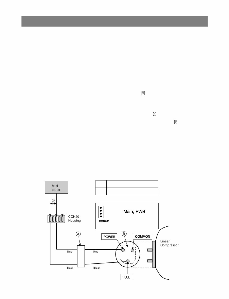
Chapter 8 Compressor 1. Inverter Linear Compressor Check for defect of the inverter linear compressor in following orders: 1-1. Method to Measure Compressor Winding Resistance Normal Determination Criteria The compressor winding resistance can be determined as normal if resistance values show the values as described in below figure when measuring resistance values of the harness (connected with compressor) to connect Connect201(CON201) of the main PWB as shown in below figure. Defect Determination Criteria Check connection status of the Compressor Connection Harness-P(Lead Wire) which is located at the M/C room where resistance values measured at the CON201 Housing are shown as infinite or several hundred . Separate connecting wires of the M/C room (A-point in Figure) and then measure resistance values at the connecting wires again. The compressor can be determined as normal if resistance values are shown as standard resistance value. Check connection status of a harness. (Defect at M/C room connection contact or CON201 Housing contact, short-circuit of harness) Where resistance values measured at A-point are also shown as infinite or several hundred , disassemble a cover PTC of the compressor terminal and check the terminal connecting status at the B-point in Figure. Where there is no failure in the wiring status and resistance values are shown as infinite or several hundred , it may be determined as defect of compressor. Since if there is no failure in resistance values of the compressor, it may be defective Main PWB, replace the Main PCB and check for normal operation of the compressor. When determining any defect through resistance measuring, it can be determined as normal if resistance values show as descried in the below figure by measuring ① power and ③ common terminal resistance values are measured when measuring ① power but measuring is meaningless since they cannot become criteria for determining defect (measuring not required). Caution 1. Be sure to powering off the refrigerator and measure after several minutes has passed. 2. If not accurately measuring resistance, wrong determination may be guided. (Difference of resistance value of several W or so may occur.) COMPRESSOR ● ● ● ● ● -4- Winding resistance value ① 6.0~10.0 Ω (Average: 8Ω)
1-2.Method to Determine Defect of Inverter Linear Drive Determination of Comp Operation Separate the back cover at the rear of refrigerator and determine for possible operation while touching the compressor with the hands with insulation gloves worn. Comp Operation - Determine possible trip by checking operation status if cold air comes out after opening the doors of the R-Room. Protective Logic (Trip) - To protect the compressor from abnormal operation, this logic is used to temporally stop the refrigerator when abnormal operation occurs and to re-operate it after abnormal signal disappears. COMPRESSOR -5- Code Operation Condition OFF Time LED On/Off FCT0 5 |Vm, Im|> 2.5V+20% @ COMP off 30s 1 Stroke 10 |Stroke|>17mm 60s 2 Lock 25 |AC Current|>1.5A & |Stroke|<5.5mm 150s 5 Current 30 |Current|>4Ap 360s 6 IPM 35 vbu08_fo_trip != 0 20S 7 Communication Error - Checksum error - 8
Fuse Inspection - Visually inspect for fuse broken. - When a fuse is destroyed, visually inspect for breaking of IPM and additionally check it with a multi-test. Inverter Parts Inspection - Visually inspect for breaking of IPM and additionally check it with a multi-test (check for short). Bridge Diode Inspection - Bridge diode is considered as destroyed if value of 10W or less is shown in every case when measuring resistance with a multi-test for 2 terminals of 4 diode terminals. ※ Power should be turned on again after checking all parts because series of detects may occur when powering on in a simple parts defect status for parts defect related with an inverter. COMPRESSOR -6-
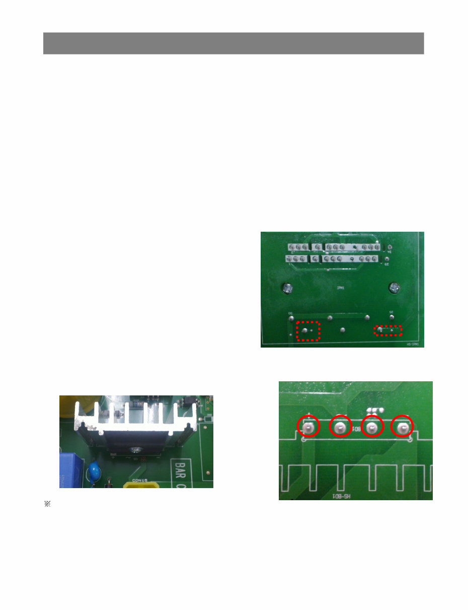
Parts Defect Determination in Power On Status Parts Defect Determination in Power On Status Check of Power Application -Check that supply power of +15V, +8V used as supply power of digital circuits is normally applied. COMPRESSOR +15V +7v Measuring part D202 Pin2-GND D203 Pin2-GND Normal 13V-15.5V 5V-9V Defect 13V or less 5V or less Measures Replace board Replace board -7-
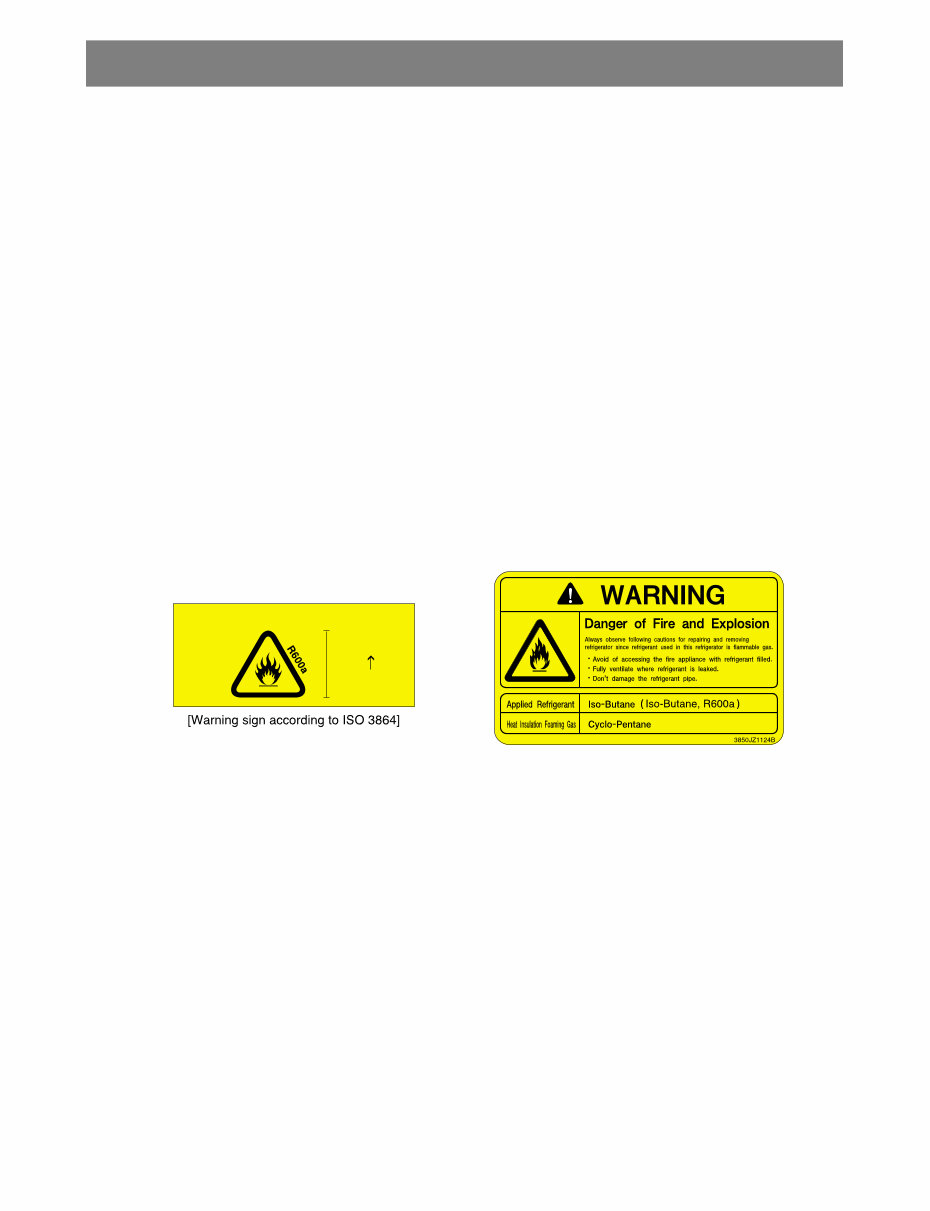
Chapter 9 Heavy Repair Method of Refrigerator by Application of Refrigerant 1. Outline 1-1. Checkpoints before Heavy Repair Open the Cover ASM, Back-M/C of refrigerator and check the type of refrigerant indicated on a compressor before starting work.A yellow label is adhered to the compressor for the refrigerator using R600a as refrigerant. 1-2. Features of R600a Refrigerant Non-polar natural gas refrigerant (CH(CH3)3) Since R600a is same series as butane gas, there is danger of fire when discharged into air at appropriate concentration (extreme handling is required for heavy repair of cycle). Explosion concentration: .8% ~ 8.4%/Vol. Burning temperature: 494 ℃ 1-3. Features of R600a Refrigerator With refrigerant quantity of 60% or so for the refrigerator using R134a as refrigerant Large vacuum level at suction pressure (at low pressure side) COMP capacity of the refrigerator using R609a as refrigerant is large by 1.7 times than that of the refrigerator using R134a. Labels as in Figure are displayed at the compressor of a refrigerant for R600a and the back plate of refrigerator. 1-4. Location and Environment for Heavy Repair Check that drafting and air ventilation are well done at a working area and perform work after making drafting and air ventilation smooth (use refrigerant return bag indoors). Check that there are fire appliances or heating source around the working area and then remove them before work. Since R600a refrigerant is very inflammable, they should not be discharged indoors. Be sure to follow heavy repair SVC procedures during work. 1-5. Heave Repair Work Tool R600a refrigerant Bombe Pinch Pliers Refrigerant Discharge Hose Refrigerant Return Bag Vacuum Pump Handy Welding Machine Charging Tube Leakage Tester Drier Heavy Repair Method of Refrigerator by Application of Refrigerant Insulation Blowing Gas : Cyclopentane 15mm ● ● ● ● ● ● ● ● ● ● ● ● ● ● ● ● ● ● ● ● -8-
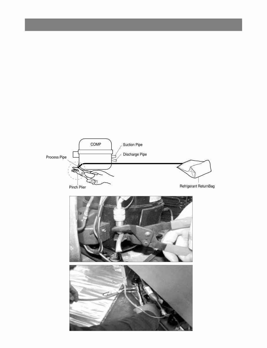
2. Heavy Repair SVC Method For the heaver repair of R600a type of refrigerator, perform work according to following SVC method. 2-1. Returnof Refrigerator Refrigerant Required equipment: Pinch pliers, refrigerant discharging hose, refrigerant returnbag Take power cords out and remove power between 6sec through 12sec after powering ON to open all both sides of 3way valve. Leave doors of a refrigerator so that they are not closed. Connect pinch pliers with a refrigerant discharging hose. Place the outlet of a refrigerant discharging hose outside. (Remove fire appliances or heating sources near a refrigerant discharging hose.) Always use a refrigerant returnbag for working at the contained space. Bore the charging pipe of a compressor with pinch pliers. (Remove fire appliances or heating sources near a refrigerator.) Perform refrigerant discharge for more than 7 minutes. Heavy Repair Method of Refrigerator by Application of Refrigerant ● ● ● ● ● ● ● -9-
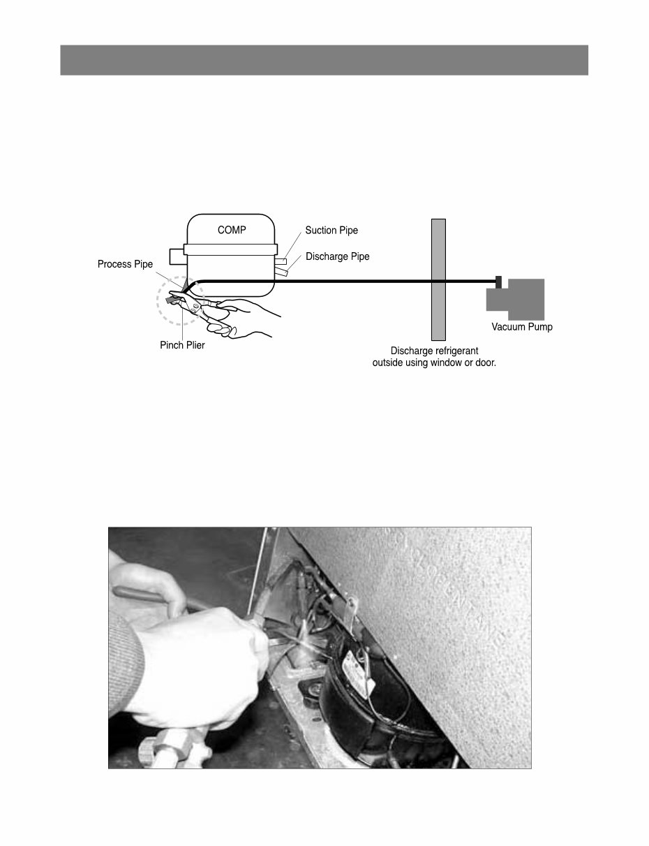
2-2. Returnof Remained Refrigerant Required equipment: Pinch pliers, hose for refrigerant recovery, vacuum pump If refrigerant returntime of 7 minutes has passed, connect a vacuum pump at the ends of a refrigerant returnhose outdoor. (Vacuum pump must operate outdoor.) Operate a vacuum pump in order to returnrefrigerant remained in the pipe. Vacuum working time should be for more than 10 minutes. 2-3. Welding Repair Step Required equipment: Simple welding machine Remove pinch pliers if remaining refrigerant returnis completed. Cut the front part of a process pipe with a cutter. (Check that remaining refrigerant comes out.) Perform welding work such as replacement of compressor and dryer, or repair of leakage part. (Be cautious of fire during welding work.) Heavy Repair Method of Refrigerator by Application of Refrigerant ● ● ● ● ● ● -10-
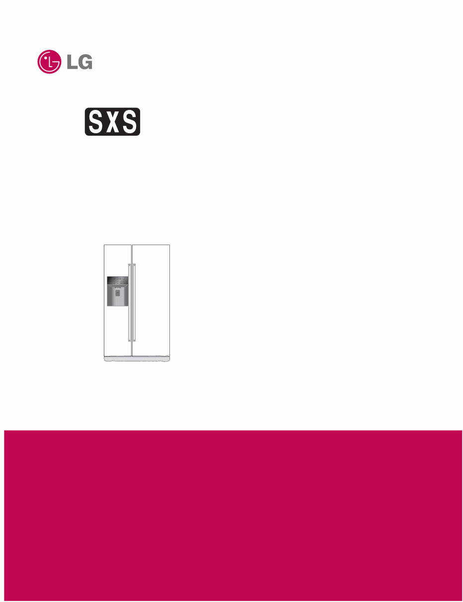
The LG GSL325PZYZ Side-by-Side Refrigerator official service manual is an essential resource for both professional technicians and DIY enthusiasts. This comprehensive manual provides detailed insights into product specifications, parts identification, installations, disassembly instructions, troubleshooting, adjustment procedures, circuit diagram, printed wiring board, description of functions & circuits, error codes, cooling cycle heavy repair, ice maker working principles & repair, and exploded views.
Featuring high-resolution illustrations and step-by-step instructions, this official service and repair manual ensures the best possible guidance for servicing and repairing the refrigerator. It is available in English and comes in a printable PDF format, allowing easy access from any computer or printer. With instant access after payment, there are no shipping fees or waiting for postal delivery, enabling prompt initiation of repairs.