CAUTION PLEASE READ CAREFULLY THE SAFETY PRECAUTIONS OF THIS BOOK BEFORE CHECKING OR OPERATING THE REFRIGERATOR. SERVICE MANUAL http://biz.lgservice.com Ref No : GS3159**A* GS3159**B* GS3159**C* GS3159**D* Ref No : GS3159**E* GS3159**F* GS3159**G* GS3159**H* Ref No : GS3159**J*
WARNINGS AND PRECAUTIONS FOR SAFETY .................................................................................................................................... 3 SPECIFICATIONS.................................................................................................................................................................................... 5 PARTS IDENTIFICATION ........................................................................................................................................................................ 6 HOW TO INSTALL THE REFRIGERATOR ................................................................................................................................................ 8 HOW TO ADJUST DOOR HEIGHT OF THE REFRIGERATOR .................................................................................................................................................. 8 CONNECTION TO MAIN WATER SUPPLY................................................................................................................................................................................... 9 HOW TO CONTROL THE AMOUNT OF WATER SUPPLIED TO THE ICEMAKER ........................................................................................................... 13 MICOM FUNCTION ............................................................................................................................................................................. 15 MICOM CODE ERROR .......................................................................................................................................................................... 21 ICE MAKER AND DISPENSER WORKING PRINCIPLES AND REPAIR .................................................................................................. 52 WORKING PRINCIPLES................................................................................................................................................................................................................... 52 FUNCTION OF ICE MAKER ........................................................................................................................................................................................................... 53 ICE MAKER TROUBLESHOOTING............................................................................................................................................................................................... 56 ICE MAKER CIRCUITS ..................................................................................................................................................................................................................... 57 CIRCUIT ............................................................................................................................................................................................... 58 TROUBLE DIAGNOSIS ........................................................................................................................................................................ 59 TROUBLE SHOOTING ................................................................................................................................................................................................................... 59 FAULTS .............................................................................................................................................................................................................................................. 69 COOLING CYCLE HEAVY REPAIR .............................................................................................................................................................................................. 86 HOW TO DEAL WITH CLAIMS ................................................................................................................................................................................................... 92 HOW TO DISASSEMBLE AND ASSEMBLE ......................................................................................................................................... 97 DOOR ................................................................................................................................................................................................................................................ 97 HANDLE ........................................................................................................................................................................................................................................... 98 SHROUD, GRILLE FAN ................................................................................................................................................................................................................. 98 ICEMAKER ........................................................................................................................................................................................................................................ 98 DISPENSER .................................................................................................................................................................................................................................... 103 VALVE ASSEMBLY WATER ....................................................................................................................................................................................................... 102 REFRIGERATOR DOOR .............................................................................................................................................................................................................. 101 CASE ASSEMBLY PUMP ............................................................................................................................................................................................................ 101 FAN AND FAN MOTOR ............................................................................................................................................................................................................. 100 WATER VALVE ................................................................................................................................................................................................................................ 99 HOME BAR .................................................................................................................................................................................................................................... 105 EXPLODED VIEW ............................................................................................................................................................................. 106 CONTENTS - 2 - SERVICING PRECAUTIONS ....................................................................................................................................................................... 4 TROUBLE DIAGNOSIS ......................................................................................................................................................................... 22
Please observe the following safety precautions in order to use safely and correctly the refrigerator and to prevent accident and danger during repair. 1. Be care of an electric shock. Disconnect power cord from wall outlet and wait for more than three minutes before replacing PWB parts. Shut off the power whenever replacing and repairing electric components. 2. When connecting power cord, please wait for more than five minutes after power cord was disconnected from the wall outlet. 3. Please check if the power plug is pressed down by the refrigerator against the wall. If the power plug was damaged, it may cause fire or electric shock. 4. If the wall outlet is over loaded, it may cause fire. Please use its own individual electrical outlet for the refrigerator. 5. Please make sure the outlet is properly earthed, particularly in wet or damp area. 6. Use standard electrical components when replacing them. 7. Make sure the hook is correctly engaged. Remove dust and foreign materials from the housing and connecting parts. 8. Do not fray, damage, machine, heavily bend, pull out, or twist the power cord. 9. Please check the evidence of moisture intrusion in the electrical components. Replace the parts or mask it with insulation tapes if moisture intrusion was confirmed. 10. Do not touch the icemaker with hands or tools to confirm the operation of geared motor. 11. Do not let the customers repair, disassemble, and reconstruct the refrigerator for themselves. It may cause accident, electric shock, or fire. 12. Do not store flammable materials such as ether, benzene, alcohol, chemicals, gas, or medicine in the refrigerator. 13. Do not put flower vase, cup, cosmetics, chemicals, etc., or container with full of water on the top of the refrigerator. 14. Do not put glass bottles with full of water into the freezer. The contents shall freeze and break the glass bottles. 15. When you scrap the refrigerator, please disconnect the door gasket first and scrap it where children are not accessible. WARNINGS AND SAFETY PRECAUTIONS - 3 -
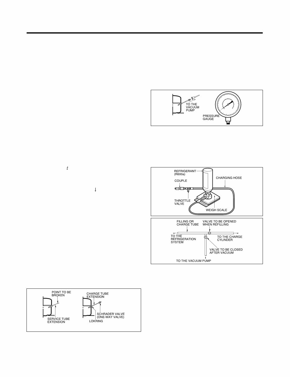
SERVICING PRECAUTIONS Features of refrigerant (R600a) • Achromatic and odor less gas. • Flammable gas and the ignition (explosion) at 494°C. • Upper/lower explosion limit: 1.8%~8.4%/Vol. Features of the R600a refrigerator • Charging of 60% refrigerant compared with a R134a model. • The suction pressure is below 1bar (abs) during the operation. • Because of its low suction pressure, the external air may flow in the cycle system when the refrigerant leak, and it causes malfunction in the compressor. • The displacement of compressor using R600a must be at least 1.7 times larger than that of R134a. • Any type of dryer is applicable (XH-5, 7, 9). • The EVAPORATOR or any other cycle part that has welding joint is hidden in the foam. (If not hidden inside, the whole electric parts must be tested with the LEAKAGE TEST according to the IEC Standard.) • The compressor has label of the refrigerant R600a. • Only the SVC man must have an access to the system. After the refrigerant (R600a) is completely discharged, repair any defective parts and replace the dryer. At any case you must use the LOKRING for connecting or replacing any part in the cycle (No Fire, No Welding). Connect the Schrader valve to pump with the coupler. And then turn the pump on for vacuum state (Figure 3). Let the pump run until the low- pressure gauge indicates the vacuum (gauge pressure 0, absolute pressure -1atm or -760mmHg). Recommended vacuum time is 30 min. Charge the N2 gas in order to check for leakage from welding points and the LOKRING. If leakages are found, repair the defects and repeat the vacuum process. After the system is completely vacuumed, fill it with the refrigerant R600a up to what has been specified at your refrigerator Name Plate. The amount of refrigerant (R600a) must be precisely measured within the error of ±2g by an electron scale (Figure 4). If you use the manifold connected with both the refrigerant (R600a) cylinder and the vacuum pump simultaneously, make sure the pump valve is closed (Figure 5). Connect the charging hose (that is connected to the refrigerant (R600a) cylinder) to the Schrader valve installed on the service tube. Then, charge the refrigerant (R600a) by controlling the Throttle valve. When you do so, do not fully open the Throttle valve because it may make damage to the compressor. Gradually charge the refrigerant (R600a) by changing open and close the Throttle Valve (5g at each time). The charging hose must use a one-way valve to prevent the refrigerant refluence. Close the Schrader valve cap after the refrigerant (R600a) is completely recharged. After you completely recharge the refrigerant (R600a), perform the leakage test by using a portable leakage detector or soapy water. Test the low pressure (suction) parts in compressor off time and high pressure parts in compressor on time. If the leakages are found, restart from the refrigerant (R600a) discharging process and repairs defects of leaks. After the leakage test, check the temperature of each parts of the cycle. Check with hands if the CONDENSER and the case (HOT-LINE pipe) that is contacted to the door gasket are warm. Confirm that frost is uniform distributed on the surface of the EVAPORATOR. Installation place • Must be well ventilated. • Must be 20 m 3 or larger. • Must be no-smoking area. • No ignitable factors must be present. Utilities • Refrigerant cylinder (MAX NET 300g) • Manometer • Vacuum pump (600 /min) • Piercing Clamp • Quick coupler • Hoses (5m-1EA, 1m-3EA) • LOKRING • Portable Leakage detector (3g/year ) • Nitrogen cylinder (for leakage test) • Concentration gauge Make sure before Servicing • Refrigerant Confirm the refrigerant by checking Name Plate and the label on the compressor, after opening the COVER ASSEMBLY, BACK-M/C. • If the refrigerant is R600a, you must not weld or apply a heat source. Air Recharging in Compressor Before refilling the refrigerant, you must perform the test according to Chapter 5 (TROUBLESHOOTING CHART). When the defects are found, you must discharge the residual refrigerant (R600a) in the outdoor. For discharging the refrigerant R600a, break the narrow portion of tube extension by hand or with a pipe cutter as shown in Figure 1. Leave it for 30min in outside to stabilize the pressure with ambient. Then, check the pressure by piercing the dryer part with piercing pliers. If the refrigerant is not completely discharged, let the refrigerator alone for more 30min in outside. Attach the service tube installed with a Schrader valve (one- way valve) by using the LOKRING (Figure 2). Then, connect the Schrader valve (one-way valve) to the pump that is connected to the discharging hose leading to the outside. When discharging the residual refrigerant, repeat 3 cycle that includes 3min of the pump running->pump off->30sec of the compressor running. Figure 1 Figure 2 Figure 3 Figure 4 Figure 5 - 4 -
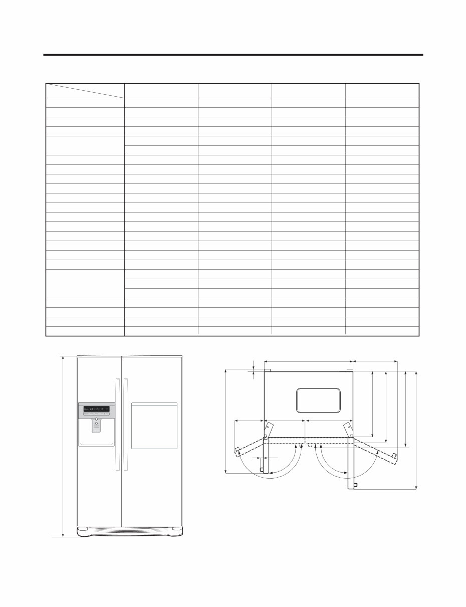
SPECIFICATIONS > w e i V e n a l P < > w e i V t n o r F < 1. Ref No. : DEMENSIONS(mm) 7 0 1 6 0 1 0 2 1 1 2 1 ) g k ( T H G I E W T E N COOLING SYSTEM Fan Cooling Fan Cooling Fan Cooling Fan Cooling TEMPERATURE CONTROL Micom Control Micom Control Micom Control Micom Control DEFROSTING SYSTEM Full Automatic Full Automatic Full Automatic Full Automatic Heater Defrost Heater Defrost Heater Defrost Heater Defros e n a t n e P - o l c y c e n a t n e P - o l c y c e n a t n e P - o l c y c e n a t n e P - o l c y c N O I T A L U S N I COMPRESSOR P.T.C Starting Type P.T.C Starting Type P.T.C Starting Type P.T.C Starting Type EVAPORATOR Fin Tube Type Fin Tube Type Fin Tube Type Fin Tube Type CONDERNSER Wire Condenser Wire Condenser Wire Condenser Wire Condenser REFRIGERANT LUBRICATING OIL FREOL @ 10G(310cc) FREOL @ 10G(310cc) FREOL @ 10G(310cc) FREOL @ 10G(310cc) 3 8 . 0 D I 3 8 . 0 D I 3 8 . 0 D I 3 8 . 0 D I R E I R D CAPILLARY TUBE Molecular Sieve XH-7 Molecular Sieve XH-7 Molecular Sieve XH-7 Molecular Sieve XH-7 FIRST DEFROST 4-5 Hours 4-6 Hours 4-6 Hours 4-6 Hours DEFROST CYCLE 13-15 Hours 13-15 Hours 13-15 Hours 13-15 Hours DEFROSTING DEVICE Heater Sheath Heater Sheath Heater Sheath Heater Sheath ANTI SWEAT HEATER - - - - r e t a e H r e s n e p s i D r e t a e H r e s n e p s i D r e t a e H r a B e m o H - - r e t a e H r a B e m o H ANTI FREEZING HEATER Damper Heater Damper Heater Damper Heater Damper Heater FREEZING LAMP 0.75W(LED) 0.75W(LED) 40W(1EA) 40W(1EA) RERIGERATOR LAMP 0.75W(LED) 0.75W(LED) 40W(1EA) 40W(1EA) - - - - P M A L R E S N E P S I D ITEM Model GS3159**(A-D)* GS3159**(E-H)* GS3159**J* LUBRICATING OIL - FA (LINEAR) COMPRESSOR HTS60MT 10CST (190 cc) HTS60MT 10CST (190 cc) HTS60MT 10CST (190 cc) HTS60MT 10CST (190 cc) 894(W)x725(D)x1753(H) 894(W)x725(D)x1753(H) 894(W)x725(D)x1753(H) 894(W)x725(D)x1753(H) R600A(78g) R600A(78g) R600A(78g) R600A(78g) - 5 - 894 90˚ 90˚ 150˚ 150˚ 602 1753 670 725 1130 386 59 502 1015 7 350 430
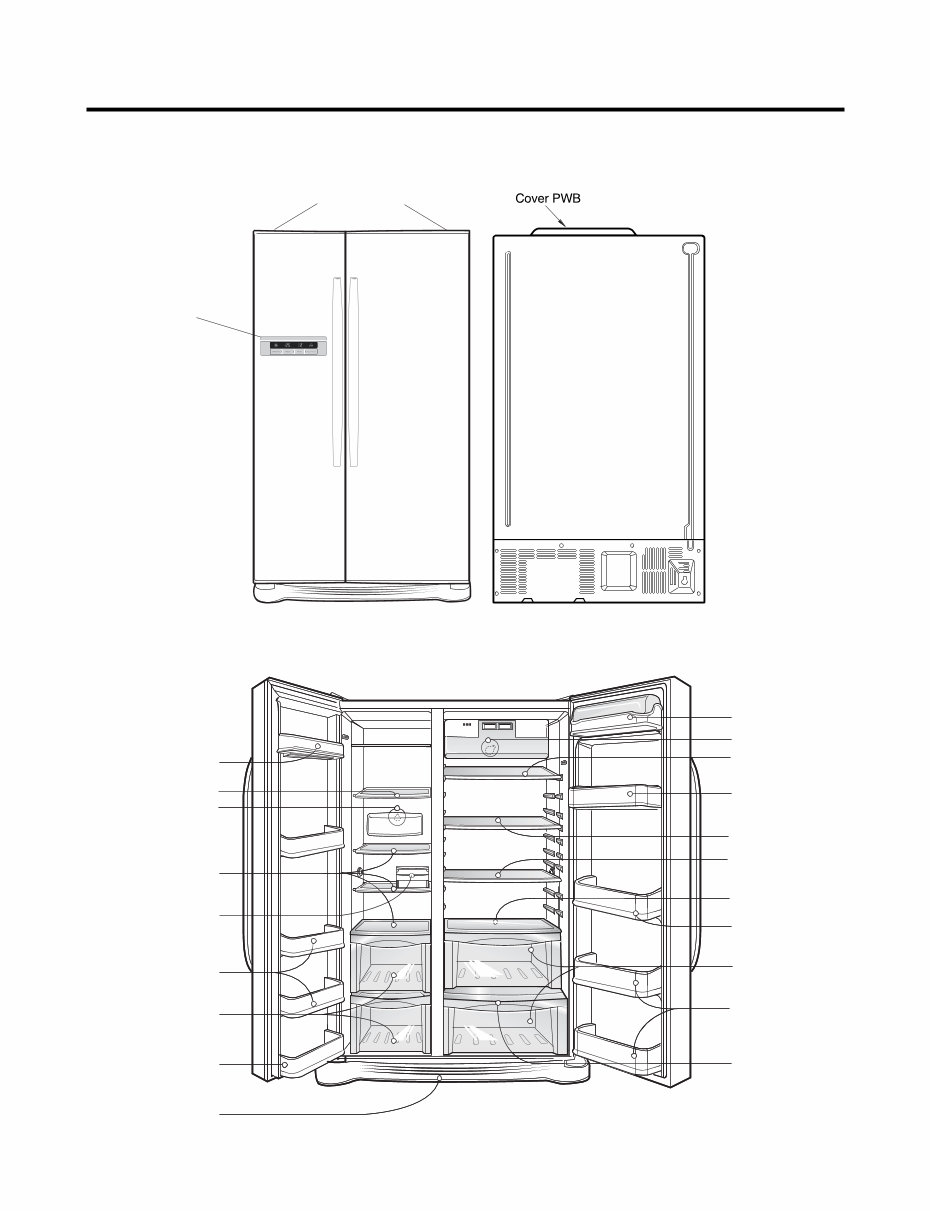
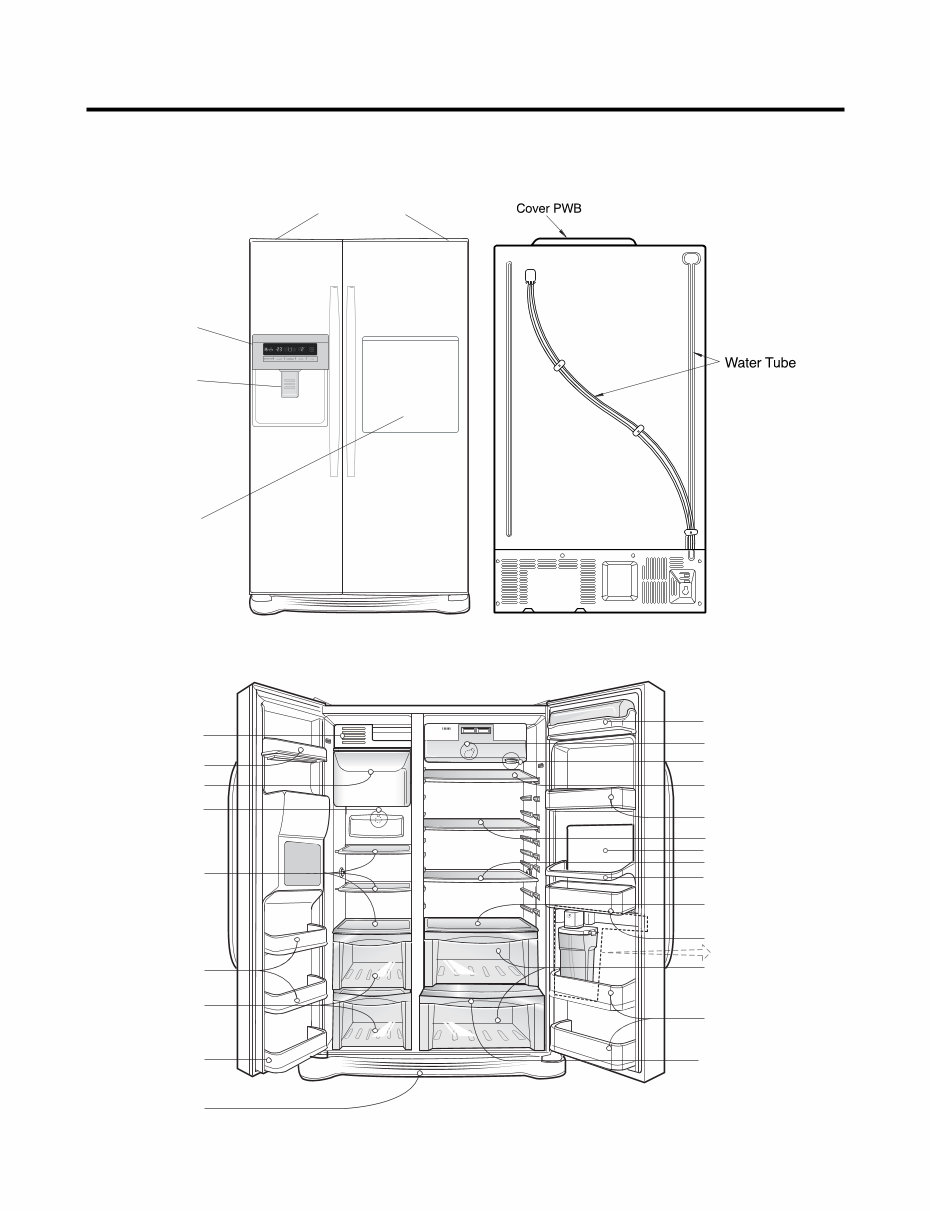
1. Non dispenser model - GS3159**J* PARTS IDENTIFICATION Display Cover Hinge Dairy Corner Shelf Door rack Door rack Door rack Door rack Lower cover Door rack Door rack Vegetable drawer Drawer Shelf Shelf Shelf Shelf Ice Maker Shelf Shelf (folding or normal) Freezer Compartment Refrigerator Compartment Lamp /LED Panel (option) Lamp/LED Lamp (option) - 6 -
PARTS IDENTIFICATION Display Home Bar Ice & Water Dispenser Button (option) Cover Hinge 2. Dispenser model - GS3159**(A-H)* Dairy Corner Space plus Lamp /LED Panel (option) Filter (Internal filter model only) Door rack Door rack Door rack Door rack Lower cover Door rack Door rack Vegetable drawer Drawer Shelf Shelf Shelf Shelf Automatic ice maker Shelf Shelf (folding or normal) Refreshment Centre (optional) Guide pitcher Freezer Compartment Refrigerator Compartment Lamp/LED Lamp (option) No Plumbing Ice & Water (Optional) - 7 -
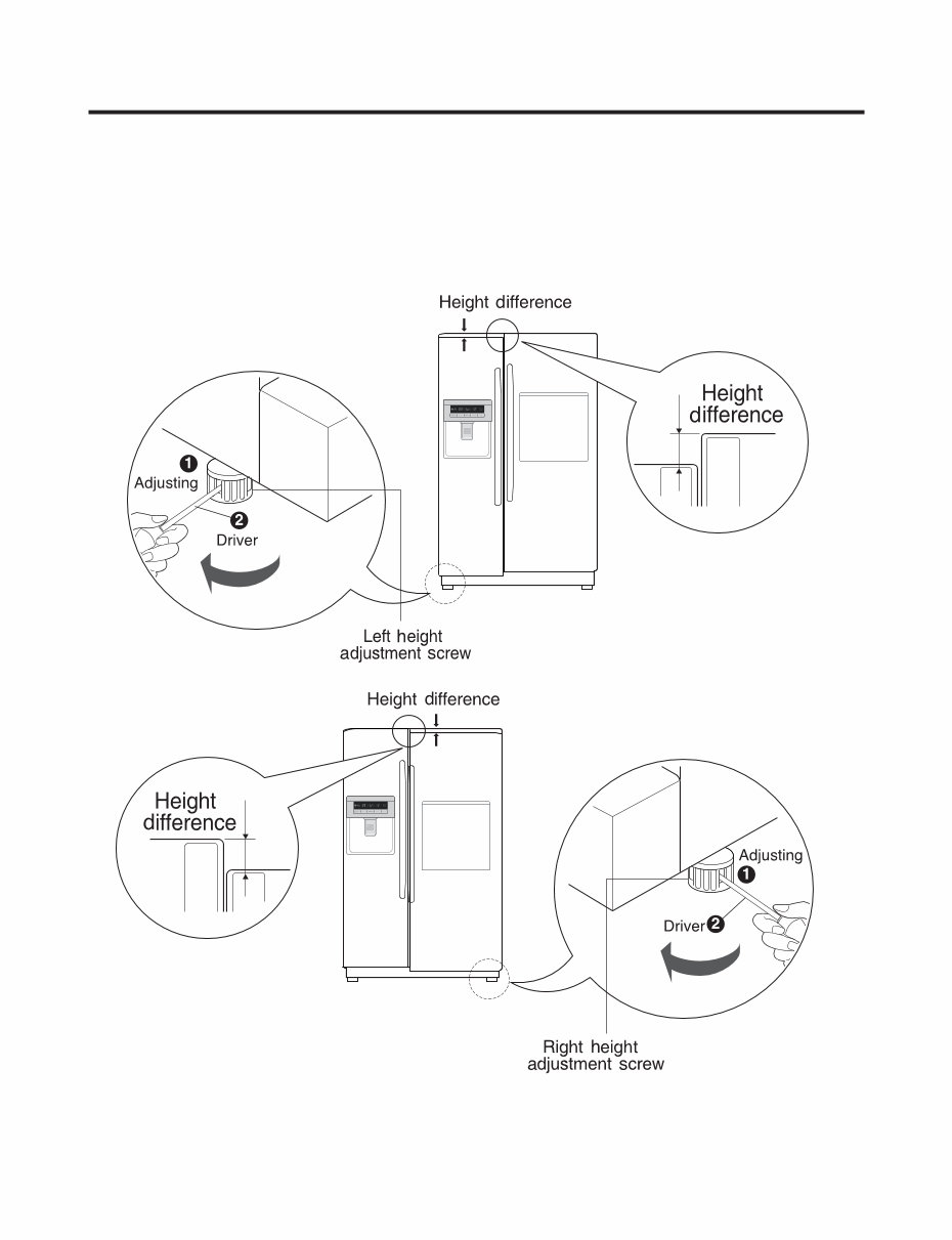
1. How to Adjust Door Height of Refrigerator ■ Make the refrigerator level first. (If the refrigerator is not installed on the flat floor, the height of freezer and refrigerator door may not be the same.) 1. If the height of freezer door is lower than that of refrigerator compartment : 2. If the height of freezer door is higher than that of refrigerator compartment : Insert a driver B into the groove A of adjusting screw and rotate driver in arrow direction (clockwise) until the refrigerator becomes horizontal. Insert a driver B into the groove A of adjusting screw and rotate driver in arrow direction (clockwise) until the refrigerator becomes horizontal. HOW TO INSTALL REFRIGERATOR - 8 -
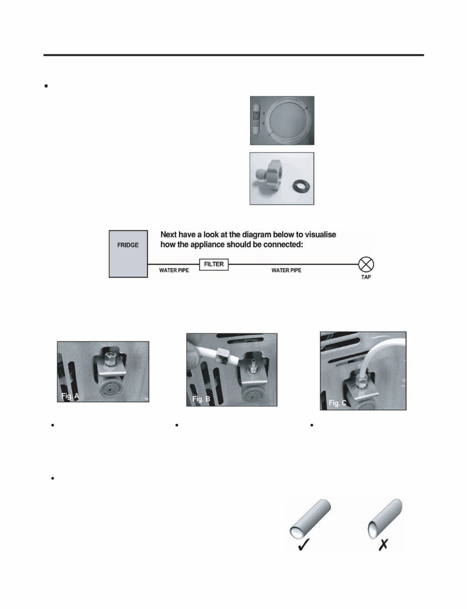
2. Connection to Main Water Supply Before Installation 1. The icemaker requires the water pressure of 1.5 - 8.5kgf/cm 2 . (It is acceptable if city water fills a cup of 180cc with water for 3 seconds) 2. Install booster pump where the city water pressure is below 1.5kgf/cm 2 for normal operation of water and ice dispenser. 3. The total length of water pipe shall be less than 12m. Do not bend the pipe at right angle. If the length is more than 12m, there will be troubles on water supply due to water pressure drop. 4. Please install water pipe where there is no heat around. 2-1. Check all correct items (In case of External Filter Models). 2-2. Connection to the Appliance (In case of External or Internal Filter Models). HOW TO INSTALL REFRIGERATOR 1 x Connector type Water Filter 2 x Clips 1 x 8mm Water Pipe Plastic Pipe Connector Rubber Washer At the back of the appliance you will see the water inlet valve. (See Fig. A) You now need to cut the water pipe to the right lenght for connection of the water filter. It is suggested that approximately 1.5mm of pipe is used - this should allow the filter to be located in an accessible position (for periodic replacement) and also allow some slack in the pipe behind the machine so that it con be pulled out for cleaning or servicing purposes. Unscrew the metal thearded collar and place it over one end of the water pipe. (See Fig. B) Firmly push the water pipe onto the water inlet valve and tighten up the metal collar. (See Fig. C) You must also ensure that the cut is square and not at any sort of angle as this could cause a leak. - 9 -
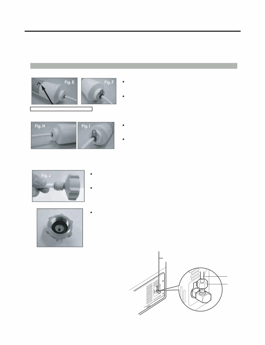
2-3. Connection of Water Filter (In case of External Filter Models). 2-4. Connection to the Water Tap (In case of External and Internal Filter Models). 2-5. Water Supply 1) After the installation of feed water, plug the refrigerator Now you have cut the pipe from the back of the appliance to lenght. It needs to be attached to the water filter. The filter is marked with with the direction of the water flow (i.e. from tap to fridge). Just insert tube into the end of the filter that the flow arrow points until the tube stop. (See Fig. E) After inserting tube, put together the clip strongly. The clip fix the tube. (See Fig. F) Remember however that the connection is being done from the refrigerator to the tap (i.e. the reverse of the water flow when in use). to the earthered wall outlet, press the water dispenser button for 2 - 3 minutes, and confirm that the water comes out. 2) Check leakage at connecting part, then arrange water tube and locate the refrigerator at its regular place if there is no leaking. HOW TO INSTALL REFRIGERATOR Note the direction markings on the filter! Repeat on the other end of the filter using the remainder of the water pipe. (See Fig. H) Cut the pipe that is connected to the water filter to the correct lenght. Again, make sure that the cut is nice and square to avoid leaks. Push the pipe into the smaller hole of the connector supplied in the plumbing adapter kit. The pipe should be held firm. (See Fig. J) Place the rubber washer inside the threaded tap connector and screw onto water tap. CAUTION: feed pipe should be connected to cold water line. If it’s connected to hot water line, trouble may occur. If you have connector type filter, put together the clip strongly. The clip fix the tube. (See Fig. I) Water Tube Water Tube Nut - 10 -
Are you experiencing issues with your LG refrigerator? Why spend money on replacements or repairs when you can easily fix it yourself with the right service documentation?
This service and repair manual, used by Official Certified LG Technicians, will assist you in troubleshooting and repairing your fridge. It is a valuable resource for both professional mechanics and DIY enthusiasts.
With this manual, you will gain insights into safety precautions, servicing precautions, specifications, parts identification, installation procedures, disassembly instructions, circuit diagrams, troubleshooting, ice maker and dispenser working principles and repair, cooling cycle heavy repair, micom function & circuit, code errors, and exploded view.
Featuring detailed illustrations and step-by-step instructions, this manual is designed to help you service and repair your device effectively. It is available in a high-resolution format, ensuring excellent print quality from any printer and computer.
Upon payment, you will have instant access to the manual, eliminating the need for shipping and allowing you to commence repairs immediately. The manual is in English and compatible with both Windows and MAC platforms.
If you are unable to find a specific service manual, feel free to contact us with your request. With the largest and most comprehensive service manual database, we are well-equipped to assist you.