

LG GR P227 P257 L227 L257 C227 C257 B227 B257Service Manual
What's Included?
Fast Download Speeds
Online & Offline Access
Access PDF Contents & Bookmarks
Full Search Facility
Print one or all pages of your manual
REFRIGERATOR
SERVICE MANUAL
CAUTION
PLEASE READ CAREFULLY THE SAFETY PRECAUTIONS OF THIS BOOK
BEFORE CHECKING OR OPERATING THE REFRIGERATOR.
http://biz.lgservice.com
Ref No :
GR-P227
GR-P257
Ref No :
GR-L227
GR-L257
Ref No :
GR-C227
GR-C257
Ref No :
GR-B227
GR-B257

- 2 -
CONTENTS
WARNINGS AND PRECAUTIONS FOR SAFETY ................................................................................................................. 3
SPECIFICATIONS ................................................................................................................................................................... 4
PARTS IDENTIFICATION ....................................................................................................................................................... 5
HOW TO INSTALL THE REFRIGERATOR ............................................................................................................................ 7
HOW TO ADJUST DOOR HEIGHT OF THE REFRIGERATOR .......................................................................................... 7
HOW TO INSTALL WATER PIPE......................................................................................................................................... 8
HOW TO CONTROL THE AMOUNT OF WATER SUPPLIED TO THE ICEMAKER ......................................................... 12
MICOM FUNCTION ............................................................................................................................................................... 14
EXPLATION FOR MICOM CIRCUIT ..................................................................................................................................... 23
EXPLANATION FOR PWB CIRCUIT ................................................................................................................................. 23
COMPENSATION CIRCUIT FOR WEAK-COLD, OVER-COLD AT FREEZING ROOM ....................................................40
PWB PARTS DRAWING AND LIST ................................................................................................................................... 41
ICE MAKER AND DISPENSER WORKING PRINCIPLES AND REPAIR ........................................................................... 44
WORKING PRINCIPLES ................................................................................................................................................... 44
FUNCTION OF ICE MAKER .............................................................................................................................................. 45
ICE MAKER TROUBLESHOOTING .................................................................................................................................. 48
CIRCUIT ................................................................................................................................................................................ 49
TROUBLE DIAGNOSIS ........................................................................................................................................................ 50
TROUBLE SHOOTING ...................................................................................................................................................... 50
FAULTS .............................................................................................................................................................................. 60
COOLING CYCLE HEAVY REPAIR .................................................................................................................................. 77
HOW TO DEAL WITH CLAIMS .......................................................................................................................................... 84
HOW TO DISASSEMBLE AND ASSEMBLE ....................................................................................................................... 89
DOOR ................................................................................................................................................................................. 89
SHROUD, GRILLE FAN ..................................................................................................................................................... 90
ICEMAKER ......................................................................................................................................................................... 90
WATER VALVE DISASSEMBLY METHOD ....................................................................................................................... 91
FAN and FAN MOTOR DISASSEMBLY METHOD ............................................................................................................ 91
DISPENSER ....................................................................................................................................................................... 92
HOME BAR ........................................................................................................................................................................ 94
EXPLODED VIEW ................................................................................................................................................................. 95
REPLACEMENT PARTS LIST ........................................................................................................................................... 103

- 3 -
WARNINGS AND PRECAUTIONS FOR SAFETY
Please observe the following safety precautions in order to
use safely and correctly the refrigerator and to prevent
accident and danger during repair.
1. Be care of an electric shock. Disconnect power cord
from wall outlet and wait for more than three minutes
before replacing PWB parts. Shut off the power
whenever replacing and repairing electric components.
2. When connecting power cord, please wait for more than
five minutes after power cord was disconnected from the
wall outlet.
3. Please check if the power plug is pressed down by the
refrigerator against the wall. If the power plug was
damaged, it may cause fire or electric shock.
4. If the wall outlet is over loaded, it may cause fire. Please
use its own individual electrical outlet for the refrigerator.
5. Please make sure the outlet is properly earthed,
particularly in wet or damp area.
6. Use standard electrical components when replacing
them.
7. Make sure the hook is correctly engaged.
Remove dust and foreign materials from the housing
and connecting parts.
8. Do not fray, damage, machine, heavily bend, pull out, or
twist the power cord.
9. Please check the evidence of moisture intrusion in the
electrical components. Replace the parts or mask it with
insulation tapes if moisture intrusion was confirmed.
10. Do not touch the icemaker with hands or tools to confirm
the operation of geared motor.
11. Do not let the customers repair, disassemble, and
reconstruct the refrigerator for themselves. It may cause
accident, electric shock, or fire.
12. Do not store flammable materials such as ether,
benzene, alcohol, chemicals, gas, or medicine in the
refrigerator.
13. Do not put flower vase, cup, cosmetics, chemicals, etc.,
or container with full of water on the top of the
refrigerator.
14. Do not put glass bottles with full of water into the
freezer. The contents shall freeze and break the glass
bottles.
15. When you scrap the refrigerator, please disconnect the
door gasket first and scrap it where children are not
accessible.
- 4 -
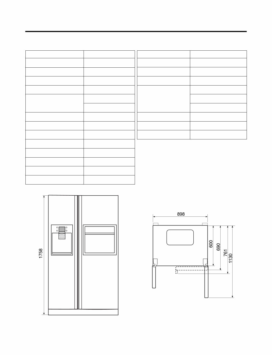
SPECIFICATIONS
1. Ref No. : GR-P227/L227
ITEMS
DIMENSIONS (mm)
NET WEIGHT (kg)
COOLING SYSTEM
TEMPERATURE CONTROL
DEFROSTING SYSTEM
INSULATION
COMPRESSOR
EVAPORATOR
CONDENSER
REFRIGERANT
LUBRICATING OIL
DRIER
CAPILLARY TUBE
898(W)X761(D)X1758(H)
162/159
Fan Cooling
Micom Control
Full Automatic
Heater Defrost
Cyclo-Pentane
P.T.C. Starting Type
Fin Tube Type
Wire Condenser
R134a (180g)
FREOL@10G (310 cc)
ID 0.83
MOLECULAR SIEVE XH-7
SPECIFICATIONS ITEMS
FIRST DEFROST
DEFROST CYCLE
DEFROSTING DEVICE
ANTI SWEAT HEATER
ANTI-FREEZING HEATER
FREEZER LAMP
REFRIGERATOR LAMP
4 - 5 Hours
13 - 15 Hours
Heater, Sheath
Dispenser Duct Door Heater
Dispenser Heater
Home Bar Heater
Damper Heater
40W (1 EA)
40W (1 EA) or 30W (1 EA)
SPECIFICATIONS
<Front View> <Plane View>
- 5 -
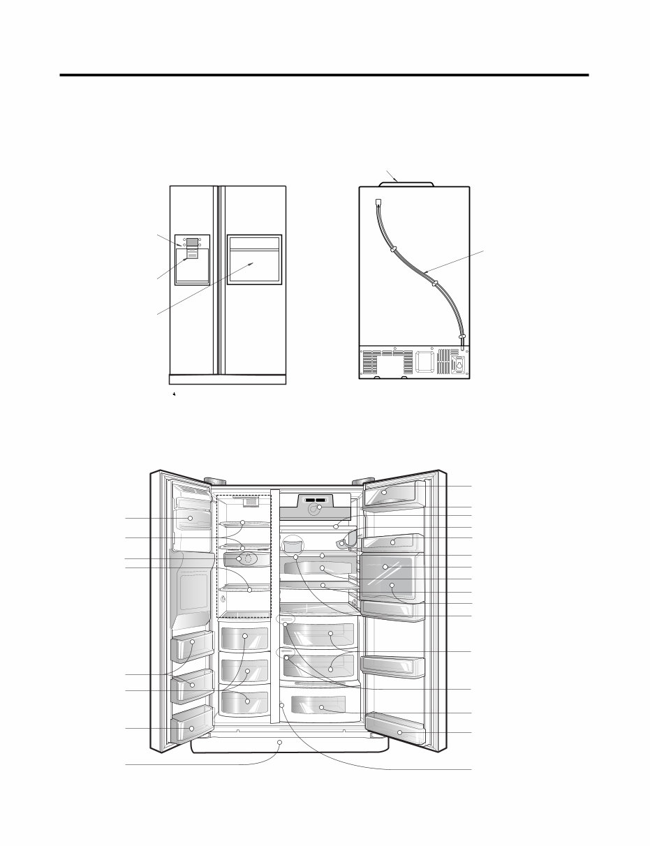
PARTS IDENTIFICATION
1. Ref No. : GR-P227/L227(INTERNAL FILTER), GR-P257/L257
Dispenser Cover
Assembly
Ice & Water
Dispenser Button
Cover PWB
Water Tube
Home Bar
L227 : Non Home bar
Automatic
Icemaker
Shelf or Drawer
Lamp
Shelf or Drawer
Milk product corner
Can Server (Optional)
Refreshment center (Optional)
Shelf
Shelf (Folding or Normal)
Egg Box
Miracle Zone (Optional)
Fresh compartment
(Optional)
Conversion switch
(Meats/Vegetables)
(Optional)
Wine holder (Plastic or wire)
Door Rack
Snack drawer (Optional)
Humidity switch
Vegetable Drawer
(1 or 2)
Door Rack
Door rack
Drawer (2 or 3)
Door rack
Lower cover
Freezer
Compartment
Refrigerator
Compartment
Shelf
Lamp
- 6 -
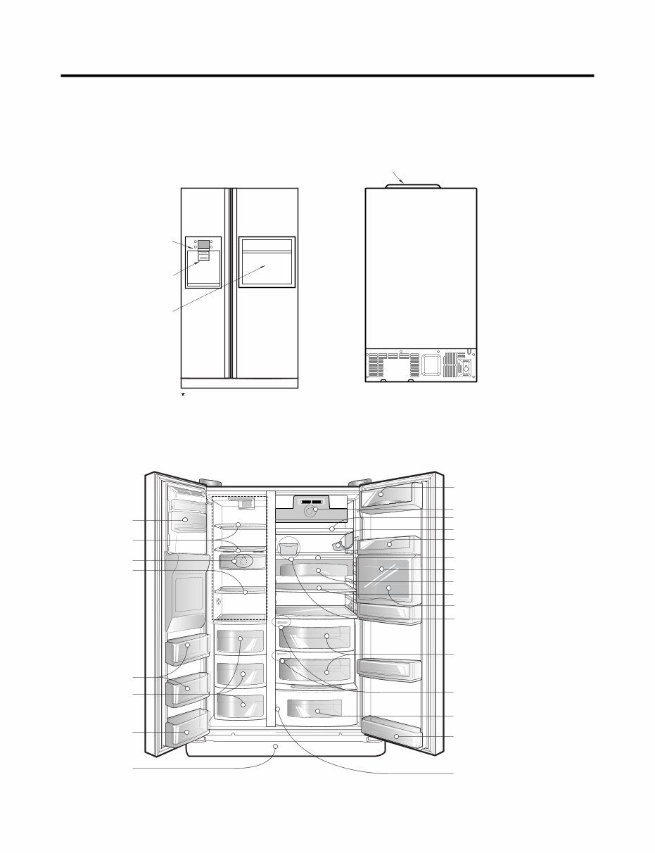
PARTS IDENTIFICATION
2. Ref No. : GR-P227/L227(EXTERNAL FILTER), GR-P257/L257
Dispenser Cover
Assembly
Ice & Water
Dispenser Button
Home Bar
L227 : Non Home bar
Cover PWB
Automatic
Icemaker
Shelf
Lamp
Shelf
Door rack
Drawer (2 or 3)
Door rack
Lower cover
Milk product corner
Can Server (Optional)
Refreshment center (Optional)
Shelf
Shelf (Folding or Normal)
Egg Box
Miracle Zone (Optional)
Fresh compartment
(Optional)
Conversion switch
(Meats/Vegetables)
(Optional)
Wine holder (Plastic or wire)
Door Rack
Snack drawer (Optional)
Humidity switch
Vegetable Drawer
(1 or 2)
Door Rack
Shelf
Lamp
Freezer
Compartment
Refrigerator
Compartment
- 7 -
HOW TO INSTALL REFRIGERATOR
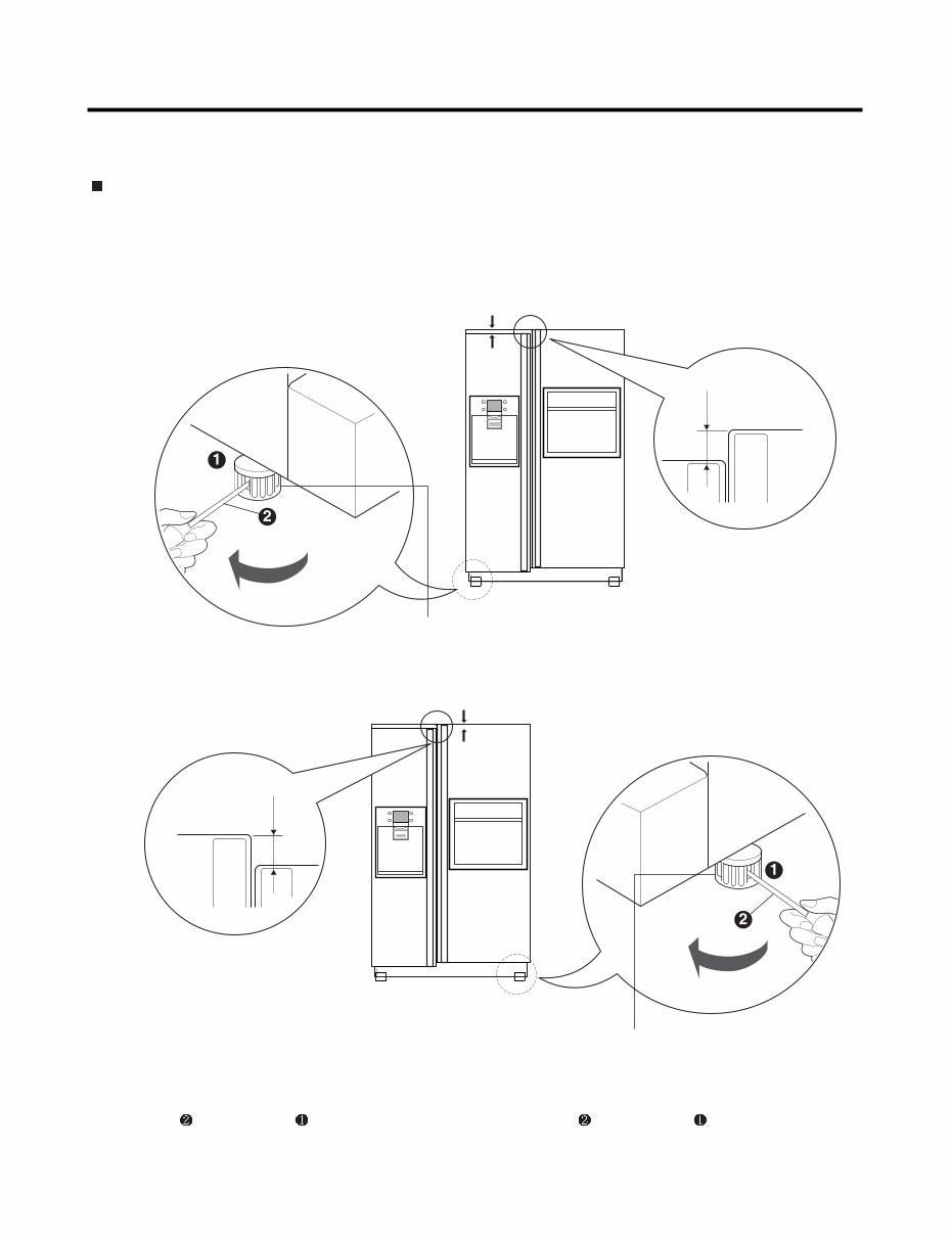
1. How to Adjust Door Height of Refrigerator
Make the refrigerator level first. (If the refrigerator is not installed on the flat floor, the height of freezer and refrigerator
door may not be the same.)
1. If the height of freezer door is lower than that of
refrigerator compartment :
Insert a driver into the groove of adjusting screw
and rotate driver in arrow direction (clockwise) until the
refrigerator becomes horizontal.
Insert a driver into the groove of adjusting screw
and rotate driver in arrow direction (clockwise) until the
refrigerator becomes horizontal.
2. If the height of freezer door is higher than that of
refrigerator compartment :
Height difference
Height
difference
Height
difference
Left helght
adjustment screw
Right helght
adjustment screw
Height difference
Adjusting
Driver
Driver
Adjusting
- 8 -
HOW TO INSTALL REFRIGERATOR
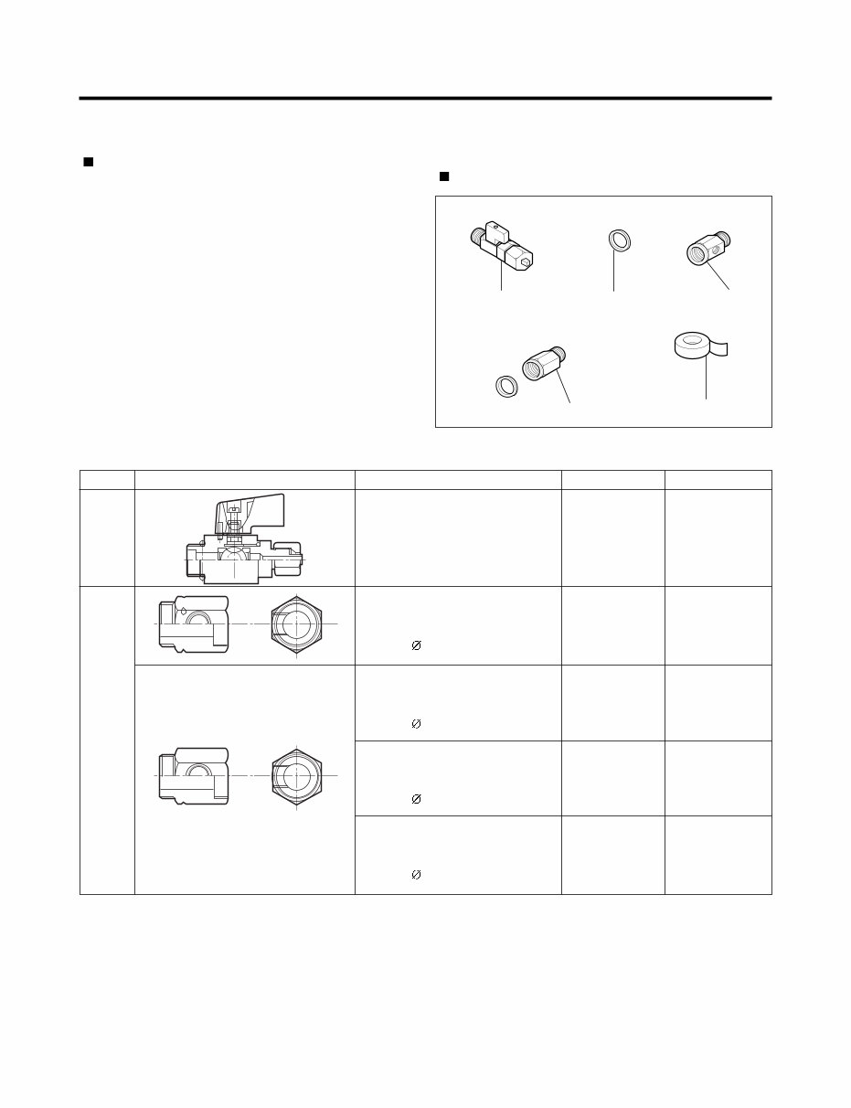
2. How to Install Water Pipe
Before Installation
Please confirm the following installation parts.
1. The icemaker requires the water pressure of 1.5 -
8.5kgf/cm
2
. (It is acceptable if city water fills a cup of
180cc with water for 3 seconds)
2. Install booster pump where the city water pressure is
below 1.5kgf/cm
2
for normal operation of water and ice
dispenser.
3. The total length of water pipe shall be less than 12m. Do
not bend the pipe at right angle. If the length is more
than 12m, there will be troubles on water supply due to
water pressure drop.
4. Please install water pipe where there is no heat around.
2-1. When connecting directly to the water
tap.
Valve Feed
Connector, Pipe
Tape, Teflon
Rubber, Packing Connector, Pipe
Class.
Conve-
rtible
Water
Valve
Water
Conn-
ector
Valve Feed
Connector, (MECH) Pipe
Conversion Connector(3/4")
Balance Conector(3/4")
Packing( 24x3t)
4932JA3003B
Conversion Connector(W25)
Balance Conectoor(W25)
Packing( 23x3t)
Connector, (MECH) Pipe
Conversion Connector(W28)
Balance Conector(W28)
Packing( 26x3t)
Connector, (MECH) Pipe
Conversion Connector(1/2")
Balance Conector(1/2")
Packing( 19x3t)
5221JA3001A
4932JA3003A
6631JA3004A
6631JA3004B
3920JA3001B
6631JA3004C
6631JA3004D
3920JA3001A
4932JA3003C
6631JA3004E
6631JA3004F
3920JA3001C
4932JA3003D
6631JA3004G
6631JA3004H
3920JA3001D
Common Use
No Holes
No Holes
No Holes
No Holes
Shape and Spec.
Connector, (MECH) Pipe
Nomenclature P/No Remarks
- 9 -
HOW TO INSTALL REFRIGERATOR
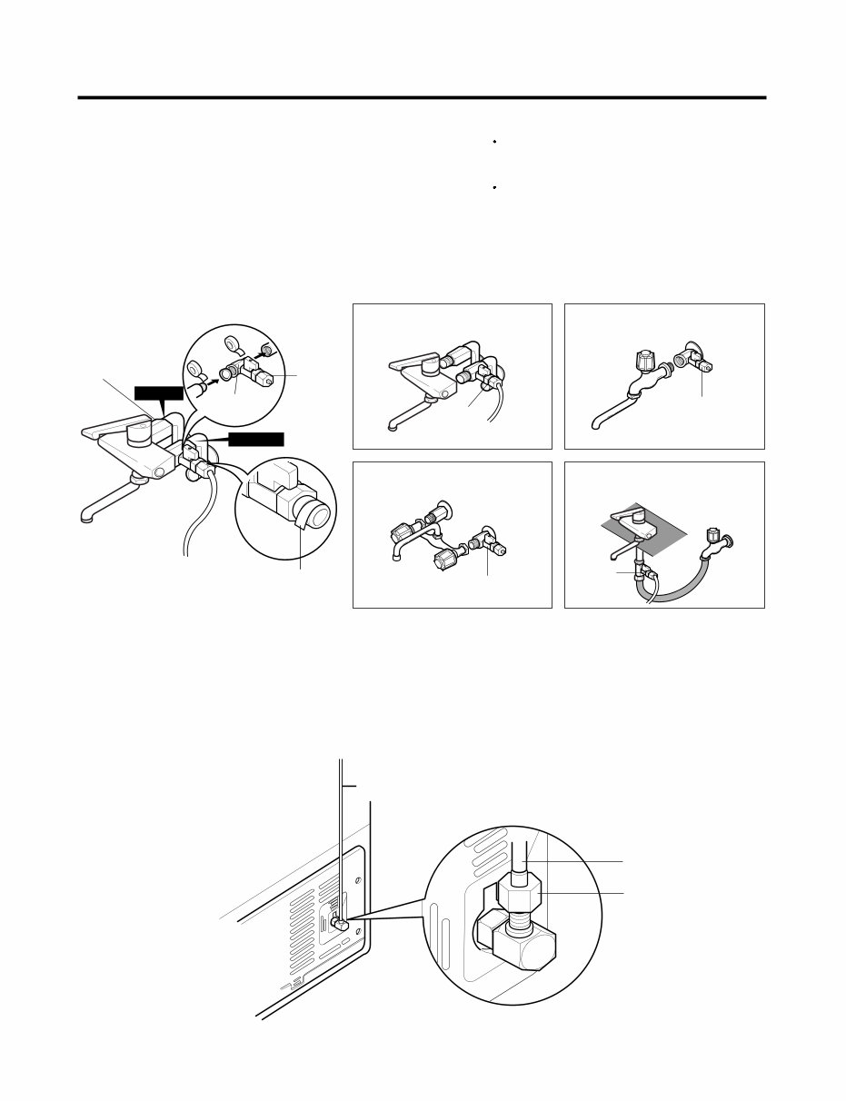
1. Connection of Pipe Connector A and B. Caution : Feed pipe should be connected to cold water
line. If it is connected to hot water line, trouble
may occur.
Please check rubber packing when
connecting feed pipe.
1) Turn off main valve of water pipe.
2) Disconnect water tap from piping by loosening nuts.
3) Connect pipe connector A and B to piping after sealing
the pipe connector with sealing tapes.
4) Connect feed valve to pipe connector A.
5) If there is only one tap water pipe, connect pipe
connector A only and install feed pipe.
Pipe Connector B
Hot Water
Cold Water
Pipe Connector A
Feed
Valve
Feed
Valve
Feed
Valve
Feed
Valve
Feed
Valve
How to wind
Sealing Tapes.
Single Lever Type Faucet
(general)
General Type
Single Lever Type Faucet (one
hole, tech type and hand spray)
Two Hands Type Faucet
2. Water Supply
1) After the installation of feed water, plug the refrigerator to
the earthered wall outlet, press the water dispenser
button for 2 - 3 minutes, and confirm that the water
comes out.
2) Check leakage at connecting part, then arrange water
tube and locate the refrigerator at its regular place if
there is no leaking.
Water Tube
Nut
Water Tube
- 10 -
HOW TO INSTALL REFRIGERATOR
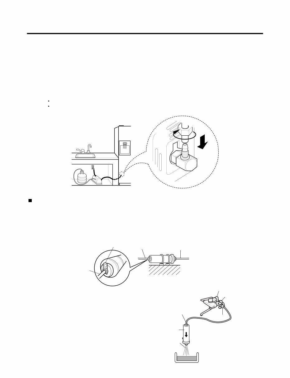
3. When customer uses bottled water.
Caution : If feed tube is more than 4m, less water will come out due to pressure drops.
Use standard feed tube to prevent leaking.
1. The pump system should not be on the floor (it may cause noise and vibration). Securely fasten the inlet and outlet nuts
of pump.
2. If there is any leakage after installation, cut the water tube at right angle and reassemble.
3. When put the water tube end into the bottle, leave a clearance between bottle bottom and water tube end.
4 Check water coming out and any leakage.
* If customer wants to use bottled water, extra pump should be installed as shown below.
Outternal Filter
1. Filter Fixation
1) Connect feed tube to the filter outlet and water valve connecting tube.
2) Fix the filter at proper place around the sink where it is easy to replace the filter and to receive the cleaning water.
Please consider the length of tube shall be less than 8m when locating filter.
2. Filter Cleaning
1) Connect feed tube to the inlet of feed valve and filter.
2) Clean the main valve and feed valve with water for at least
one minute until clean water comes out.
Water Tube
Feed Valve
Water
Outlet
Inlet
Connector Type
Clip
Filter
Filter Inlet
Cold Water
Hot Water
You're Reading a Preview
What's Included?
Fast Download Speeds
Online & Offline Access
Access PDF Contents & Bookmarks
Full Search Facility
Print one or all pages of your manual
$31.99
Viewed 51 Times Today


Secure transaction
What's Included?
Fast Download Speeds
Online & Offline Access
Access PDF Contents & Bookmarks
Full Search Facility
Print one or all pages of your manual
$31.99
This service manual is available in English and comes in PDF format. It is designed to provide technical information for the maintenance and repair of LG GR P227, P257, L227, L257, C227, C257, B227, and B257 models. Whether you are a professional mechanic or a DIY enthusiast, this manual is a valuable resource for troubleshooting and servicing these specific LG models.


