CAUTIO N PLEASE READ CAREFULLY THE SAFETY PRECAUTIONS OF THIS BOO K BEFORE CHECKING OR OPERATING THE REFRIGERATO R . REFRIGERATOR SERVICE MANUA L http://biz.lgservice.com M O D E L: GC-L197NFS COLOR:Titanium
WARNINGS AND PRECAUTIONS FOR SAFETY ................................................................................................................ 3 SPECIFICATIONS................................................................................................................................................................... 4 PARTS IDENTIFICATION ........................................................................................................................................................5 HOW TO INSTALL THE REFRIGERATOR .......................................................................................................................... 10 HOW TO ADJUST DOOR HEIGHT OF THE REFRIGERATOR ........................................................................................ 10 HOW TO INSTALL WATER PIPE........................................................................................................................................11 HOW TO CONTROL THE AMOUNT OF WATER SUPPLIED TO THE ICEMAKER ......................................................... 15 MICOM FUNCTION .............................................................................................................................................................. 17 EXPLATION FOR MICOM CIRCUIT..................................................................................................................................... 23 EXPLANATION FOR PWB CIRCUIT ................................................................................................................................. 23 COMPENSATION CIRCUIT FOR WEAK-COLD, OVER-COLD AT FREEZING ROOM.................................................... 30 PWB PARTS DRAWING AND LIST ................................................................................................................................... 35 PWB CIRCUIT DIAGRAM .................................................................................................................................................. 41 ICE MAKER AND DISPENSER WORKING PRINCIPLES AND REPAIR ........................................................................... 45 WORKING PRINCIPLES.................................................................................................................................................... 45 FUNCTION OF ICE MAKER .............................................................................................................................................. 46 ICE MAKER TROUBLESHOOTING...................................................................................................................................49 ICE MAKER CIRCUITS ...................................................................................................................................................... 50 CIRCUIT ................................................................................................................................................................................ 51 TROUBLE DIAGNOSIS ........................................................................................................................................................ 53 TROUBLE SHOOTING ...................................................................................................................................................... 53 FAULTS ............................................................................................................................................................................ 63 COOLING CYCLE HEAVY REPAIR ................................................................................................................................. 80 HOW TO DEAL WITH CLAIMS ........................................................................................................................................ 87 HOW TO DISASSEMBLE AND ASSEMBLE ..................................................................................................................... 92 DOOR ............................................................................................................................................................................... 92 HANDLE ........................................................................................................................................................................... 93 SHROUD, GRILLE FAN ................................................................................................................................................... 93 ICEMAKER ....................................................................................................................................................................... 93 DISPENSER ..................................................................................................................................................................... 94 HOME BAR ...................................................................................................................................................................... 90 EXPLODED VIEW .............................................................................................................................................................. 94 CONTENTS - 2 -
Please observe the following safety precautions in order to use safely and correctly the refrigerator and to prevent accident and danger during repair. 1. Be care of an electric shock. Disconnect power cord from wall outlet and wait for more than three minutes before replacing PWB parts. Shut off the power whenever replacing and repairing electric components. 2. When connecting power cord, please wait for more than five minutes after power cord was disconnected from the wall outlet. 3. Please check if the power plug is pressed down by the refrigerator against the wall. If the power plug was damaged, it may cause fire or electric shock. 4. If the wall outlet is over loaded, it may cause fire. Please use its own individual electrical outlet for the refrigerator. 5. Please make sure the outlet is properly earthed, particularly in wet or damp area. 6. Use standard electrical components when replacing them. 7. Make sure the hook is correctly engaged. Remove dust and foreign materials from the housing and connecting parts. 8. Do not fray, damage, machine, heavily bend, pull out, or twist the power cord. 9. Please check the evidence of moisture intrusion in the electrical components. Replace the parts or mask it with insulation tapes if moisture intrusion was confirmed. 10. Do not touch the icemaker with hands or tools to confirm the operation of geared motor. 11. Do not let the customers repair, disassemble, and reconstruct the refrigerator for themselves. It may cause accident, electric shock, or fire. 12. Do not store flammable materials such as ether, benzene, alcohol, chemicals, gas, or medicine in the refrigerator. 13. Do not put flower vase, cup, cosmetics, chemicals, etc., or container with full of water on the top of the refrigerator. 14. Do not put glass bottles with full of water into the freezer. The contents shall freeze and break the glass bottles. 15. When you scrap the refrigerator, please disconnect the door gasket first and scrap it where children are not accessible. WARNINGS AND PRECAUTIONS FOR SAFETY - 3 -
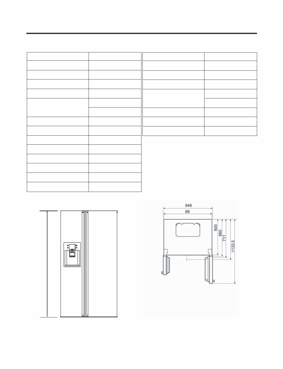
SPECIFICATIONS - 4 - ITEMS SPECIFICATIONS DIMENSIONS (mm) 894(W)X725(D)X1753(H) NET WEIGHT (kg) 122 COOLING SYSTEM Fan Cooling TEMPERATURE CONTROL Micom Control DEFROSTING SYSTEM Full Automatic Heater Defrost INSULATION Cyclo-Pentane COMPRESSOR P.T.C. Starting Type EVAPORATOR Fin Tube Type CONDENSER Wire Condenser REFRIGERANT R134a (180g) LUBRICATING OIL FREOL @10G (310 cc) DRIER ID 0.83 CAPILLARY TUBE MOLECULAR SIEVE XH-7 1. Ref No. :GC-L207W ITEMS SPECIFICATIONS FIRST DEFROST 4 - 5 Hours DEFROST CYCLE 13 - 15 Hours DEFROSTING DEVICE Heater, Sheath ANTI SWEAT HEATER Dispenser Duct Door Heater Dispenser Heater ANTI-FREEZING HEATER Damper Heater FREEZER LAMP 40W (1 EA) REFRIGERATOR LAMP 40W (1 EA) 5 2 7 3 5 7 1 4
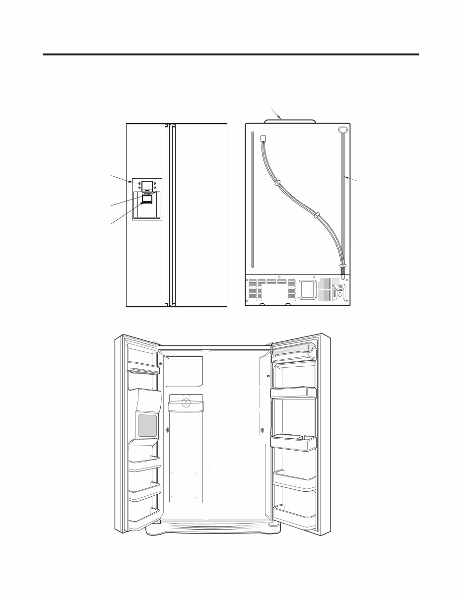
PARTS IDENTIFICATION - 5 - Cover PWB Water Tube Frame Display Dispenser Lamp Ice & Water Dispenser Button 1. Ref No. : GC-L207W
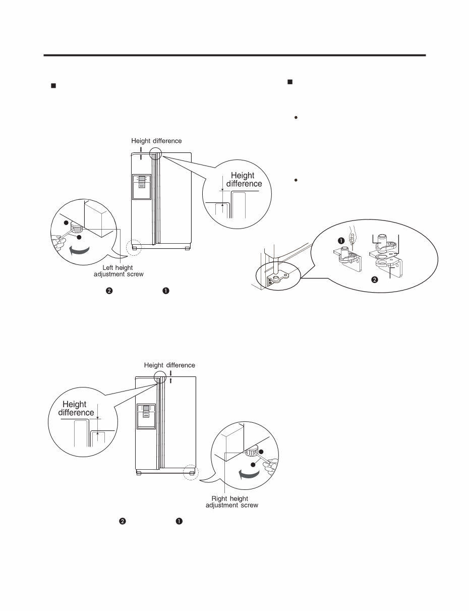
1. How to Adjust Door Height of Refrigerator Make the refrigerator level first. (If the refrigerator is not installed on the flat floor, the height of freezer and refrigerator door may not be the same. 1. If the height of freezer door is lower than that of refrigerator compartment : 2. If the height of freezer door is higher than that of refrigerator compartment : Insert a driver into the groove of adjusting screw and rotate driver in arrow direction (clockwise) until the refrigerator becomes horizontal. Insert a driver into the groove of adjusting screw and rotate driver in arrow direction (clockwise) until the refrigerator becomes horizontal. HOW TO INSTALL REFRIGER ATOR - 6 - 1 1 2 2 Adjusting Adjusting Driver Driver Even if the height can not be aligned by using the height adjustment screw,insert the transparent sheet supplied with the product. Bottom bracket Transparent sheet Bottom hinge Separate the door with the lower height, use the (+) type screwdriver to unscrew the screw at the botton hinge as shown at figure , insert the transparent sheet between the bottom hinge and the bottom bracket,and then fix it with the screw as shown at figure . Insert more transparent sheets enough to align the height.(4 sheets are supplied in total.)
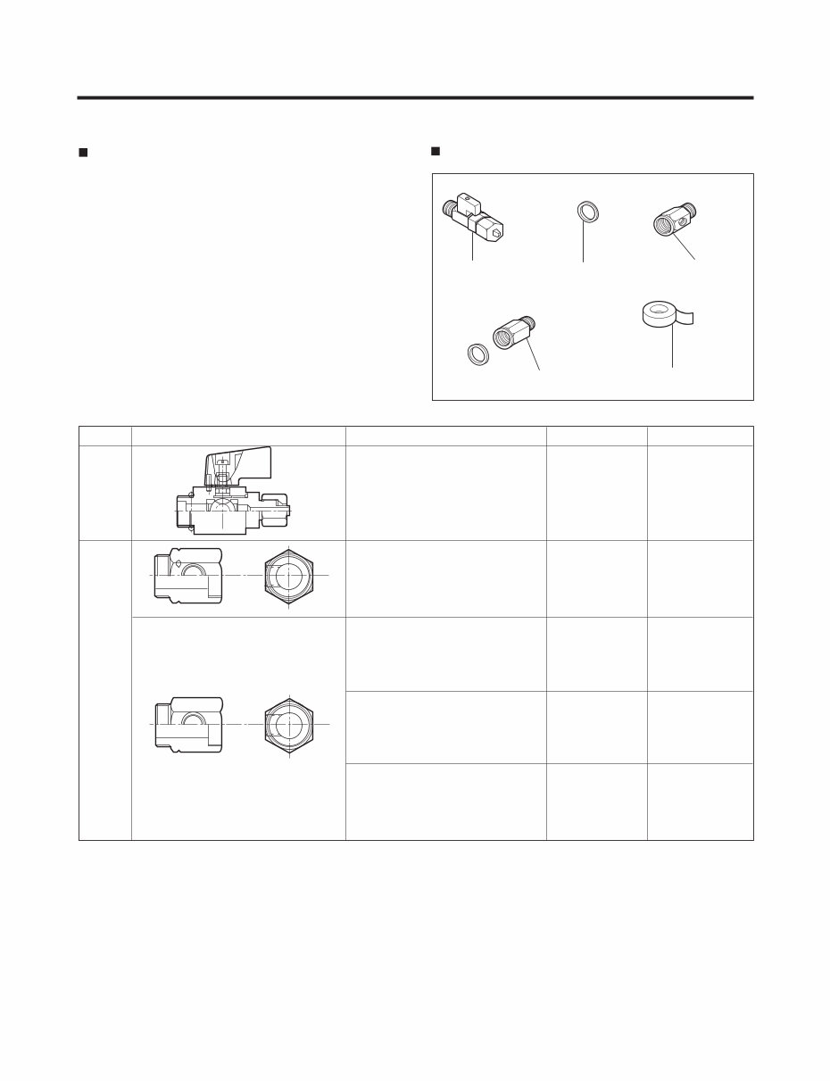
2. How to Install Water Pipe Before Installation 1. The icemaker requires the water pressure of 1.5 - 5.1kgf/cm 2 . (It is acceptable if city water fills a cup of 180cc with water for 3 seconds).Automatic ice maker operation needs water pressure of 147-500kpa. 2. Install booster pump where the city water pressure is below 1.5kgf/cm 2 for normal operation of water and ice dispenser. 3. The total length of water pipe shall be less than 12m. Do not bend the pipe at right angle. If the length is more than 12m, there will be troubles on water supply due to water pressure drop. 4. Please install water pipe where there is no heat around. 2-1. When connecting directly to the water tap. Please confirm the following installation parts. HOW TO INSTALL REFRIGERATOR -7 - Class. Shape and Spec. Nomenclature P/No Remarks e s U n o m m o C A 1 0 0 3 A J 1 2 2 5 d e e F e v l a V Connector, (MECH) Pipe 4932JA3003A Conversion Connector(3/4") 6631JA3004A No Holes Balance Conector(3/4") 6631JA3004B Packing(ø24x3t) 3920JA3001B Connector, (MECH) Pipe 4932JA3003B Conversion Connector(W25) 6631JA3004C No Holes Balance Conectoor(W25) 6631JA3004D Packing(ø23x3t) 3920JA3001A Connector, (MECH) Pipe 4932JA3003C Conversion Connector(W28) 6631JA3004E No Holes Balance Conector(W28) 6631JA3004F Packing(ø26x3t) 3920JA3001C Connector, (MECH) Pipe 4932JA3003D Conversion Connector(1/2") 6631JA3004G No Holes Balance Conector(1/2") 6631JA3004H Packing(ø19x3t) 3920JA3001D Conve- rtible Water Valve Water Conn- ector Valve Feed Rubber, Packing Connector, Pipe Tape, Teflon Connector, Pipe
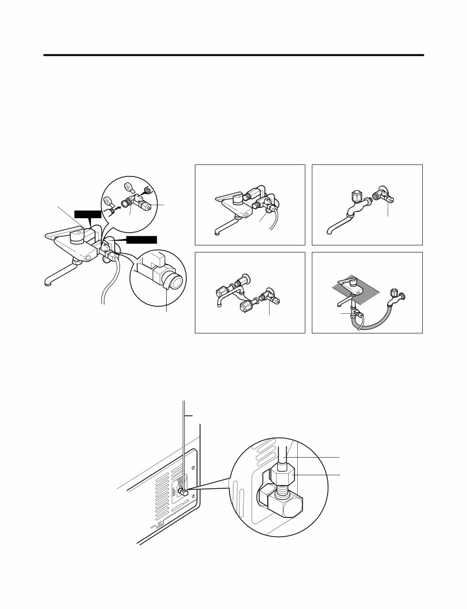
1. Connection of Pipe Connector A and B. 1) Turn off main valve of water pipe. 2) Disconnect water tap from piping by loosening nuts. 3) Connect pipe connector A and B to piping after sealing the pipe connector with sealing tapes. 4) Connect feed valve to pipe connector A. 5) If there is only one tap water pipe, connect pipe connector A only and install feed pipe. 2. Water Supply 1) After the installation of feed water, plug the refrigerator to the earthered wall outlet, press the water dispenser button for 2 - 3 minutes, and confirm that the water comes out. Caution : • Feed pipe should be connected to cold water line. If it is connected to hot water line, trouble may occur. • Please check rubber packing when connecting feed pipe. 2) Check leakage at connecting part, then arrange water tube and locate the refrigerator at its regular place if there is no leaking. HOW TO INSTALL REFRIGERATOR - 8 - Single Lever Type Faucet (general) Feed Valve General Type Feed Valve Two Hands Type Faucet Single Lever Type Faucet (one hole, tech type and hand spray) Feed Valve Feed Valve Pipe Connector B Hot Water Pipe Connector A Feed Valve Cold Water How to wind Sealing Tapes. Water Tube Water Tube Nut
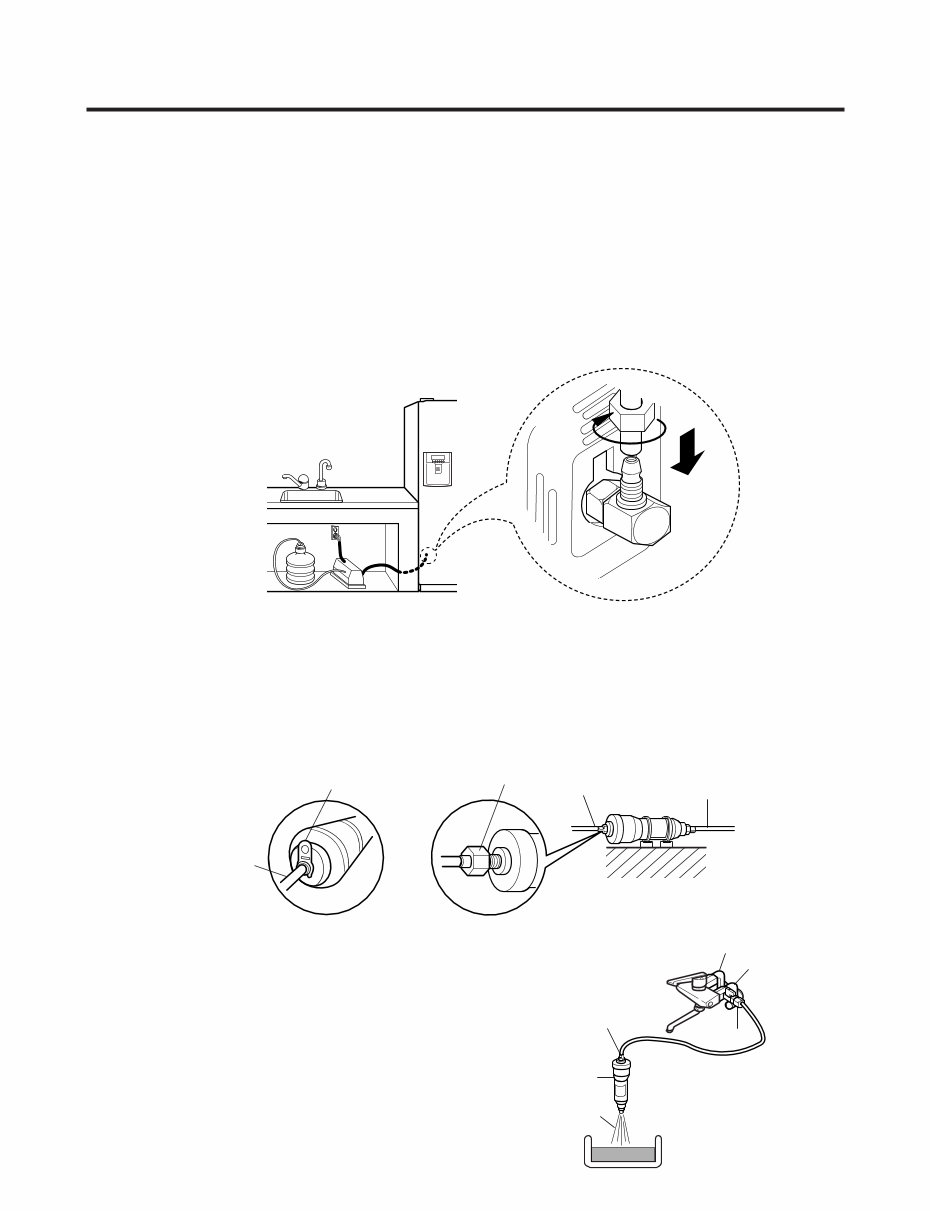
3. When customer uses bottled water. *If customer wants to use bottled water, extra pump should be installed as shown below. 1. The pump system should not be on the floor (it may cause noise and vibration). Securely fasten the inlet and outlet nuts of pump. 2. If there is any leakage after installation, cut the water tube at right angle and reassemble. 3. When put the water tube end into the bottle, leave a clearance between bottle bottom and water tube end. 4 Check water coming out and any leakage. Caution : • If feed tube is more than 4m, less water will come out due to pressure drops. • Use standard feed tube to prevent leaking. ■ Outternal Filter 1. Filter Fixation 1) There are two types of filter. One is nut type and the other is connector type. 2) Connect feed tube to the filter outlet and water valve connecting tube. 3) Fix the filter at proper place around the sink where it is easy to replace the filter and to receive the cleaning water. Please consider the length of tube shall be less than 8m when locating filter. 2. Filter Cleaning 1) Connect feed tube to the inlet of feed valve and filter. 2) Clean the main valve and feed valve with water for at least one minute until clean water comes out. HOW TO INSTALL REFRIGERATOR - 9 - Water Tube or Nut Nut Inlet Outlet Connector Type Nut Type Water Filter Filter Inlet Feed Valve Hot Water Cold Water
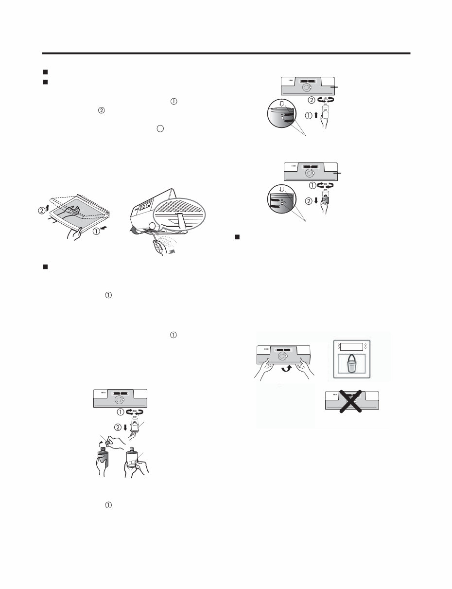
Install Water Filter (Applicable to some models only) Before Installing water filter 1. Before installing the filter, take out the top shelf of the refrigerator after tilting it to the direction ( ) and lifting it to the direction ( ) and move it to the lower part. 2. Lamp in refrigerator compartment Installing water filter 1. Initial installation of water filter Remove the filter substitute cap by turning it counterclockwise ( ) by 90 degrees and pulling it down. Note : Keep it safe to use it later when you do not use the filter. Remove the red cap from the filter and attach the sticker. Insert the upper part of the filter ( ) after aligning with the guideline marked on the control box, and fasten it by turning it clockwise by 90 degrees. Note : Check that the guideline and the fastening indication line are aligned. 2. Replacement of water filter While holding the lower part of the filter, turn it counterclockwise ( ) by 90 degrees and pull it down. Note : Check that the guideline and the loosening indication line are aligned. After installing water filter Reassemble the lamp cover and the top shelf of the refrigerator. To place the top shelf of the refrigerator, raise the front part of the shelf a bit so that the hook of the shelf is fit into the groove. In order to clean the water filter system, drain water for about 3 min. Note : Then open the door of the refrigerator and check for water droppings on the shelf under the filter. Control box Aligning with the guide line and the fastening indication line Aligning with the guide line and the loosening indication line Control box Separation of red cap Adhesion sticker Substitute cap HOW TO INSTALL REFRIGER ATOR - 10 - Insert the tool into the marked area ( ) and push the tool to disconnect. Use the tool with the flat tip such as ( - ) screw driver. Turn the bulb counterclockwise. Max. 40 W bulb for refrigerator is used and can be purchased at a service center. 3 3
Are you looking to troubleshoot and repair your LG side-by-side refrigerator? This comprehensive service and repair manual is the go-to guide used by authorized LG technicians and maintenance personnel. Whether you're a professional mechanic or a DIY enthusiast, this manual equips you with the necessary knowledge to effectively address refrigerator issues.
Within this manual, you will gain insights into safety precautions, servicing precautions, specifications, installations, repair methods, parts identification, disassembly instructions, adjustments, troubleshooting, PWB circuit diagrams, service diagnosis charts, MICOM function and circuit descriptions, refrigerating cycles, and exploded views.
Rest assured, this is the official service and repair manual, available in a high-resolution format, ensuring top-notch quality when printed. You can conveniently print this manual from any computer and printer, enabling instant access without any shipping delays. The manual comprises 94 pages and is presented in English.