CAUTION BEFORE SERVICING THE UNIT, READ THE SAFETY PRECAUTIONS IN THIS MANUAL. REFRIGERATOR SERVICE MANUAL R Model #s: 795.77562600 795.77569600 795.77564600 795.77563600 795.77572600 795.77579600 795.77573600 P/No. 3828JL8091A (Last Revision: March. 28. 2008)
Safety Precautions 1. Specification ......................................................................................................................................................................... 2. Parts Identification ............................................................................................................................................................... 3. Operation .............................................................................................................................................................................. 3-1. Explanation of Each Function ......................................................................................................................................... 3-2. Ice Maker Function.......................................................................................................................................................... 4. Wiring Diagram ..................................................................................................................................................................... 5. Adjustment ............................................................................................................................................................................ 5-1. Compressor..................................................................................................................................................................... 5-2. Positive Temperature Coefficient (PTC) – Starter ........................................................................................................... 5-3. Over Load Protector (OLP) ............................................................................................................................................. 5-4. Remove the cover Positive Temperature Coefficient (PTC) 6. Troubleshooting ................................................................................................................................................................... 6-1. Error Mode Summary ...................................................................................................................................................... 6-2. Troubleshooting With Error ............................................................................................................................................. 6-3. Troubleshooting Else ...................................................................................................................................................... 7. Component Testing Information ......................................................................................................................................... 7-1. Defrost Controller Assembly ........................................................................................................................................... 7-2. Sheath Heater ................................................................................................................................................................. 7-3. Door Heater Assembly .................................................................................................................................................... 7-4. Switch (F, R) .................................................................................................................................................................... 7-5. Solenoid .......................................................................................................................................................................... 7-6. AC Motor Assembly ........................................................................................................................................................ 7-7. Damper ........................................................................................................................................................................... 7-8. Lamp Socket ................................................................................................................................................................... 8. Disassembly Instructions .................................................................................................................................................... 9. PCB Assembly ...................................................................................................................................................................... 10. Exploded View .................................................................................................................................................................... CONTENTS - 2 - Please read the following instructions before servicing your refrigerator. 1. Unplug the power before handling any elctrical componets. 2. Check the rated current, voltage, and capacity. 3. Take caution not to get water near any electrical components. 4. Use exact replacement parts. 5. Remove any objects from the top prior to tilting the product. SAFETY PRECAUTIONS
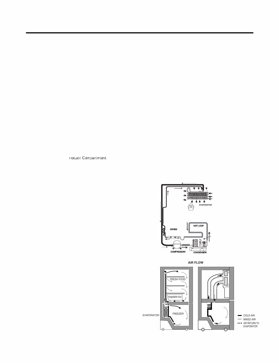
1. SPECIFICATIONS - 3 - 1-1 DISCONNECT POWER CORD BEFORE SERVICING IMPORTANT – RECONNECT ALL GROUNDING DEVICES All parts of this appliance capable of conducting electrical current are grounded. If grounding wires, screws, straps, clips, nuts or washers used to complete a path to ground are removed for service, they must be returned to their original position and properly fastened. 1-2 IMPORTANT NOTICE This information is intended for use by individuals possessing adequate backgrounds of electrical, electronic and mechanical experience. Any attempt to repair a major appliance may result in personal injury and property damage. The manufacturer or seller cannot be responsible for the interpretation of this information, nor can it assume any liability in connection with its use. 1-3 ELECTRICAL SPECIFICATIONS Temperature Control (F ) ...-6°F to +8°F Defrost Control ...................Total Comp Running Time 7 hrs Defrost Thermostat .......................................................46°F Electrical Rating : 115VAC, 60Hz.................................1-5 A Maximum Current Leakage.......................................0.5 mA Maximum Ground Path Resistance ....................0.14 Ohms Energy Consumption .....25 cu.ft. 579 kWh/yr (Energy Star) 1-4 NO LOAD PERFORMANCE CONTROL POSITION: MID/MID And Ambient of: ..................70°F ..................................90°F Fresh Food, °F ....................33°F to 41°F.........33°F to 41°F Frozen Food, °F ..................-4°F to +4°F ..........-4°F to +4°F Percent Running Time ........35%-45% .................50°F-70°F 1-5 REFRIGERATION SYSTEM Minimum Compressor Capacity Vacuum ............... 21 MIN. Minimum Equalized Pressure @ 70°F ....................................................... 49 PSIG @ 90°F ....................................................... 56 PSIG Refrigerant R134a ................................................. 4.41 oz. Compressor ..................................................... 956 BTU/hr 1-6 INSTALLATION Clearance must be provided at top, sides and rear of the refrigerator for air circulation. AT TOP ......................................................................... 2 in AT SIDES ...................................................................... 1 in AT REAR ...................................................................... 1 in 1-7 REPLACEMENT PARTS Relay..............................................................6748C-0004D Overload ........................................................6750C-0004R Defrost Thermostat........................................6615JB2005H Defrost Heater ...............................................5300JK1005D Evaporator Fan Motor....................................4681JK1004E Capacitor (Running) .....................................0CZZJB2014B *0CZZJB2012H *0CZZJB2012K Compressor (Hi-Side) ...................................TCA31748001 Evaporator (Lo-Side) ......................................5421JJ1007A Condenser......................................................5403JJ1004B Dryer ..............................................................5851JA2002P Condenser Fan Motor ...................................4681JB1029D Temperature Control ..............................3551JA1132L(SW) 3551JA1132M(ST) 3551JA1132N(WB) 3551JA1132P(BI) Main Control ....................................................EBR3491102 Ice Fan Motor ................................................4681JB1029E *OPTIONAL 1-8 AIR FLOW / CIRCULATION D’AIR EVAPORTOR FAN MOTOR CONDENSER FAN MOTOR ICE ROOM
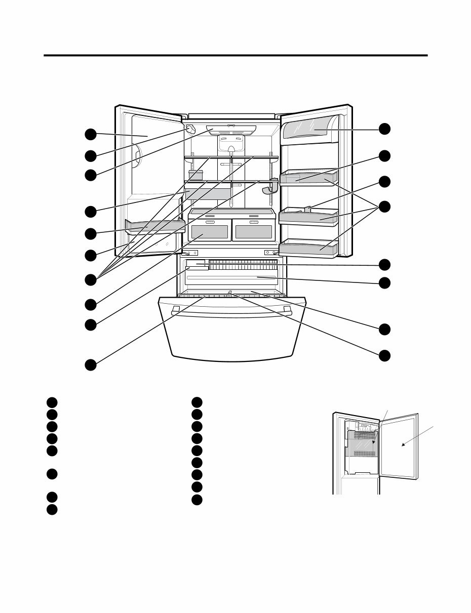
2. PARTS IDENTIFICATION - 4 - A B F N M E L H G C P C Q O D I K J Refrigerator Light Filter (Inside) Modular Door Bins Refrigerator Shelves Supra Fresh Crisper with Tilt-Out Compartment Ice Room (ICEMAKER and ICE BIN) Pull out Drawer Turbo Motor Tilt-Out Door Basket Durabase Divider Ice Bin Water Tank Cover Snack Pan Egg Box Dairy Bin Bottle Holder A B C D E F G H I J K L M N O P Q Ice Bank Ice Door
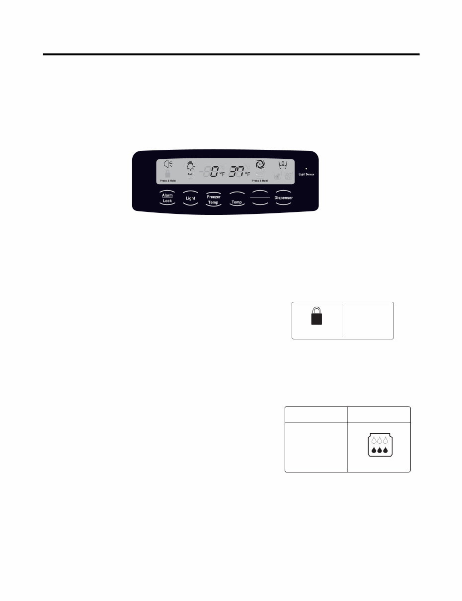
3. OPERATION - 5 - 3-1. Explanation Of Each Function 1. Function (1) When the appliance is plugged in, it is set to 37 °F for the refrigerator and 0 °F for the freezer. You can adjust the refrigerator and the freezer control temperature by pressing the ADJUST button. (2) When the power is initially applied or restored after a power failure, maintains its previously set temperature. . 2 How to Toggle the Display between °F and °C (1) The initial setting is °F and the display temperature mode can be changed from °F to °∆C or °∆C to °∆F by pressing and holding the FRZ TEMP and the REF TEMP keys at the same time for over 5 seconds. 3. Lock function (dispenser and display button lock) (1) When the refrigerator is first turned on, the buttons are not locked. The display panel shows the padlock unlocked icon. (2) To lock the display, the dispenser, and the control panel, press and hold the LOCK button for 3 seconds. The locked pad lock icon is displayed. (3) The LOCK button is the only control feature that remains active in the locked state. The buzzer sound, other control buttons, and the dispenser are deactivated. (4) To release from the locked state, press and hold the LOCK button again for 3 seconds. 4. Filter condition display function (1) There is a replacement indicator icon for the filter cartridge on the dispenser. (2)The water filter should be replaced approximately every six months. (3) The water filter icon will turn on every six months to remind you to replace. (4) After replacing the filter, press and hold the lock button more than 3 seconds. This will turn off the reminder icon and reset the timer. Refrigerator Ultra lce Filter Reset Ex) In selecting "LOCK" Ex) In selecting "LOCK" again Press & Hold Press & Hold In initial Power On / Filter RESET Replace indicator light on Classification Filter Status Display Press & Hold Press & Hold
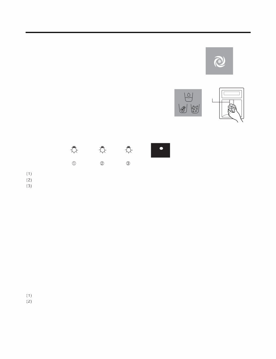
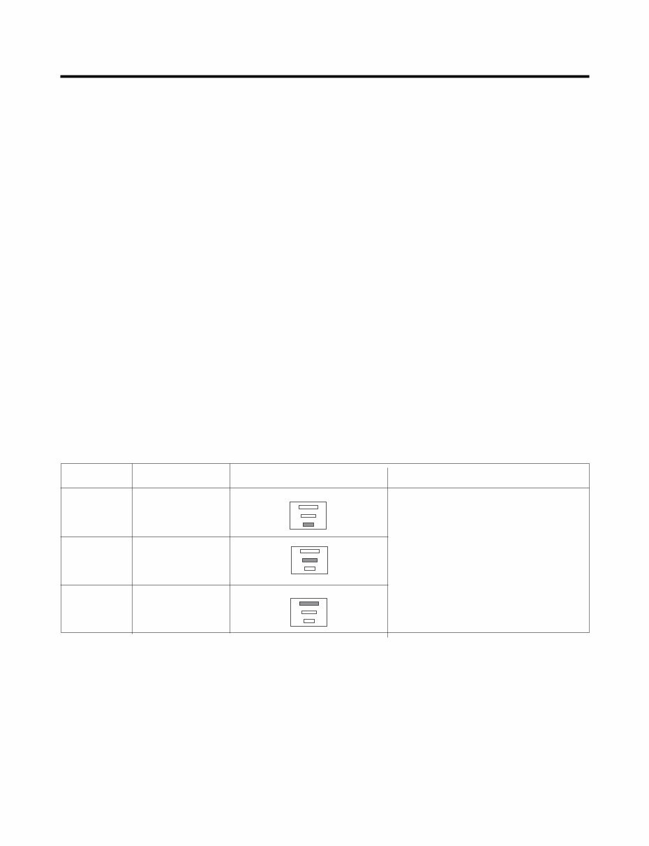
- 6 - 5. Ice Plus Selection Please select this function for quick freezing. (1) The ICE PLUS option starts counting its 24-hours period every time the button is pressed. (2) The ICE PLUS function automatically turns off after twenty-four hours pass. 6. Dispenser Use Selection You can select water or ice. * Select water, crushed ice, or ice cubes by cycling through the selections when pressing the DISPENSER button, * Hold your cup in the dispenser for a few seconds after dispensing ice or water to allow the last pieces of ice or drops of water to fall into the cup. 7. Dispenser Light Whenever the light button is pressed, the display changes as shown below. Normal status: When dispenser is operated, DISPENSER LIGHT is ON. AUTO status: Detecting the lighting of room by LIGHT SENSOR, DISPENSER LIGHT is on and off automatically. ON status: DISPENSER LIGHT is on continuously. 8. Control Of Freezer Fan Motor (1) Freezer fan motor has high and standard speeds. (2) High speed is used at power-up, for Ice Plus, and when refrigerator is overloaded. Standard speeds is used for general purposes. (3) To improve cooling speed, the RPM of the freezer fan motor changes from normal speed to high. (4) High speed (2700RPM) : Initial power on or load corresponding operation, Ice Plus Normal speed (2400RPM) : General working conditions. (5) Fan motor stops when a refrigerator or freezer door opens. 9. Cooling Fan Motor (1) The cooling fan is switched ON and OFF in conjunction with the compressor. (2) The cooling fan runs at a single speed. (3) The Failure sensing method is the same as in the fan motor of the freezing fan motor(refer to failure diagnosis function table for failure display). 10. Icing Fan The Icing Fan is controlled by the the sensor on the top of the ice room. The Failure sensing method is the same as in the fan motor of the freezer (refer to failure diagnosis function table for failure display) Pressing Switch Auto Auto on Light Sensor
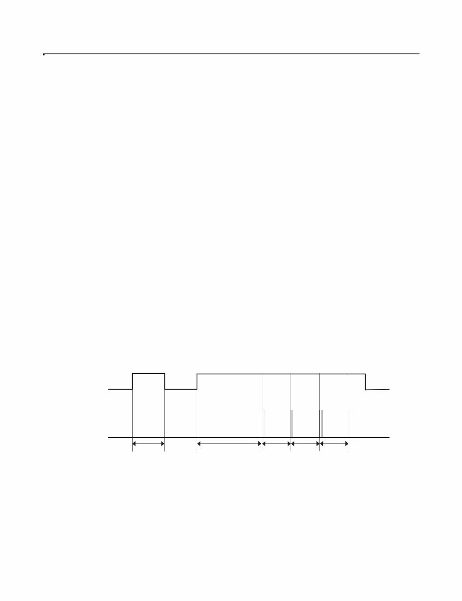
- 7 - 11. Ice Plus (1) The purpose of this function is to intensify the cooling speed of freezer and to increase the amount of ice. (2) Whenever selection switch is pressed, selection/release, the LED will turn ON or OFF. (3) If there is a power outage and the refrigerator is powered on again, Ice Plus will be canceled. (4) To activate this function, press the Ice Plus key and the LED will turn ON. This function will remain activated for 24 hours. The first three hours the compressor and Freezer Fan will be ON. The next 21 hours the freezer will be controlled at the lowest temperature. After 24 hours or if the Ice Plus key is pressed again, the freezer will return to its previous temperature. (5) During the first 3 hours: • Compressor and freezer fan (HIGH RPM) run continuously. • If a defrost cycle begins during the first 90 minutes of Ice Plus, the Ice Plus cycle will complete its cycle after defrosting has ended. If the defrost cycle begins when Ice Plus has run for more than 90 minutes, Ice Plus will run for two hours after the defrost is completed. • If Ice Plus is pressed during defrost, Ice Plus LED is on but this function will start seven minutes after defrost is completed and it shall operate for three hours. • If Ice Plus is selected within seven minutes after compressor has stopped, the compressor (compressor delays seven minutes) shall start after the balance of the delay time. • The fan motor in the freezer compartment runs at high speed during Ice Plus. (6) For the rest of the 21 hours, the freezer will be controlled at the lowest temperature. 12. Freezer and Refrigerator Lamp Auto Off (1) To avoid heat damage caused by the lamp, it is turned off automatically when the refrigerator door is open for more than 7 minutes. 13. Alarm for Open Door (1) This feature sounds a buzzer when the freezer or refrigerator door is not closed within 1 minute after it is opened. (2 One minute after the door is opened, the buzzer sounds three times each for one half seconds. These tones repeat every 30 seconds. (3) The alarm is cancelled when the freezer or the refrigerator is closed. Closed Open Closed Open 3 Times 3 Times 3 Times 3 Times Closed Within 1 min. 1 min. 30 sec 30 sec 30 sec Freezer Door or Refrigerator Door Buzzer
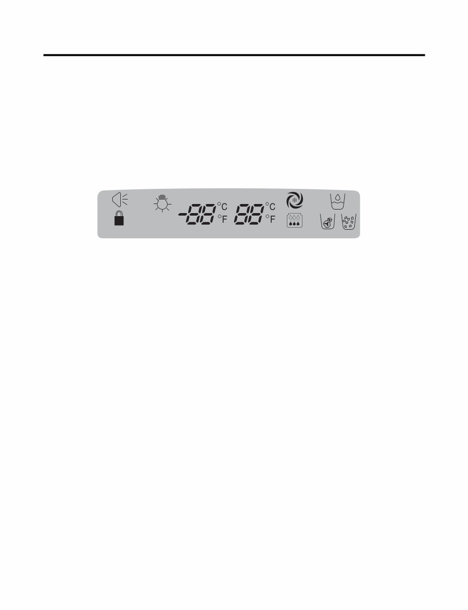
- 8 - 14. Defrosting (removing frost) (1) Defrosting starts each time the COMPRESSOR running time reaches 7 hours. (2) For initial power on or for restoring power, defrosting starts when the compressor running time reaches 4 hours. (3) Defrosting stops if the sensor temperature reaches 46.4°F (8°C) or more. If the sensor doesn’t reach 46.4°F (8°C) in 2 hours, the defrost mode is malfunctioning. (Refer to the defect diagnosis function, 15.) (4) Defrosting won’t function if its sensor is defective (wires are cut or short circuited) 15. Defect Diagnosis Function (1) Automatic diagnosis makes servicing the refrigerator easy. (2) When a defect occurs, the buttons will not operate; but the tones will sound. (3) When the defect CODE removes the sign, it returns to normal operation (RESET). (4 The defect CODE shows on the Refrigerator and Freezer Display. ✽ LED check function: Press Ice Plus and Freezer buttons for a second, display LED graphics on. If releasing the button, the LED graphic displays the previous status. Press & Hold Press & Hold Auto on
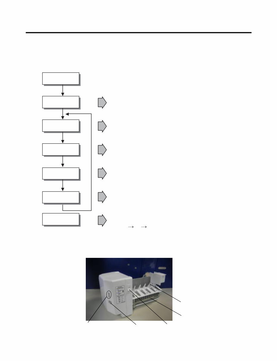
- 9 - 3-2. Ice Maker Function 1. Operation Principle of icemaker (1) Turning the Icemaker stop switch off (O) stops the ice making function. (2) Setting the Icemaker switch to OFF and then turning it back on will reset the icemaker control. • Adjusts EJECTOR to Start Position with power on. Power On Start Position Icemaking Mode Harvest Mode Fill Park Position Test Mode • Waits until water becomes ICE after starting the icemaking operation. • Runs MOTOR to drop ice from the tray into the ICE BIN. (During harvest mode, check if the ice bin is full.) • Performs Ice Making Mode after supplying water by operating the SOLENOID in ICE VALVE. • To operate LINE and SERVICE, press and hold the Cube Size button for 3 seconds. The icemaker will run through 3 stages: Harvest Fill Icemaking. • Reaches Start Position Cube Size Indicator Light Cube Size Selection Button Power Switch Automatic Shut off Arm EJECTOR
- 10 - 2. Icemaking Mode (1) Icemaking refers to the freezing of supplied water in the ice tray. Complete freezing is assured by measuring the temperature of the tray with Icemaking SENSOR. (2) Icemaking starts after completion of the water fill operation. (3) The icemaking function is completed when the sensor reaches 1 9 °∆F (-7 °∆C), 55 minutes after starting. NOTE : After the icemaker power is ON, the icemaker heater will be on for test for 6 seconds. 3. Harvest Mode (1) Harvest (Ice removing) refers to the operation of dropping cubes into the ice bin from the tray when icemaking has completed. (2) Harvest mode: • The Heater is ON for 30 seconds, then the motor starts. • The feeler arm senses the quantity of ice in the ice storage bin while rotating with the EJECTOR. A. Ice storage bin is full : The EJECTOR stops (heater off). B. Ice storage bin is not full : The EJECTOR rotates twice to open for ice. * If the EJECTOR does not rotate once within 5 minutes in B mode, separate heater control mode starts operating to prevent the EJECTOR from being constrained. (It is recommended that the user open for ice to return to normal mode.) 4. Fill/Park Position (1) Once a normal harvest mode has been completed, the water solenoid will be activated. (2) The amount of water is adjusted by pressing the fill key repeatedly. This changes the time allowed for fill as illustrated in the table below. Water supply amount TABLE STAGE TIME TO SUPPLY INDICATIONS REMARKS 1 2 3 5 sec. 5.5 sec. (FIRST STAGE) 6 sec. The water amount will vary depending on the water control switch setting as well as the water pressure of the connected water line.
You're Reading a Preview
What's Included?
Lifetime Access
Fast Download Speeds
Online & Offline Access
Access PDF Contents & Bookmarks
Full Search Facility
Print one or all pages of your manual
$36.99
Kenmore 7756 7757 French door refrigerator service manual
This service and repair manual for the Kenmore 7756 + 7757 French door refrigerator is an essential resource for both professional mechanics and DIY enthusiasts. It contains comprehensive information, including product specifications, parts identification, disassembly and assembly instructions, troubleshooting, adjustment procedures, wiring diagram, printed circuit board details, component testing, error codes, exploded views, and a parts list catalog.
The manual is meticulously detailed and includes illustrated step-by-step instructions and high-resolution images to guide you through the repair and servicing process effectively.
It is available in English and comes in a PDF format with 78 pages. Upon purchase, you will have instant access to the manual, eliminating shipping costs and waiting time for postal delivery, allowing you to commence repairs promptly.
Reviews
Q&A
Recently Viewed
5,521,897Happy Clients
2,594,462eManuals
1,120,453Trusted Sellers
15Years in Business
Price:
Actual Price:
Kenmore 7756 7757 French door refrigerator service manual