

CAUTION
BEFORE SERVICING THE UNIT,
READ THE SAFETY PRECAUTIONS IN THIS MANUAL.
Model #s:
REFRIGERATOR
SERVICE MANUAL
795.74092.41*
795.74093.41*
795.74099.41*
P/No. MFL68488631

- 2 -
CONTENTS
SAFETY PRECAUTIONS ....................................................................................................................................................... 2
1. SPECIFICATIONS .......................................................................................................................................................... 3-4
2. PARTS IDENTIFICATION .................................................................................................................................................. 5
3. DISASSEMBLY .............................................................................................................................................................6-21
REMOVING AND REPLACING REFRIGERATOR DOORS ............................................................................................. 6
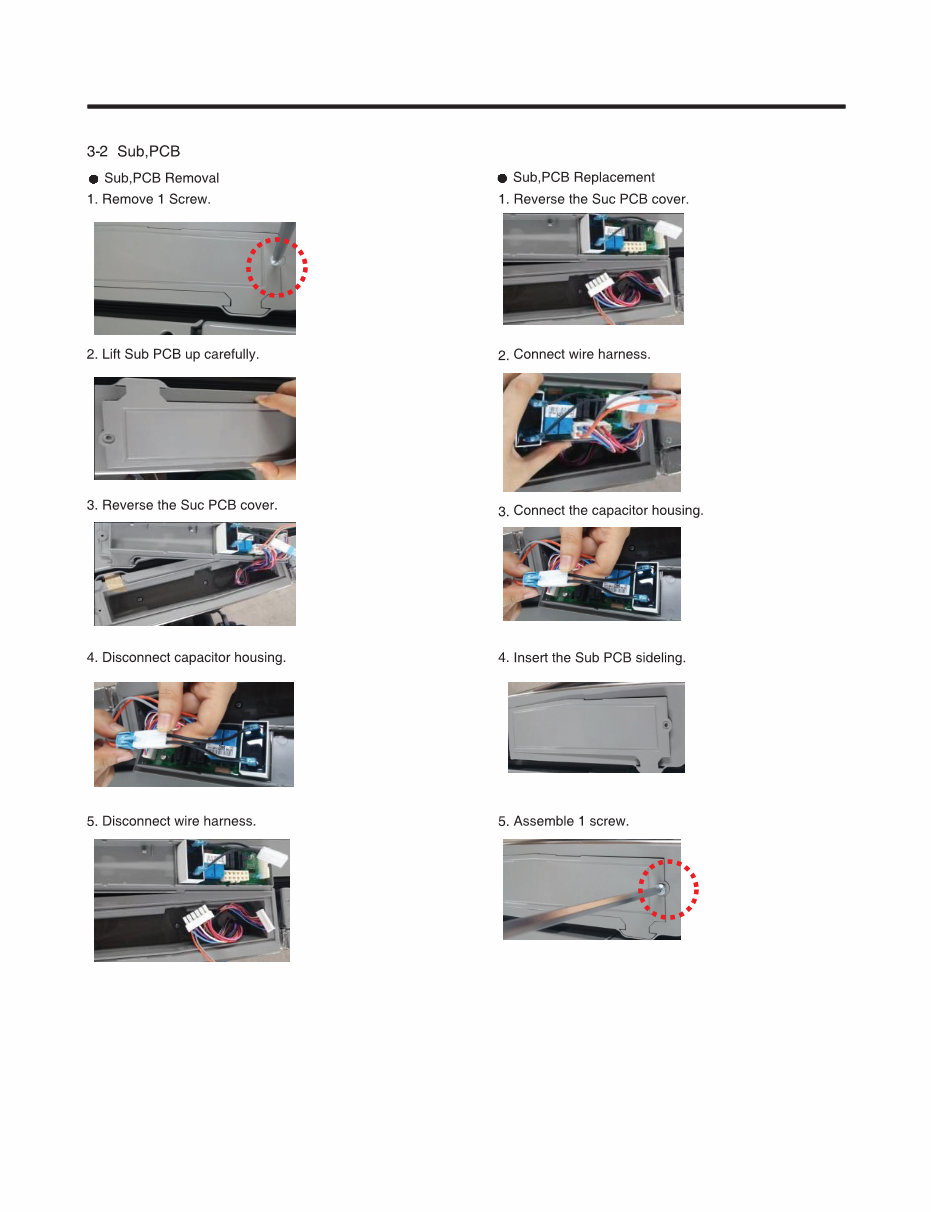
SUB PCB ............................................................................................................................................................................. 7
DOOR .................................................................................................................................................................................. 8
DOOR ALIGNMENT .......................................................................................................................................................... 9
FAN AND FAN MOTOR .................................................................................................................................................... 9
DEFROST CONTROL ASSEMBLY ................................................................................................................................. 10
REFRIGERAOTR LIGHT................................................................................................................................................... 11
MULTI DUCT ................................................................................................................................................................... 12
AIR FILTER ....................................................................................................................................................................... 13
MAIN PCB ......................................................................................................................................................................... 13
DISPENSER COVER DISASSEMBLY .............................................................................................................................. 13
DISPLAY PCB REPLACEMENT ..................................................................................................................................... 14
FUNNEL REPLACEMENT ................................................................................................................................................ 14
SUB PCB FOR WORKING DISPENSER .......................................................................................................................... 14
CAP DUCT REPALCEMENT ............................................................................................................................................ 14
CAP DUCT MOTOR REPLACEMENT .............................................................................................................................. 14
ICE CORNER DOOR REPLACEMENT .......................................................................................................................... 15
ICEMAKER REPLACEMENT ............................................................................................................................................ 15
HOW TO REMOVE A ICE BIN ........................................................................................................................................ 16
HOW TO PLACE ICE BIN IN POSITION.......................................................................................................................... 16
PULL OUT DRAWER........................................................................................................................................................ 17
HOW TO REMOVE AND REINSTALL THE PULLOUT DRAWER ............................................................................. 18-19
WATER VALVE DISASSEMBLY METHOD .................................................................................................................... 20
FAN AND FAN MOTOR DISASSEMBLY METHOD ....................................................................................................... 20
CAUTION : SEALED SYSTEM REPAIR........................................................................................................................... 21
3 WAY VALVE SERVICE .................................................................................................................................................. 21
4. ADJUSTMENT ................................................................................................................................................................ 22
5. CIRCUIT DIAGRAM ........................................................................................................................................................ 23
6. TROUBLESHOOTINTG ............................................................................................................................................. 24-25
7. PCB PICTURE ........................................................................................................................................................... 26-27
8. TROUBLESHOOTING .............................................................................................................................................. 28-68
9. REFERENCE .............................................................................................................................................................. 69-72
10. COMPONENT TESTING INFORMATION ...................................................................................................................73-83
11. COMPRESSOR TROUBLESHOOTING ................................................................................................................... 84-96
12. ICEMAKER OPERATING METHOD AND TROUBLE SHOOTING ......................................................................... 97-98
13. DESCIPTION OF FUNCTION & CIRCUIT OF MICOM ........................................................................................... 99-102
SAFETY PRECAUTIONS
Please read the following instructions before servicing your refrigerator.
1. Unplug the power before handling any elctrical componets.
2. Check the rated current, voltage, and capacity.
3. Take caution not to get water near any electrical components.
4. Use exact replacement parts.
5. Remove any objects from the top prior to tilting the product.
- 3 -
1. SPECIFICATIONS
1-1 DISCONNECT POWER CORD BEFORE
SERVICING IMPORTANT - RECONNECT ALL
GROUNDING DEVICES
All parts of this appliance capable of conducting electrical
current are grounded. If grounding wires, screws, straps,
clips, nuts or washers used to complete a path to ground
are removed for service, they must be returned to their
original position and properly fastened.
1-2 IMPORTANT NOTICE
This information is intended for use by individuals
possessing adequate backgrounds of electrical, electronic
and mechanical experience. Any attempt to repair a major
appliance may result in personal injury and property
damage. The manufacturer or seller cannot be responsible
for the interpretation of this information, nor can it assume
any liability in connection with its use.
1-7 REPLACEMENT PARTS
Overload Protector ........................................ 6750CL0001D
R-Defrost Thermostat .................................. ACM73919201
F-Defrost Thermostat .................................. ACM73919202
F-Defrost Heater .......................................... MEE62225112
R-Defrost Heater ......................................... MEE62105206
F-Evaporator Fan Motor ............................... EAU60694527
R-Evaporator Fan Motor ............................... EAU61505013
Capacitor (Running) ..................................... EAE58905704
Compressor (Hi-Side) ................................... TCA36491302
R-Evaporator(Lo-Side) .................................. ADL73881001
F-Evaporator(Lo-Side) .................................. ADL73980910
Conderser .................................................... ACG73645002
Dryer .............................................................. 5851JA2007U
Condenser Fan Motor .................................. EAU62863103
Temperature Control ........................... ACQ85571111(SW)
ACQ85571112(ST)
ACQ85571113(WB)
Main Control .................................................. EBR78940606
Ice Fan Motor ................................................ EAU61524010
31.7cu,ft
795.74092.41*
795.74093.41*
795.74099.41*
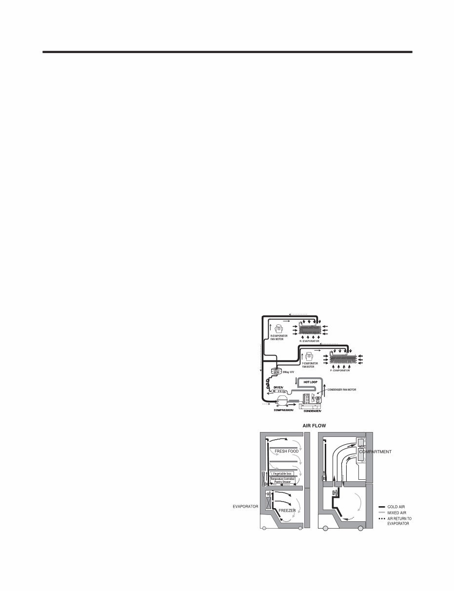
1-8 AIR FLOW / CIRCULATION D’AIR
1-3 ELECTRICAL SPECIFICATIONS
Temperature Control (Freezer Compartment) . -6°F to +8°F
Defrost Control ......Total Comp Running Time: 7 hrs~50 hrs
Defrost Thermostat ...................................................... 41°F
Electrical Rating : 115VAC, 60Hz ............................... 3.5 A
Maximum Current Leakage ..................................... 0.5 mA
Maximum Ground Path Resistance ................... 0.14 Ohms
Energy Consumption ... 31.7cu.ft. 768 kwh/yr (Energy Star)
1-5 REFRIGERATION SYSTEM
Minimum Compressor Capacity Vacuum ............... 21 MIN.
Minimum Equalized Pressure
@ 70°F .......................................................... . 49 PSIG
@ 90°F ........................................................... 56 PSIG
Refrigerant R134a .................................................... 4.83oz
Compressor .................................................... 1075 BTU/hr
1-6 INSTALLATION
Clearance must be provided at rear of the refrigerator for air
circulation.
AT REAR ........................................................................ 2 in
1-4 NO LOAD PERFORMANCE
CONTROL POSITION: MID/MID
And Ambient of : ................ 70°F ................................ . 90°F
Fresh Food, °F ................. 33°F to 41°F ....... 33°F to 41°F
Frozen Food, °F ............... -4°F to +4°F ......... -4°F to +4°F
Percent Running Time ...... 50%-65% ................. 65%-80%
- 4 -
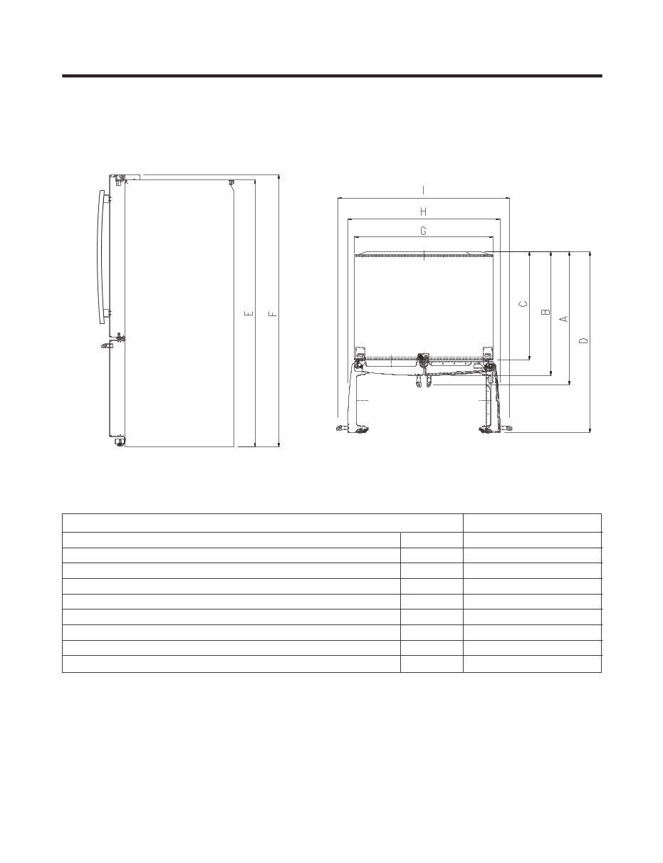
Depth w/ Handles
Depth w/o Handles
Depth w/o Door
Depth (Total with Door Open)
Height to Top of Case
Height to Top of Door Hinge
Width
Width (door open 90 deg. w/o handle)
Width (door open 90 deg. w/ handle)
A
B
C
D
E
F
G
H
I
37 1/8 in
34 5/8 in
30 3/8 in
49 in
68 7/8 in
70 1/4 in
35 3/4 in
40 in
45 in
Description 795.7409*
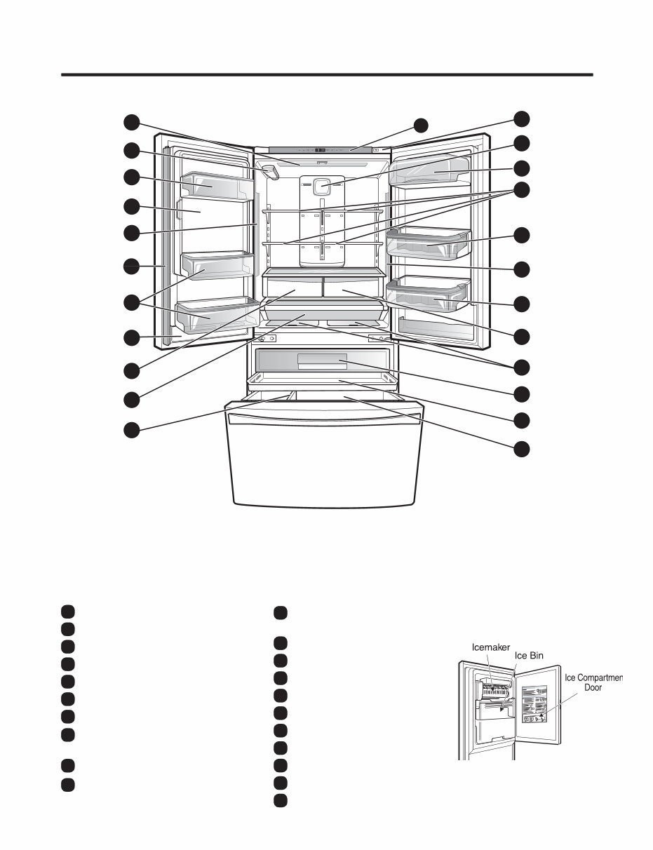
2. PARTS IDENTIFICATION
- 5 -
A
B
G
E
H
E
P
I
K
O
D
S
R
G
F
C
C
M
L
T
J
N
Q
U
Refrigerator Light A
Water Filter B
Adjustable Door Bins C
Adjustable Dairy Bin D
Fixed Door Bins E
Refrigerator Shelves F
Refrigerator Light (side) G
Temperature Controlled
Pantry Drawer
K
Top Pullout Drawer L
Middle Pullout Drawer M
Durabase N
Durabase Divider O
Water Tank Cover P
Articulating Mullion Q
Air Filter R
Kenmore Connect Speaker S
Convenience Bin T
Ice Compartment
(Icemaker and Ice Bin)
H
Humidity Controlled Crisper I
Air Tight Crisper J
Use this page to become more familiar with the parts and features of your refrigerator.
NOTE: This guide covers several di erent models. The refrigerator you have purchased may have some or all
of the items listed below. The locations of the features shown below may not match your model.
Control Panel U
3. DISASSEMBLY
- 6 -
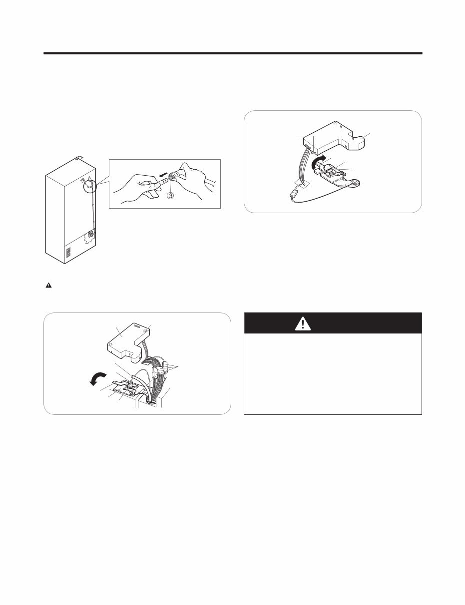
3-1 REMOVING AND REPLACING REFRIGERATOR DOORS
To remove the left refrigerator door:
Pull the water tube out of the fitting while pressing the
release ring on the fitting.
When you pull out the tube, first you have to push the
collet by opposite direction of arrow in the upper picture
and tube pull out by direction of arrow.
To remove the Right refrigerator door:
Open the door. Remove the top hinge cover screw (1).
Lift up the cover (2).
Remove the cover.
Rotate the hinge lever (3) clockwise.
Lift the top hinge (4) free of the hinge lever latch (5).
IMPORTANT: When lifting the hinge free of the latch,
be careful that the door does not fall forward.
Open the door. Remove the top hinge cover screw (1).
Use a flat-head screwdriver to pry back the hooks (not
shown) on the front underside of the cover (2).
Lift up the cover.
Remove the cover. Pull out the tube (3).
Disconnect all the wire harnesses (4).
Remove the grounding screw(5)
Rotate hinge lever (6) counterclockwise.
Lift the top hinge (7) free of the hinge lever latch (8).
IMPORTANT: When lifting the hinge free of the latch, be
careful that the door does not fall forward.
Lift the door from the middle hinge pin and remove the
door.
Place the door, inside facing up, on a nonscratching
surface.
CAUTION: Before you begin, remove food and
bins from the doors.
(2)
(3)
(4)
(5)
(1)
(1)
(2)
(3)
(6)
(7)
(8)
(4)
(5)
WARNING
Explosion Hazard
Disconnect electrical supply to the refrigerator before
installing. Failure to do so could result in death or
serious injury.
Do not put hands or feet or other objects into the air
vents, base grille, or bottom of the refrigerator.
You may be injured or receive an electrical shock.
Be careful when you work with the hinge, base grille,
and stopper. You may be injured.
- 7 -
- 8 -
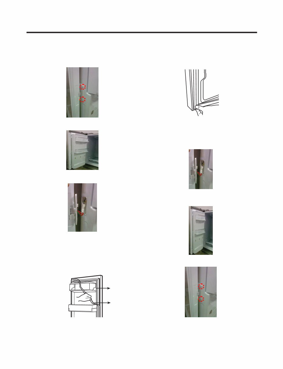
1. Remove gasket
Remove the gasket from gasket channel at doorliner as
shown in the illustration below.
3-3 DOOR
Mullion Removal
1. Remove 2 screws.
Door Gasket Removal
2. Lift mullion up carefully.
3. Disconnect wire harness.
Door Gasket Replacement
1. Insert gasket into channel
Insert and press gasket into channels at doorliner.
2. Insert mullion into channel.
Insert the mullion into channel at door as shown below.
Mullion Replacement
1. Connect wire harness.
3. Assemble 2 screws.
Gasket
Gasket
Channel
- 9 -
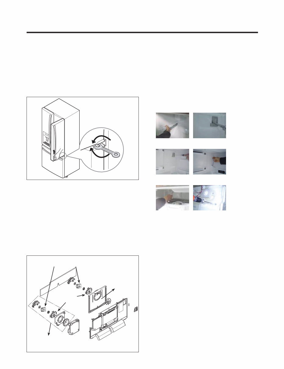
* Ice Fan Assembly Replacement
1) Remove the plastic guide for slides on left side by
unscrewing phillips head screws.
2) Pull out the cover sensor to disassemble by using tools
shown in the figure.
3) Pull out the cover grille to disassemble by using tools
shown in the figure.
4) Put your hand into the inside of grille to disassemble
shown in the figure.
5) Disconnect wire harness of the grille assembly.
6) Remove the Ice fan assembly by loosening all screws.
(1) (2)
(3) (4)
(5) (6)
3-4 Door Alignment
If the level of refrigerator doors is uneven, follow the
instructions below to align the doors:
Turn the leveling legs (CCW) to raise or (CW) to lower the
height of the front of the refrigerator by using flat blade
screw driver or 11/32" wrench. Use the wrench (Included
with the User Manual) to adjust the bolt in the door hinge to
adjust the height. (CW to raise or CCW to lower the height.)
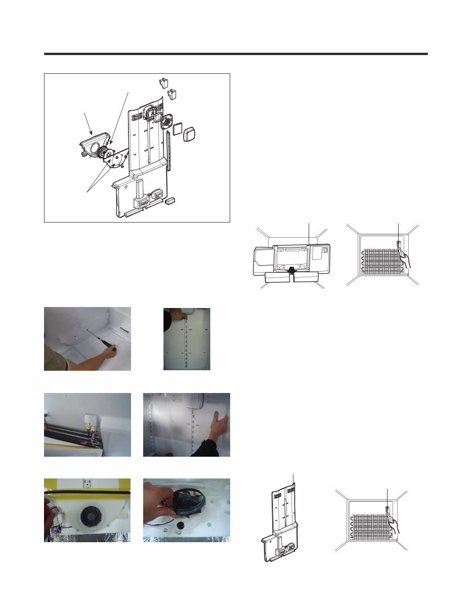
3-5 FAN AND FAN MOTOR
1. Remove the freezer drawer.
2. Remove the plastic guide for slides on left side by
unscrewing phillips head screws.
3. Remove the grille assembly by removing four screws
and pulling the grille assembly forward.
4. Remove the Fan Motor assembly by loosening 3 screws
and disassembling the shroud.
5. Pull out the fan and separate the Fan Motor and Bracket
Motor.
1. Remove all shelf and guide rail on left side.
2. Remove upper and lower Caps by using a flat
screwdriver. And then, remove 2 screws under Caps.
3. Pull out the Multi Duct outward slightly.
4. Disconnect the lead wire on bottom as shown.
5. Grip both side of Multi Duct, pull it out.
6. Remove the Shroud Refrigerator by loosening 4 screws
and disassembling the Multi Duct.
7. Pull out the Fan Motor
3-4-1 FAN AND FAN MOTOR(Freezer Room)
3-4-2 FAN AND FAN MOTOR(Refrigerator Room)
FAN MOTOR
BRACKET
MOTOR
Shroud
Up
Down
Ice Fan Assembly
- 10 -
3-6 DEFROST CONTROL ASSEMBLY
3-5-1 DEFROST CONTROL ASSEMBLY(Freezer Room)
3-5-2 DEFROST CONTROL ASSEMBLY
(Refrigerator Room)
Figure 1
Figure 2
GRILLE ASSEMBLY
DEFROST-CONTROL
ASSEMBLY
Figure 1
Figure 2
Multi Duct
DEFROST-CONTROL
ASSEMBLY
* Fan Motor Replacement
1) Remove guide rail on left side.
2) Remove Caps and 2 screws under Caps
3) Disconnect the lead wire
4) Grip both side of Multi Duct, pull it out.
4) Remove 4 screws of Shroud Refrigerator on back of
Multi Duct.
5) Remove Shroud Refrigerator and Replace Fan Motor.
(1) (2)
(3) (4)
(5) (6)
Defrost Control assembly consists of Defrost Sensor and
FUSE-M.
The Defrost Sensor works to defrost automatically.
It is attached to the metal side of the Evaporator and
senses its temperature.
At 46F(8°C), it turns the Defrost Heater off.
Fuse-M is a safety device for preventing over-heating of the
Heater when defrosting.
1. Pull the Multi Duct (Figure 1)
2. Separate the connector with the Defrost Control
assembly and replace the Defrost Control assembly
after cutting the Tie Wrap. (Figure 2)
Defrost Control assembly consists of Defrost Sensor and
FUSE-M.
The Defrost Sensor works to defrost automatically. It is
attached to the metal side of the Evaporator and senses its
temperature. At 46F(8°C), it turns the Defrost Heater off.
Fuse-M is a safety device for preventing over-heating of
the Heater when defrosting.
1. Pull out the grille assembly. (Figure 1)
2. Separate the connector with the Defrost Control
assembly and replace the Defrost Control assembly after
cutting the Tie Wrap. (Figure 2)
Shroud Refrigerator
Bracket Motor
Fan Motor
You're Reading a Preview
What's Included?
 Lifetime Access
Fast Download Speeds
Online & Offline Access
Access PDF Contents & Bookmarks
Full Search Facility
Print one or all pages of your manual
$36.99
Kenmore 74092 74093 74099 French door refrigerator service manual
Viewed 15 Times Today

What's Included?
Lifetime Access
Fast Download Speeds
Online & Offline Access
Access PDF Contents & Bookmarks
Full Search Facility
Print one or all pages of your manual
$36.99

Secure transaction
What's Included?
Lifetime Access
Fast Download Speeds
Online & Offline Access
Access PDF Contents & Bookmarks
Full Search Facility
Print one or all pages of your manual
Description
This service and repair manual for the Kenmore 74092, 74093, 74099 French door refrigerator is an essential resource for both professional technicians and DIY enthusiasts. It contains comprehensive information, including:
- Product Specifications
- Parts Identification
- Disassembly & Assembly Instructions
- Troubleshooting
- Adjustment Procedures
- Circuit Schematic Diagram
- Printed Circuit Board
- Component Testing
- Error Codes
- Exploded Views
- Parts List Catalog
This manual is meticulously detailed and includes illustrated pictures and step-by-step instructions for effective fridge repair and servicing. It is the official and complete service and repair manual, available in PDF format with high-resolution pages for optimal print quality.
With instant access upon payment, there are no shipping costs or waiting for postal delivery, allowing you to commence repairs promptly. The manual is in English and comprises 113 pages.


