


20
4. Alignment and Adjustments
PRECAUTION
1. High voltage is present at the high voltage terminals during any cook cycle.
2. It is neither necessary nor advisable to attempt measurement of the high voltage.
3. Before touching any oven components or wiring, always unplug the oven from its power source and
discharge the high voltage capacitor.
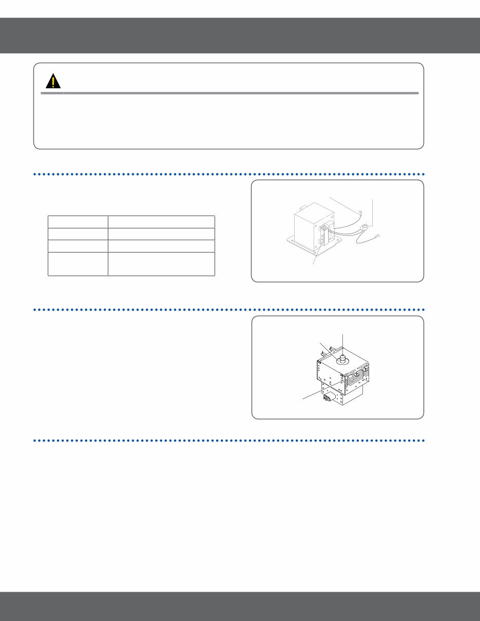
4-1 High Voltage Transformer
1. Remove connectors from the transformer terminals and
check continuity.
2. Normal resistance readings are as follows:
SHV-U1870D
Secondary Approx. 125.0 Ω + 2%
Filament Shows Continuity
Primary Approx. 0.390 Ω + 2% (Hi)
Approx. 0.430 Ω + 2% (Low)
(Room temperature = 20°C)
Filament
Terminals
Secondary
Terminal
Primary
Terminal
4-2 Magnetron
1. Continuity checks can indicate only an open filament or
a shorted magnetron. To diagnose an open filament or
shorted magnetron.
2. Isolate the magnetron from the circuit by disconnecting its
leads.
3. A continuity check across the magnetron filament terminals
should indicate one ohm or less.
4. A continuity check between each filament terminal and
magnetron case should read open.
Cooling Fins
Magnetron Antenna
Gasket Plate
4-3 High Voltage Capacitor
1. Check continuity of the capacitor with the meter set at the highest resistance scale.
2. Once the capacitor is charged, a normal capacitor shows continuity for a short time, and then indicates 9MΩ.
3. A shorted capacitor will show continuous continuity.
4. An open capacitor will show constant 9MΩ.
5. Resistance between each terminal and chassis should read infinite.
21
4. Alignment and Adjustments
4-4 High Voltage Diode
1. Isolate the diode from the circuit by disconnecting its leads.
2. With the ohm-meter set at the highest resistance scale, measure across the diode terminals. Reverse the meter
leads and read the resistance. A meter with 6V, 9V or higher voltage batteries should be used to check the front-to
back resistance of the diode (otherwise an infinite resistance may be read in both directions). The resistance of a
normal diode will be infinite in one direction and several hundred KΩ in the other direction.
4-5 Main Relay and Power Control Relay
1. The relays are located on the PCB Ass’y. Isolate them from the main circuit by disconnecting the leads.
2. Operate the microwave oven with a water load in the oven. Set the power level set to high.
3. Check continuity between terminals of the relays after the start pad is pressed.
4-6 Adjustment of Primary Switch, Door Sensing Switch and Monitor
Switch
PRECAUTION
For continued protection against radiation hazard, replace parts in accordance with the wiring diagram
and be sure to use the correct part number for the following switches: Primary and secondary interlock
switches, and the interlock monitor switch (replace all together). Then follow the adjustment procedures
below. After repair and adjustment, be sure to check the continuity of all interlock switches and the
interlock monitor switch.
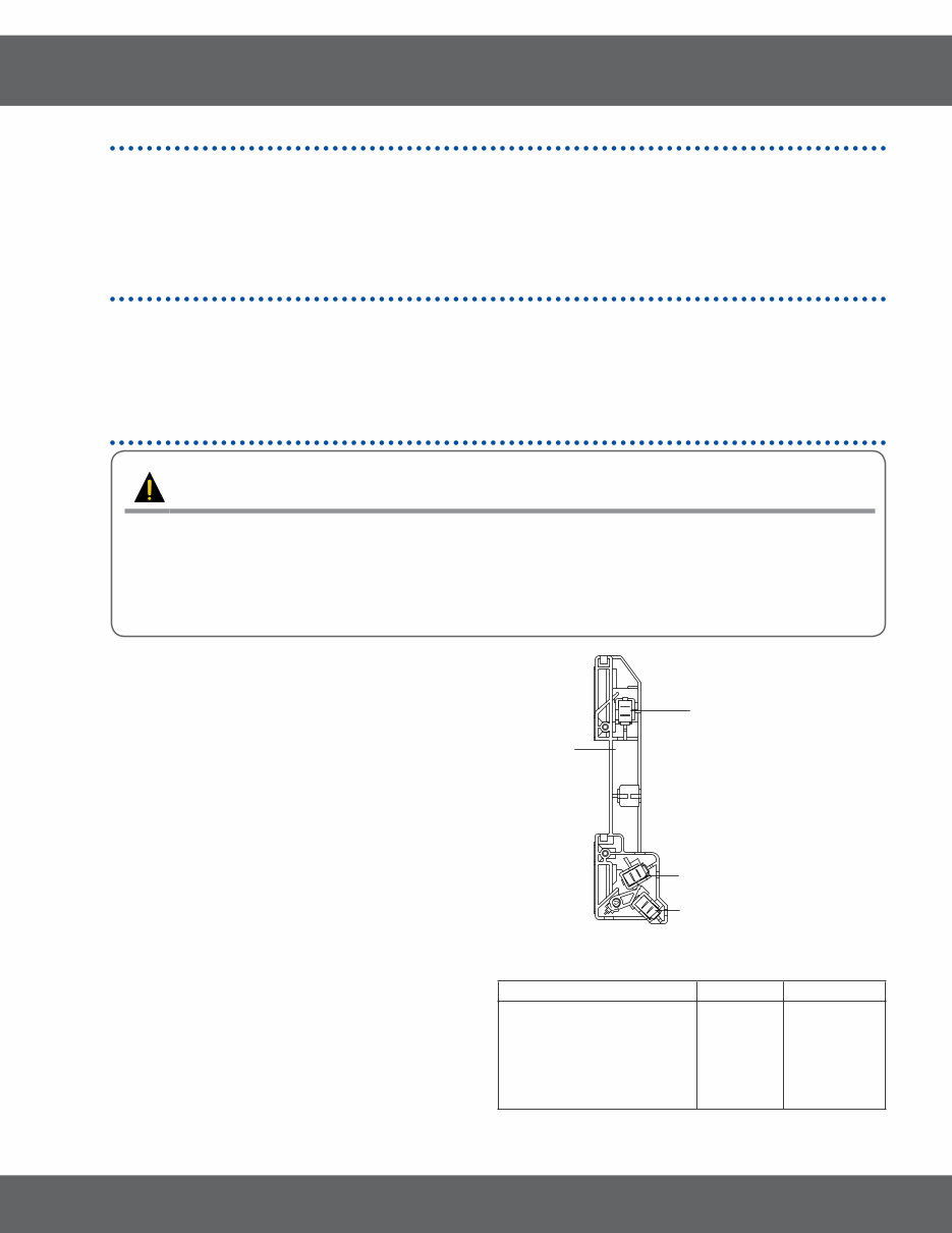
1. When mounting Primary switch and Interlock Monitor
switch to Latch Body, consult the figure.
2. No specific adjustment during installation of Primary
switch and Monitor switch to the latch body is
necessary.
3. When mounting the Latch Body to the oven
assembly, adjust the Latch Body by moving it so
that the oven door will not have any play in it. Check
for play in the door by pulling the door assembly.
Make sure that the latch keys move smoothly
after adjustment is completed. Completely tighten
the screws holding the Latch Body to the oven
assembly.
4. Reconnect to Monitor switch and check the
continuity of the monitor circuit and all latch switches
again by following the components test procedures.
5. Confirm that the gap between the switch housing
and the switch actuator is no more than 0.5mm
when door is closed.
6. Interlock Switch Replacement - When replacing
faulty switches, be sure switch mounting tabs are not
bent, broken or otherwise deficient in their ability to
secure the switches in place.
Interlock Monitor Switch
Body Latch
Door Sensing S/W
Primary Interlock S/W
(Secondary Interock Swicth)
Door Open Door Closed
Primary Interlock switch
Monitor switch(COM-NC)
Monitor switch(COM-NO)
Door Sensing S/W
(Secondary Interlock S/W)
∞
0
∞
∞
0
∞
0
0
22
4. Alignment and Adjustments
4-7 Vent Exhaust Blower Motor
THIS COMPONENT REQUIRE
REMOVAL OF MICROWAVE
OVEN FROM INSTALLATION FOR
SERVICING.
RUN CAPACITOR
The run capacitor is located behind the top grill
above the control area. The capacitor is used
for more torque and electrical phasing. Without
the capacitor the blower might run but would be
much slower.
TO TEST THE CAPACITOR
1. Remove grill, discharge capacitor and
disconnect one capacitor lead.
2. Make appropriate capacitor check (with analog
meter needle should rise then fall, cap is
charging then discharging).
TO TEST BLOWER WINDINGS:
1. Disconnect power and remove grill.
2. Open control panel and discharge capacitor.
3. Disconnent two wires to run capacitor.
Continuity test across the two wires should be
approximately 50 ohms of resistance. This test
allows you to read across all three windings at
the same time.
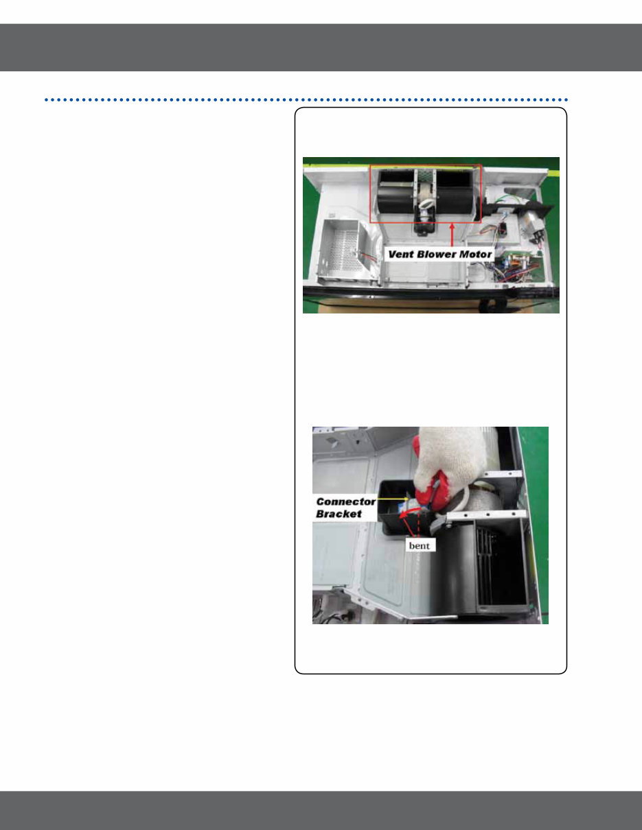
TO REMOVE VENT BLOWER
1. Remove unit from its installation.
2. Remove 3 screws securing motor to top and
back of unit and lift off. (1 screw is located
under damper.)
3. Disconnect blower plug.
NOTE: Place blower wires in routing slots to avoid
pinching of wires.
NOTE: It’s normal that connector bracket bent when
reconnecting Hood Blower Motor connector.
23
4. Alignment and Adjustments
4-8 Thermal Cutout (TCO’S)
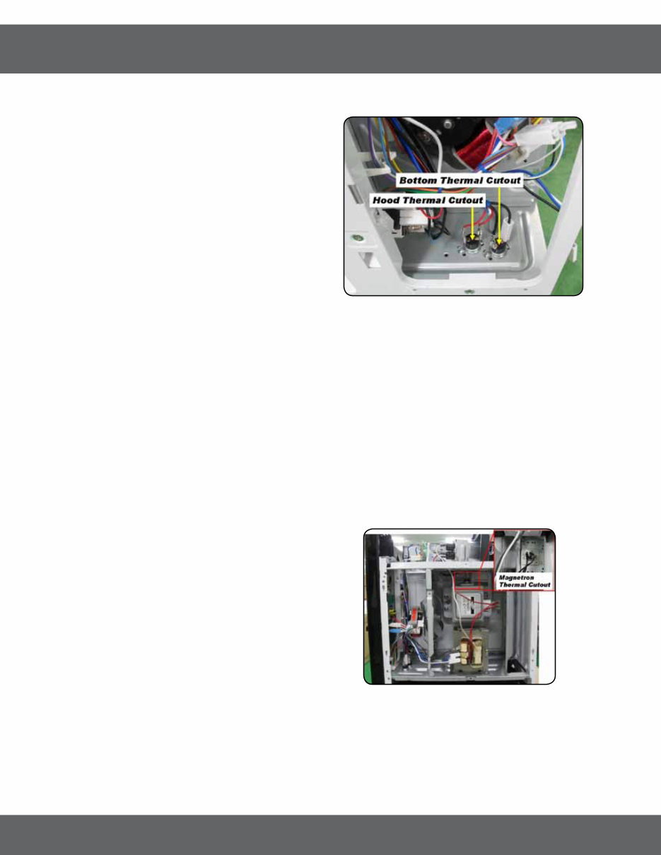
There are 4 different thermal cutouts in this unit with 4 different purposes. They are :
1. Oven thermal cutout (flame sensor), on cavity top.
2. Hood thermal cutout, inside control area on duct.
3. Bottom thermal cutout, on floor of control area.
4. Magnetron thermal cutout, on magnetron.
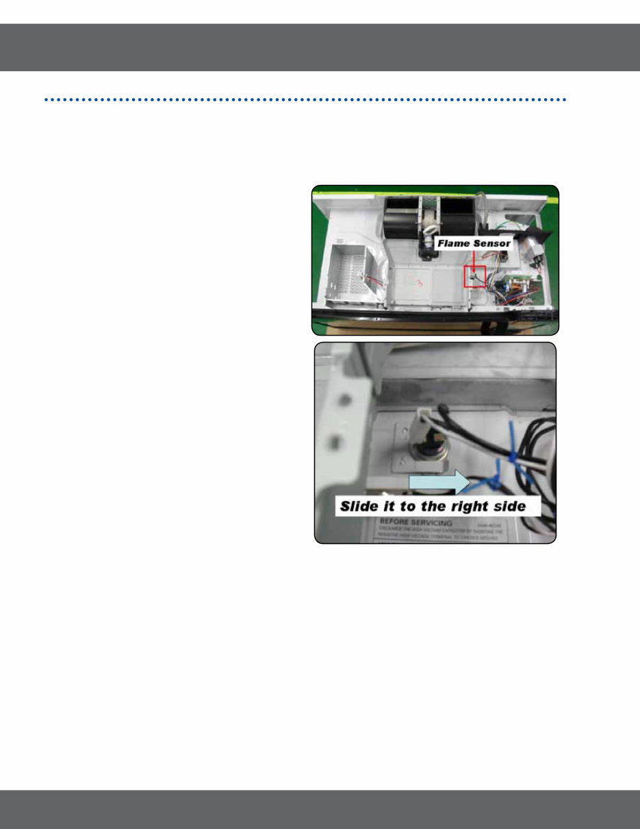
4-8-1 Oven Thermal Cutout(Flame sensor)
The oven thermal cutout(Cavity TCO) is located on
the top side of the oven cavity beside exhaust duct
with a temperature rating of 248°F(120°C) and is non-
resetable. The cutout is tightly held to the top of the
oven cavity under the duct-upper.
4-8-2 Replacement of Flame Sensor
Disconnect oven power. Remove Grill & Panel-outer.
1. Disconnect two wire leads.
2. Slide the top of the thermal cutout and pull out it
24
4. Alignment and Adjustments
4-8-3 Hood Thermal Cutout
This cutout will protect the touch control from excessive heat
by turning the vent fan on at low speed. If the surface units
of the range are used for long periods of time heat will build
up and could damage the microwave control. In order to
prevent this a thermal cutout is installed on the duct behind
the control. This cutout will close (158°F/70°C - vent fan
energized)and open (104°F/40°C - vent fan de-energized)
depending on temperatures it sense.
To Remove hood Thermal Cutout :
1. Disconnect power and remove grill.
2. Remove control box assembly.
3. Remove two wire leads and unscrew one screw capturing
cutout on duct.
NOTE : It this cutout were to open it would be difficult to detect.
The only time it functions is during an overheat condition. It
will be normally open when checked with an ohmmeter.
4-8-4 Bottom Thermal Cutout
THIS COMPONENT REQUIRE REMOVAL OF MICROWAVE OVEN FROM INSTALLATION FOR SERVICING.
During a fire on the stove the heat could be intense enough to close the Hood Thermal Cutout and force the fan
to run. While at moderate high temperature we do want it to run, however during a fire it is advantageous to NOT
have the vent fan running. So if a fire were to start on the stove top the Bottom Thermal Cutout would open at
248°F(120°C) and remove all power to the microwave oven.
This cutout is designed to not be resetable.
To Remove Magnetron Thermal Cutout :
1. Disconnect power and remove grill.
2. Remove control box assembly.
3. Remove two wire leads and unscrews one screw capturing cutout on base plate.
4-8-5 Magnetron Thermal Cutout
The magnetron thermal cutout is located above the leads
to the magnetrons. It is designed to prevent damage to
the magnetron if an overheated condition develops in the
tube to cooling fan failure, obstructed air ducts, dirty or
blocked air intake. Under normal operation, the magnetron
thermal cutout remains closed. However, when abnormally
high temperatures are reached within the magnetron, the
magnetron thermal cutout will open at 302°F(150°C) causing
the oven to shut down. After the temperature drops to 140°
F(60°C) it will reset and cooking will be able to resume.
To Remove Magnetron Thermal Cutout :
1. See ‘Removing Magnetron’.
You're Reading a Preview
What's Included?
 Lifetime Access
Fast Download Speeds
Offline Viewing
Access Contents & Bookmarks
Full Search Facility
Print one or all pages of your manual
$36.99
Samsung SMH1816B SMH1816W SMH1816S Service Manual & Repair Guide
Viewed 11 Times Today

What's Included?
Lifetime Access
Fast Download Speeds
Offline Viewing
Access Contents & Bookmarks
Full Search Facility
Print one or all pages of your manual
$36.99

Secure transaction
What's Included?
Lifetime Access
Fast Download Speeds
Offline Viewing
Access Contents & Bookmarks
Full Search Facility
Print one or all pages of your manual
Description
This service, repair, and workshop manual for the Samsung SMH1816B, SMH1816W, and SMH1816S Microwave Oven is an essential resource for both professional mechanics and DIY enthusiasts. It provides detailed instructions and illustrations to troubleshoot and repair the microwave effectively.
- Precaution
- Specification
- Operating Instructions
- Installation
- Disassembly and Reassembly
- Alignment and Adjustments
- Troubleshooting
- Exploded Views and Part List
- PCB Diagrams
- Wiring Diagrams
- Schematic Diagrams
This official manual is available in PDF format, ensuring high-resolution quality for printing. It offers instant access without any shipping fees, allowing you to commence repairs promptly. The manual is compatible with both Windows and MAC platforms, making it easily accessible from any computer.


