

LG DLE3050W Service Manual and Repair Guide
What's Included?
Fast Download Speeds
Online & Offline Access
Access PDF Contents & Bookmarks
Full Search Facility
Print one or all pages of your manual

ELECTRIC & GAS DRYER
SERVICE MANUAL
CAUTION
READ THIS MANUAL CAREFULLY IN ORDER TO
PROPERLY DIAGNOSE PROBLEMS AND TO SAFELY
PROVIDE QUALITY SERVICE ON THESE DRYERS.
U.S.A. Website: http://us.lgservice.com
Canadian Website: http://lg.ca
MODEL : Electric Gas
DLE2250* DLG2251*
2
To avoid personal injury, disconnect power before servicing this product. If electrical power is required
for diagnosis or test purposes, disconnect the power immediately after performing the necessary checks.
! WARNING !
WHAT TO DO IF YOU SMELL GAS:
IMPORTANT SAFETY NOTICE
The information in this service guide is intended for use by individuals possessing skill and experience in
electrical, electronic, and mechanical appliance repair. Any attempt to repair a major appliance may result
in personal injury and property damage. The manufacturer or seller cannot be responsible for the
interpretation of this information, nor can it assume any liability in connection with its use.
RECONNECT ALL GROUNDING DEVICES
If grounding wires, screws, straps, clips, nuts, or washers used to complete a path to ground are
removed for service, they must be returned to their original position and properly fastened.
IMPORTANT
Electrostatic Discharge (ESD)
Sensitive Electronics
ESD problems are present everywhere. ESD may damage or weaken the electronic
control assembly. The new control assembly may appear to work well after repair is
finished, but failure may occur at a later date due to ESD stress.
Use an anti-static wrist strap. Connect wrist strap to green ground connection point or unpainted
metal in the appliance.
- OR -
Touch your finger repeatedly to a green ground connection point or unpainted metal
in the appliance.
Before removing the part from its package, touch the anti-static bag to a green ground connection
point or unpainted metal in the appliance.
Avoid touching electronic parts or terminal contacts; handle electronic control assembly by edges only.
When repackaging failed electronic control assembly in anti-static bag, observe above instructions.
Do not try to light a match, or cigarette, or turn on
any gas or electrical appliance.
Do not touch any electrical switches. Do not use any
phone in your building.
Clear the room, building or area of all occupants.
Immediately call your gas supplier from a neighbor’s
phone. Follow the gas supplier’s instructions
carefully.
If you cannot reach your gas supplier, call the fire
department.

3
CONTENTS
1. SPECIFICATIONS ............................................................................................................... 4
2. FEATURES AND BENEFITS ............................................................................................... 6
3. INSTALLATION INSTRUCTIONS .........................................................................................7
4. DRYER CYCLE PROCESS ................................................................................................ 13
5. COMPONENT TESTING INFORMATION ......................................................................... 14
6. MOTOR DIAGRAM AND SCHEMATIC ............................................................................. 17
7. WIRING DIAGRAM ............................................................................................................ 18
8. FLOW SENSOR FUNCTION ............................................................................................. 19
8-1. FLOW SENSOR ....................................................................................................... 19
8-2. INSTALLATION CHECK .......................................................................................... 20
8-3. TROUBLESHOOTING FOR FLOW SENSOR DRYER ............................................ 21
9. DIAGNOSTIC TEST .......................................................................................................... 22
9-1. TEST 1 120V AC ELECTRICAL SUPPLY ............................................................. 23
9-2. TEST 2 THERMISTOR TEST - MEZSURE WITH POWER OFF .......................... 26
9-3. TEST 3 MOTOR TEST .......................................................................................... 27
9-4. TEST 4 MOISTURE SENSOR ............................................................................... 28
9-5. TEST 5 DOOR SWITCH TEST .............................................................................. 29
9-6. TEST 6 HEATER SWITCH TEST - ELECTRIC TYPE ........................................... 30
9-7. TEST 7 GAS VALVE TEST - GAS TYPE ............................................................... 31
9-8. TEST 8 SEMI-CONDUCTOR ................................................................................ 32
10. CHANGE GAS SETTING (NATURAL GAS, PROPANE GAS) ....................................... 33
11. DISASSEMBLY INSTRUCTIONS .................................................................................... 35
12. EXPLODED VIEW ............................................................................................................ 42
12-1. Control Panel and Plate Assembly .......................................................................... 42
12-2-1. CABINET and DOOR ASSEMBLY: ELECTRIC TYPE ........................................ 43
12-2-2. CABINET and DOOR ASSEMBLY: GAS TYPE .................................................. 44
12-3-1. DRUM and MOTOR ASSEMBLY: ELECTRIC TYPE ........................................... 45
12-3-2. DRUM and MOTOR ASSEMBLY: GAS TYPE ..................................................... 46
4
1
SPECIFICATIONS
Name: Electric and Gas Dryer
Power supply: Please refer to the rating label regarding detailed
information.
Specifications are subject to change by manufacturer.
See page 7 See page 8
Size : 27 X 30 X 38.7 (inch)
Dryer capacity: 7.1 cu.ft.
Weight: 126(lbs)
Pedestal (1 each)
Purchased Separately
Stacking kit (1 each)
Purchased Separately
ACCESSORIES
Sound levels On / Off
5
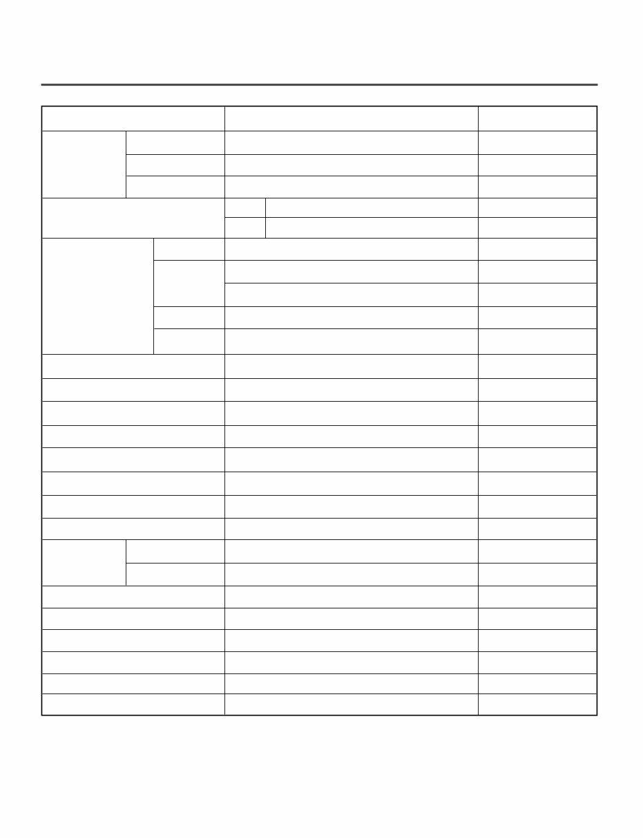
ITEM DLE2250* DLG2251* REMARK
Blue White
Powder coating
Color
Top Plate
Door Trim
ELECTRICITY
CONSUMPTION
MOTOR
HEATER
LAMP
GAS VALVE
CONTROL TYPE
DRUM CAPACITY
Weight (lbs) - Net/Gross
No. of Programs
No. of Dry Options
No. of Temperature Controls
Moisture
Temperature
No. of Dry Levels
Reversible Door
Drum
Child Lock
Interior Light
Product (WxHxD)
Sensor
POWER
SUPPLY
Material &
Finish
Silver color Spray
ELEC.
GAS
120/240V 60Hz (26A)/120/208V 60Hz (23A)
120V/60Hz (5A)
250W (4.5A)
5400W (22.5A)
4100W (21A)
15 W (0.2A)
13 W (0.11A) x 2
Electronic
7.1 cu.ft.
126 / 146
7
9
5
5
Available
Available
Available
Alcosta
Available
Available
27" x 42 3/4" x 28 1/3"
Packing (WxHxD) 29 1/2" x 44 3/4" x 30 3/4"
AC 240V (ELECTRIC MODEL)
AC 208V (ELECTRIC MODEL)
AC 120V
AC 120V (GAS MODEL)
Thermistor
Electrode sensor
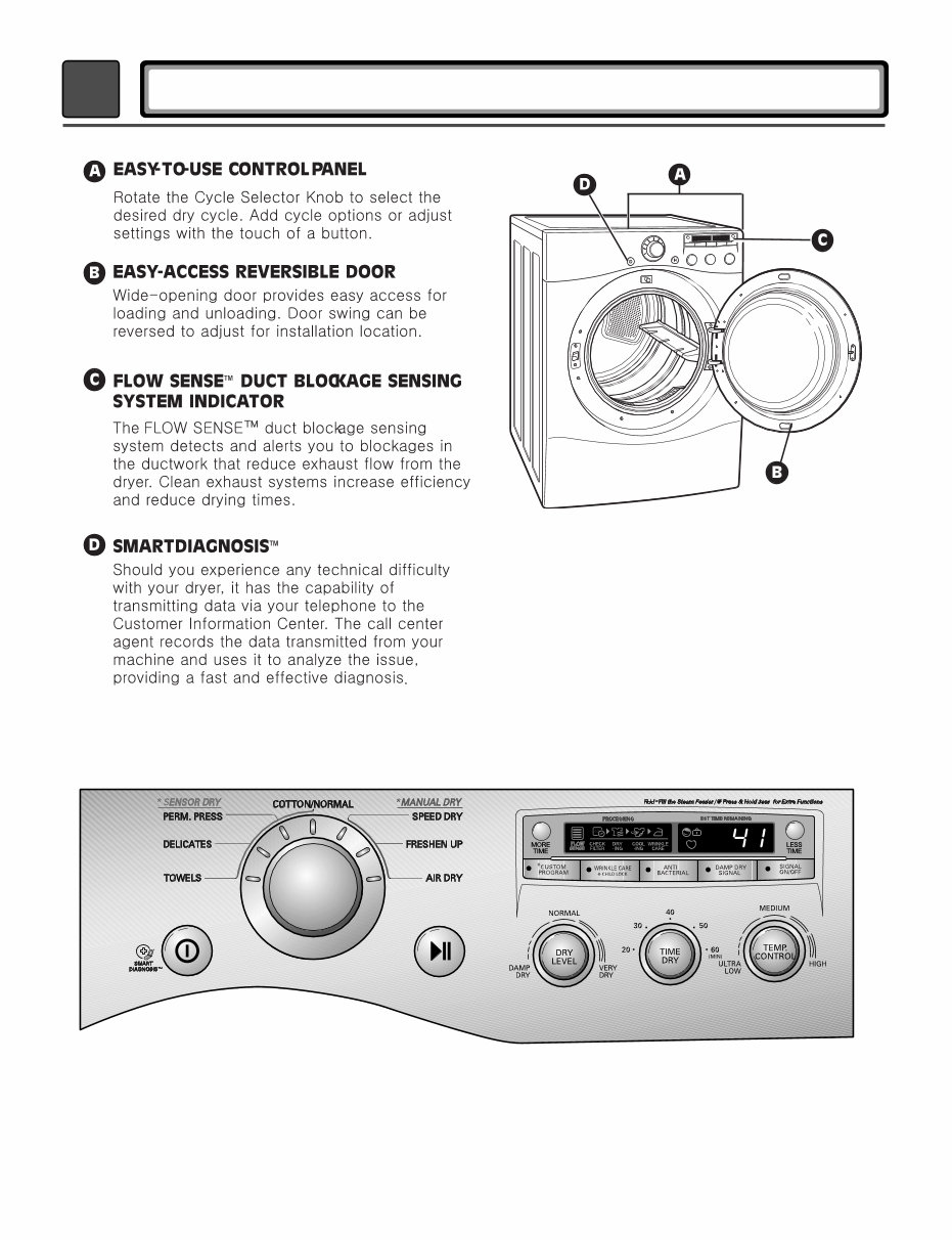
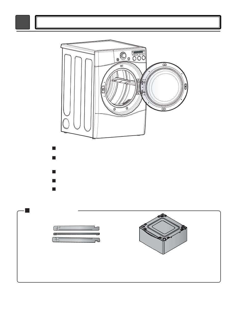
2 FEATURES AND BENEFITS
6
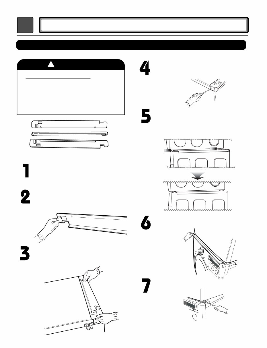
Peel the protective paper from the tape on
the side bracket.
7
3
INSTALLATION INSTRUCTIONS
Secure the side bracket to the washer with
a screw on the back of the bracket. Repeat
Steps 2, 3, and 4 for the other side.
Place the dryer on top of the washer by
placing the legs as shown. Be careful not to
pinch fingers between the washer and dryer.
Slide the dryer back against the stop on the
side rail.
Fit the side bracket firmly to the side of the
top plate by attaching the double-faced tape
to the top plate as picture shown.
Insert the front rail of the stacking kit. Push
the front rail back against the stops on the
side brackets.
• Do not use a stacking kit with a gas dryer in
potentially unstable conditions like a mobile
home.
Stacking Kit Installation Instructions
Place the washer firmly on a stable, even
and solid floor as product installation
instructions describe in the owner’s
manual.
Do not attempt this alone!
At least two people are required to lift and
position the dryer on top of a washing
machine!
Failure to heed this warning can result in
serious physical injury and damage to the
appliance.
WARNING
Stacking kit
Attach the front bracket to the side rails with
a screw on each side.
To ensure safe and secure installation, please observe the instructions below.
!
8
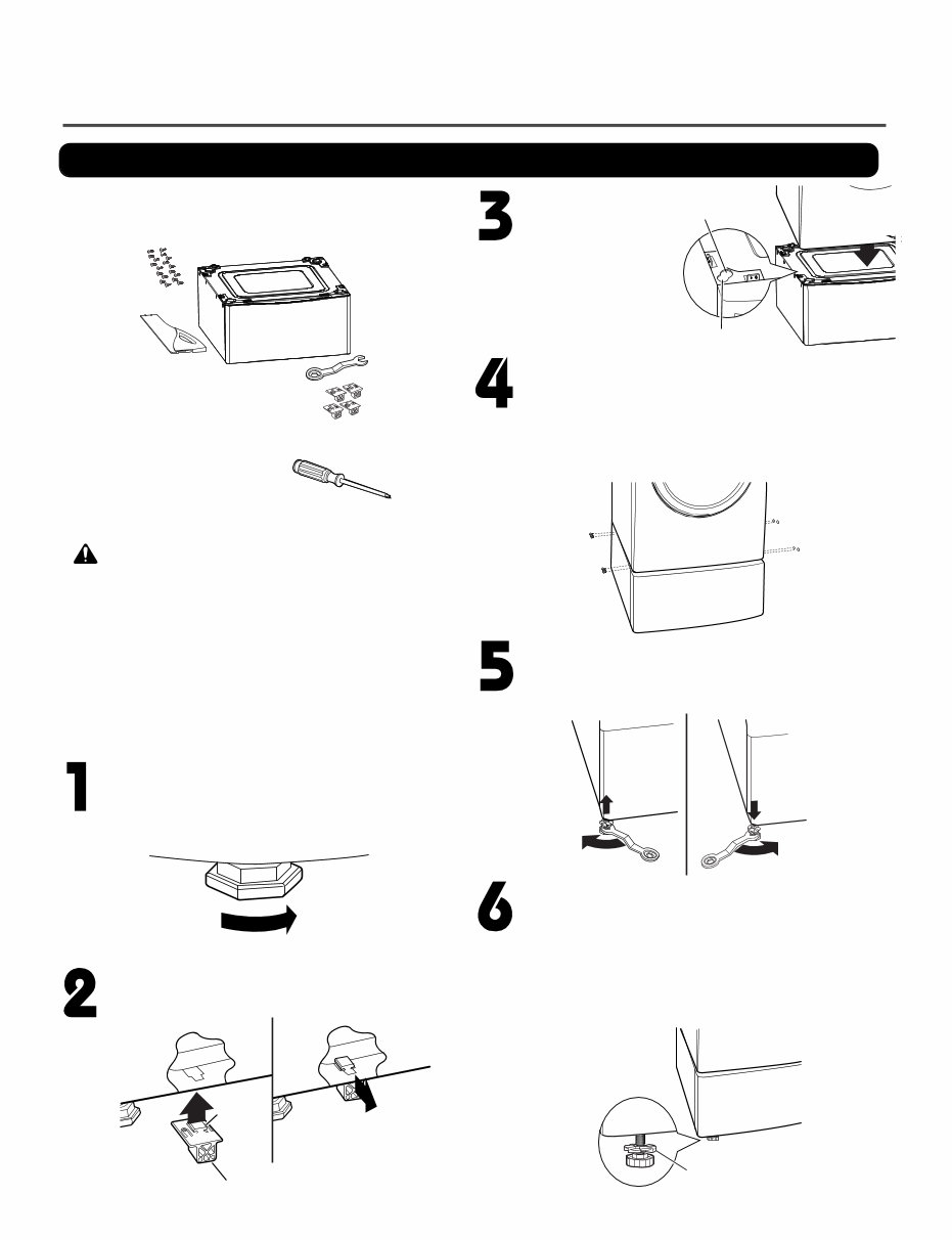
Pedestal Installation Instructions
The pedestal accessory includes:
•
Drawer divider (1)
•
Wrench (1)
•
Screws (18) †
•
T-clips (4) ††
Tools Needed for Installation:
•
Phillips-head screwdriver
•
Wrench (supplied)
† Dryer installation only uses 8 screws
†† For dryer only
To ensure safe and secure installation, please
thoroughly follow the instructions below.
• Incorrect installation can cause serious accidents.
• The appliances are heavy. Two or more people are
required when installing the pedestal. There is a
risk of serious back injury or other injuries.
• Do not allow children to play in or on the drawer.
There is a risk of suffocation or injury.
• Do not step on the handle. There is a risk of serious injury.
• If appliances are already installed, disconnect them
from all power, water, or gas lines and from draining or
venting connections. Failure to do so can result in
electrical shock, fire, explosion, or death.
• When installing, gloves must be put on.
WARNING
Retract fully
Retainer
T-clip
Make sure the leveling feet of the dryer are
fully retracted.
NOTE: The appliance and pedestal assembly
must be placed on a solid, sturdy, level floor
for proper operation.
Insert the T-clip of the 4 retainers into the dryer
base as shown. Press up on the back of the
clip and pull outward to lock into place.
Place the dryer on the
pedestal. Make sure
the front and back feet
are in the correct
positions. The dryer
feet will fit into the
innermost positions as
shown.
Make sure the screws on the pedestal align with the
holes in the retainers, then install 4 screws on each
side to securely attach the appliance to the pedestal.
NOTE: If the screws are not installed properly, noise
and vibration may result.
Move the appliance to the desired location.
Securely tighten all locknuts by hand.
NOTE: Noise and vibration may result if locknuts are not
tightened.
Be sure to connect the appliances to all water, power,
or gas lines and draining or venting connections before
operation.
If there is excessive vibration during the first operation
after installation, slightly adjust the leveling feet.
Loosen the locknuts on all 4 leveling feet of the
pedestal until you can turn them with the wrench.
Turn clockwise to raise or counterclockwise to lower
until the pedestal is level and all 4 feet are solidly
against the floor.
For dryer
For washer/combo
Raise
Lower
Locknut
9
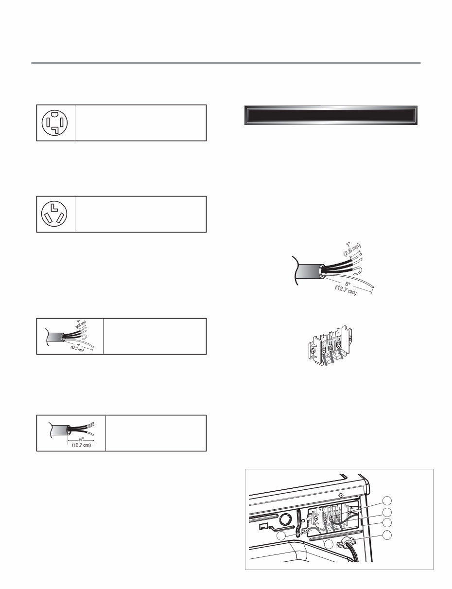
Use the instructions under option 2 or 3 if your
home has a 3-wire receptacle (NEMA type 10-30R).
Use option 2 if local codes and ordinances permit
the connection of a chassis ground to the neutral
connector. If this is not permitted, use option 3.
Review the following options to determine the appropriate electrical connection for your home:
Electric Dryer Only
If this type is available at your home. you will be
connecting to a fused disconnect or circuit breaker
box
Important : Grounding through the neutral conductor
is prohibited for (1) new branch-circuit installations,
(2) mobile homes, and (3) recreational vehicles, and
(4) areas where local codes prohibit grounding through
the neutral conductor.
Prepare minimum 5ft(1.52m) of length in order for
dryer to be replaced.
First, peel 5 inch (12.7cm) of covering material from
end. Make a 5 inch of ground wire bared. After cutting
1
1
/2 inch (3.8cm) from 3 other wires. peel insulation
back 1inch (2.5cm). Make ends of 3 wires a hook
shape.
Then, put the hooked shape end of the wire under the
screw of the terminal block(hooked end facing rightward)
and pinch the hook together and screw tightly.
Use the instructions under option 1 if your home
homehas a 4-wire receptacle (NEMA type 14-30R).
If this type is available at your home. you will be
connecting to a fused disconnect or circuit breaker
box
1. Connect neutral wire(white) of power cord to center
terminal block screw.
2. Connect red and black wire to the left and right
terminal block screws.
3. Connect ground wire(green) of power cord to external
ground screw and move neutral ground wire of
appliance and connect it to center screw.
4. Make sure that the strain relief screw is tightened.
and be sure that all terminal block nuts are on tight and
power cord is in right position.
1 "
(2.5 cm)
5 "
(12.7 cm)
3-wire direct
4-wire receptacle
(NEMA type14-30R)
3-wire receptacle
(NEMA type10-30R)
4-wire direct
5"
(12.7 cm)
4-wire connection : Direct wire
1"
(2.5 cm)
5 "
(12.7 cm)
F
a
b
E
D
C
10
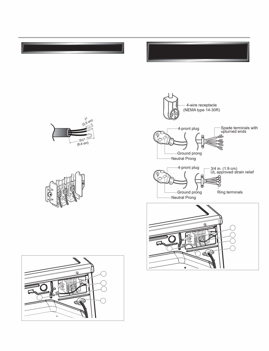
Important : Grounding through the neutral conductor
is prohibited for (1) new branch-circuit installations,
(2) mobile homes, and (3) recreational vehicles, and
(4) areas where local codes prohibit grounding through
the neutral conductor.
Prepare minimum 5ft(1.52m) of length in order for
dryer to be replaced.
First, peel 3
1
/2 inch (8.9cm) of covering material
from end and bare 1 inch from the ends.
1. Connect neutral wire(white) of power cord to
center terminal block screw.
2. Connect red and black wire to the left and right
terminal block screws.
3. Make sure that the strain relief screw is tightened
and be sure that all terminal block nuts are on
tight and power cord is in right position.
Then, put the hooked shape end of the wire under
the screw of the terminal block(hooked end facing
rightward) and pinch the hook together and screw
tightly.
1 "
( 2 . 5 c m )
3V 2 "
(8.9 cm)
3-wire connection : Direct wire
1. Connect the neutral wire (white) of the power
cord to the center terminal block screw.
2. Connect the red and black wires to the left and
right terminal block screws.
3. Connect the ground wire (green) of the power
cord to the external ground screw. Remove the
neutral ground wire of appliance and connect it to
center screw.
4. Make sure that the strain relief screw is tightened
and that all terminal block nuts are tight and the
power cord is in the right position.
F
a
b
E
D
C
• lf your local codes or ordinances do not allow the
use of a 3 wire connection, or you are installing
your dryer in a mobile home, you must use a
4-wire connection.
Option 1: 4-wire connection with
a Power supply cord.
E
a
D
B
C
You're Reading a Preview
What's Included?
Fast Download Speeds
Online & Offline Access
Access PDF Contents & Bookmarks
Full Search Facility
Print one or all pages of your manual
$35.99
Viewed 92 Times Today


Secure transaction
What's Included?
Fast Download Speeds
Online & Offline Access
Access PDF Contents & Bookmarks
Full Search Facility
Print one or all pages of your manual
$35.99
This service and repair manual is an essential resource for both professional mechanics and DIY enthusiasts. It provides comprehensive information for troubleshooting and repairing the LG DLE3050W ultra-large capacity dryer.
- Specifications
- Features and Benefits
- Installation Instructions
- Dryer Cycle Process
- Component Testing Information
- Wiring Diagram
- Troubleshooting
- Diagnostic Test
- Disassembly Instructions
- Exploded View
This detailed manual is illustrated with pictures and step-by-step instructions, providing guidance on servicing and repairing the device effectively. It is the official and complete service and repair manual, ensuring high-quality resolution for printed pages.
Upon payment, you will have instant access to the manual, eliminating the need for shipping and allowing you to commence repairs within minutes.
Language: English
Format: PDF
Pages: 45


