


CAUTION
- BEFORE SERVICING THE UNIT,
READ THE SAFETY PRECAUTIONS IN THIS MANUAL.
- ONLY FOR AUTHORIZED SERVICE.
Website:http://www.lgservice.com
Dehumidifier
SERVICE MANUAL
MODEL: LD301EL
Internal Use Only

—2—
1. PREFACE
1.1 SAFETY PRECAUTIONS ...........................................................................................................................3
1.2 FEATURES AND DIMENSIONS ................................................................................................................3
1.2.1 FEATURES........................................................................................................................................3
1.2.2 DIMENSIONS ....................................................................................................................................3
1.3 SPECIFICATIONS ......................................................................................................................................4
1.4 CONTROL TYPE ........................................................................................................................................5
1.4.1 ELECTRONIC TYPE .........................................................................................................................5
1.5 HOW TO OPERATE DEHUMIDIFIER ........................................................................................................6
1.5.1 HOW DOES THE DEHUMIDIFIER WORK? .....................................................................................6
1.5.2 LOCATION FOR THE DEHUMIDIFIER.............................................................................................6
1.5.3 AUTO DEFROST...............................................................................................................................6
1.5.4 HUMIDITY CONTROLLER ................................................................................................................7
2. CIRCUIT DIAGRAM............................................................................................................................8
3. DISASSEMBLY INSTRUCTIONS
3.1 MECHANICAL PARTS .............................................................................................................................9
3.1.1 BUCKET AND AIR FILTER .............................................................................................................9
3.1.2 HOSE COVER AND REAR GRILLE................................................................................................9
3.1.3 CONTROL BOX COVER AND FRONT GRILLE..............................................................................9
3.2 CONTROL PARTS ..................................................................................................................................10
3.2.2 POWER CORD ASSEMBLY ...........................................................................................................10
3.2.8 SHROUD AND MOTOR...................................................................................................................12
3.2.3 PWB(PCB) ASSEMBLY, MAIN .......................................................................................................10
3.2.1 CAPACITOR ....................................................................................................................................10
3.2.5 MICRO SWITCH ASSEMBLY .........................................................................................................10
3.2.6 CONTROL PANEL ..........................................................................................................................11
3.2.7 FAN..................................................................................................................................................12
3.2.9 DRAIN PAN .....................................................................................................................................12
3.3 REFRIGERATING CYCLE .......................................................................................................................13
3.3.1 CONDENSER, EVAPORATOR AND CAPILLARY TUBE ...............................................................13
3.3.2 ROTARY COMPRESSOR ..............................................................................................................13
3.4 HOW TO REPLACE REFRIGERATION SYSTEM ...................................................................................14
4. TROUBLESHOOTING GUIDE ...................................................................................................16
5. EXPLODED VIEWS ..........................................................................................................................18
CONTENTS
3.2.4 CONTROL BOX...............................................................................................................................10
—3—
1. PREFACE
This Service Manual provides various service information, including the mechanical and electrical parts.
This dehumidifier was manufactured and assembled under the strict quality control procedures.
The refrigerant is charged at the factory. Be sure to read the safety precaution prior to servicing the unit.
1.1 SAFETY PRECAUTIONS
• Disconnect the power supply before servicing or replacing any component.
• Do not cut off the grounding prong or alter the plug in any manner.
1.2 FEATURES AND DIMENSIONS
1.2.1 FEATURES
• Quiet operation
• High efficiency
• Adjustable humidistat
• Automatic defrost
• Automatic shut-off
• Bucket-full indicator light
• Easy roll casters
• Removable bucket.
• Washable air filter
• Two-speed fan
• Drain hose connection.
• Low temperature operation
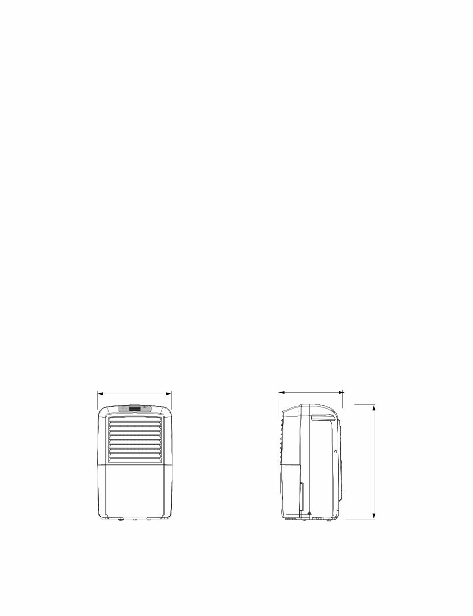
1.2.2 DIMENSIONS (mm)
Figure 1
265
540
343
—4—
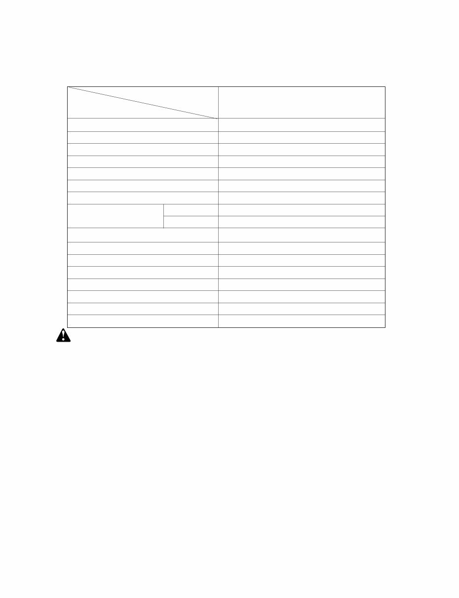
1.3 SPECIFICATIONS
*NOTE: Specifications are subject to minor change without notice for further improvement.
CAPACITY(Pints/24hrs)
30
POWER SUPPLY(Phase,V,Hz)
1Ø, 115V,60Hz
INPUT(W) 420
RUNNING CURRENT(A)
4.0
ENERGY FACTOR(L/kw.h)
1.40
REFRIGERANT
REFRIGERANT CHARGE, oz(g)
4.23(120)
THERMISTOR OPEN 28.4˚F
CLOSE 41˚F
COMPRESSOR MODEL No. GS040CAA
PROTECTOR OVERLOAD PROTECTOR FOR COMPRESSOR
INTERNAL PROTECTOR(FUSE)
CAPACITOR
MOTOR ASSEMBLY,SINGLE
SWITCH ASSEMBLY,MICRO 15A/250VAC
OUTSIDED MENSIONS WxHxD,mm(in) 343X540X265(13 1/2 x 21 1/4 x 10 3/7)
NET WEIGHT,kg(lbs) 14.1(31.1)
MODELS
ITEM LD301EL
45μF,270VAC
Conductivity motor,37W/0.36A,Thermal cutoff:266 °FV/130°C
R410A
R410A Model Refrigerant Pressure 1.6 times higher than the R22 Model.
After vacuum, charge Refrigerant is completed within 3 minutes.
Refrigerant cycle should be sealed quickly after charging to avoid leakage.
Refrigerant R410A charging equipment should be separated with other Refrigerants.
Refrigerant stored in low temperatures condition, below 10°C
—5—
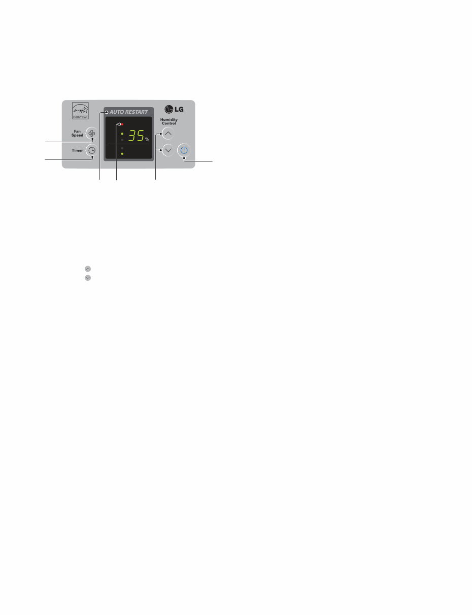
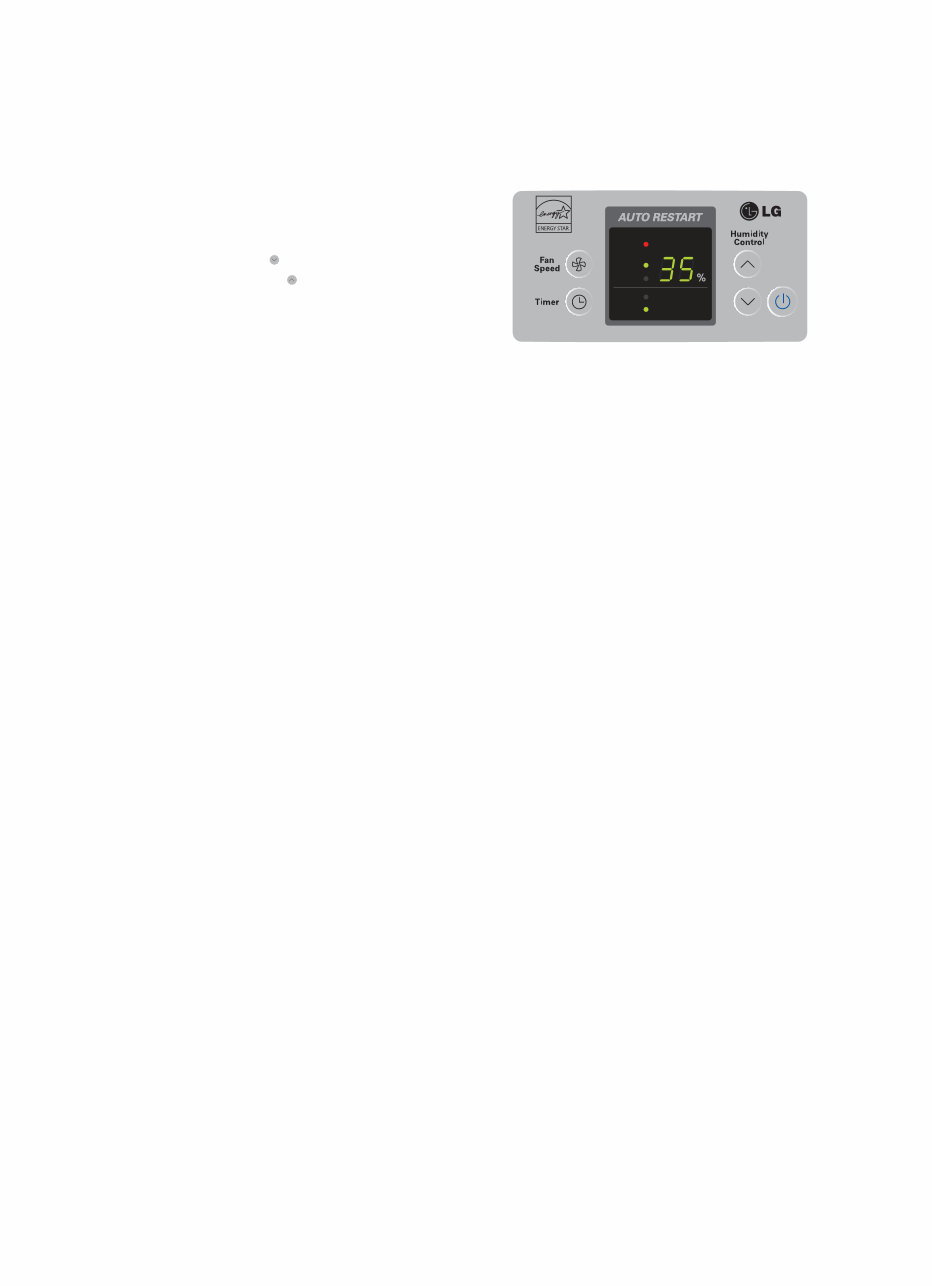
5. Bucket Full Indicator
• This light glows when the water bucket is full and needs
to be emptied.
1. Power
• Operation starts when this button is pressed and stops
when the button is pressed again.
3.Fan Speed
• This controls the speed of the airflow.
• High: Fan speed is set to high.
• Low: Fan speed is set to low.
• When Fan Speed button is pressed, the fan speed
mode is changed.
4.Timer
• Press this button to select type of operation.
• Select continuous On for uninterrupted operation.
• Select either 2 or 4 hr. On/Off for cycled operation:
The unit will operate for 2 or 4 hours, and then shut
off completely for 2 or 4 hours.
The cycle repeats until you change the setting.
• When Timer button is pressed, the Timer indicator
lights shift as follow from 2hr.On/Off to 4hr.On/Off.
6. Auto Restart
• Once power is restored after a power outage, the unit
returns to its previous operation setting after a 2 minute
delay.
The fan runs immediately when the power is restored.
2. Humidity Control
• This button controls the humidity in the room.
• Press button to raise the humidity setting.
• Press button to lower the humidity setting.
• The humidity setting can be set to a permanent "On"
setting or to a specific humidity setting between 35% and
70% in 5% increments.
• "On" setting: Dehumidifier runs continuously regardless
of humidity condition.
• 35% - 70% setting: Dehumidifier runs on and off
according to surrounding humidity conditions.
Figure 3
1.4 CONTROL TYPE
1.4.1 Electronic type
Bucket Full
2 hr. on/off
4 hr. on/off
High
Low
6 5
3
4 1
2
—6—
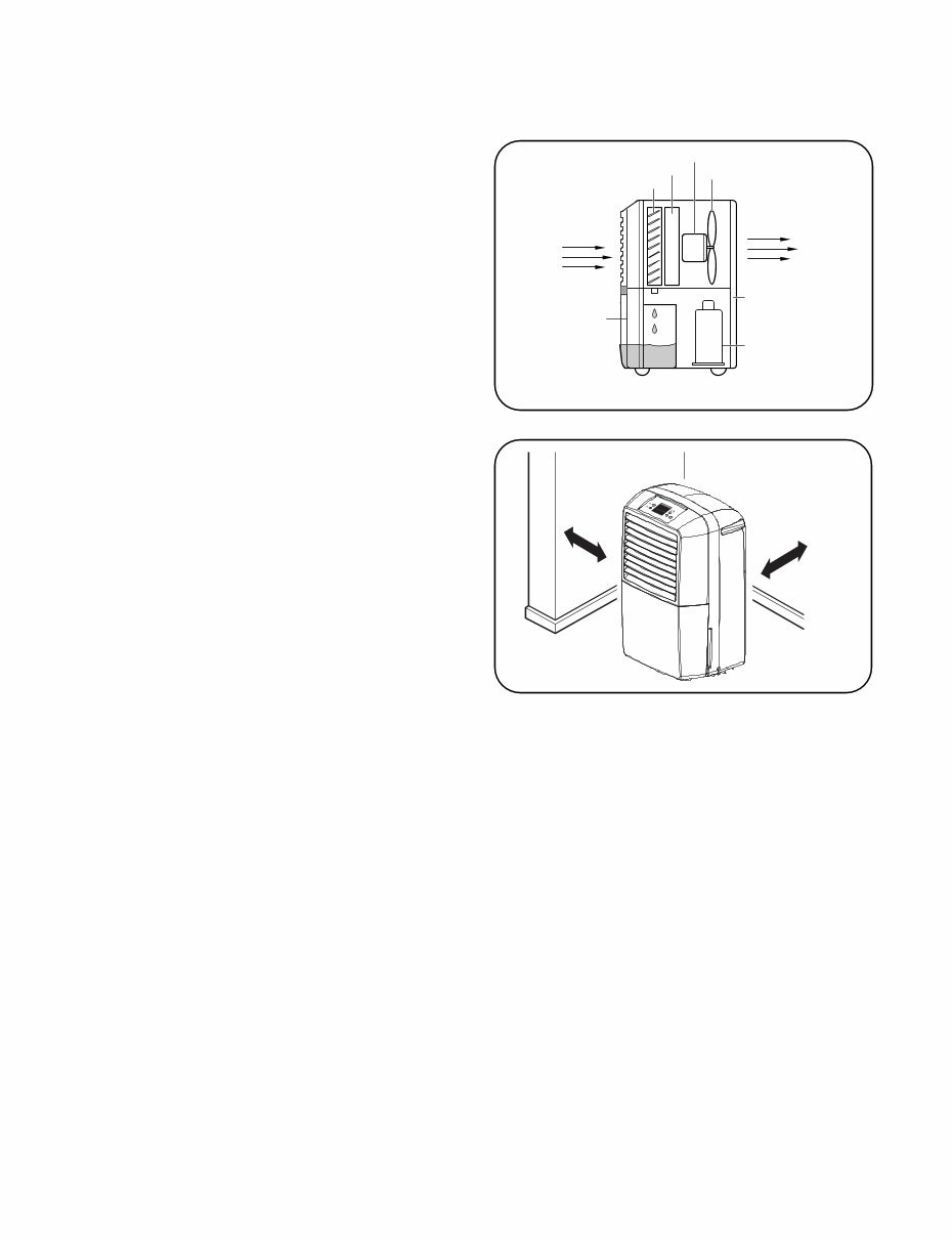
1.5.1 HOW DOES THE DEHUMIDIFIER WORK?
Moist, humid air is drawn over a cold refrigerated
dehumidifying coil. Moisture in the air condenses on this
coil and drains into a bucket (or through the bucket into a
hose and drain).
Dry, clean air is drawn over the condenser where it is
actually heated several degrees and discharged out the
rear grill into the room. (See Figure 4)
■It is normal for the surrounding air to become
slightly warmer as the dehumidifier operates.
This warming effect further reduces the relative humidity
of the surrounding air.
1.5.2 LOCATION FOR THE DEHUMIDIFIER
Allow at least 12 inches of space on all sides of the
unit for good air circulation. (See Figure 5)
■The dehumidifier must be operated in an enclosed
area to be most effective.
■Close all doors, windows and other outside
openings to the room.
Place the dehumidifier in a location that does not
restrict air flow into the front grille or out the rear grille.
The operation of dehumidifier in a basement will have
little or no effect in drying an adjacent enclosed
storage area, such as a closet, unless there is
adequate circulation of air in and out of the area.
1.5 HOW TO OPERATE DEHUMIDIFIER
1.5.3 AUTO DEFROST
When frost builds up on the cooling coils, the unit will automatically cycle off until the frost disappears. The fan continues to run.
NOTE: The unit will not operate satisfactorily if the room temperature is below 65˚F(18˚C). If the dehumidifier is
operated in low temperature conditions frost can form in the evaporator coil and the unit will cycle ON/OFF
repeatedly. In this case, please check your room temperature conditions and stop the unit.
NOTE: The low temperature operation feature in the LD301EL model will continuously cycle up to a temperature of 42°F(6°C) .
Fan
Side View
Condenser
Evaporator
Motor
Compressor
Rear Grille
Bucket
Dry
Air Out
Humid
Air In
12"
12"
Figure 4
Figure 5
—7—
1.5.4 HUMIDITY CONTROLLER
1.5.4Electronic Type
The humidity control can be set 'on' or 35%-70%
RH(Relative Humidity) for normal operation. (See Figure 7)
If you need drier air, press the Humidity Control button.
If you need moister air, press the Humidity Control
button.
Press the Power button to stop the unit manually.
Figure 7
Bucket Full
2 hr. on/off
4 hr. on/off
High
Low
—8 —
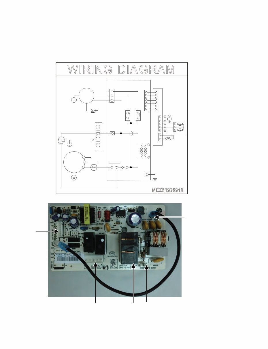
• MODEL : LD301EL
CN-DISP
RY-COMP CN-MOTOR
CN-N
ETH
2. CIRCUIT DIA GRAM
WIRING DIAGRAM
MEZ61926910
MAIN PCB
CN-MOTOR
CN-AC1
RY-COMP
O L - Y R
I H - Y R
FUSE 250V T3.15A
POWER
SMPS
P S I D - N C
HUMIDITY
SENSOR
THERMISTOR
BUCKET
S/W
4 3
BR
BL
RD
WH(BL) (N)
BK(BR) (L)
L B
BK(HI)
RD(LOW)
OR(COM)
MOTOR
R
C
S
O.L.P
COMP.
GN/YL
GN/YL
R O T I C A P A C
C
H
YL
F
YL
GN/YL
DISPLAY P.C.B
BK
ETH
3.1 MECHANICAL PARTS
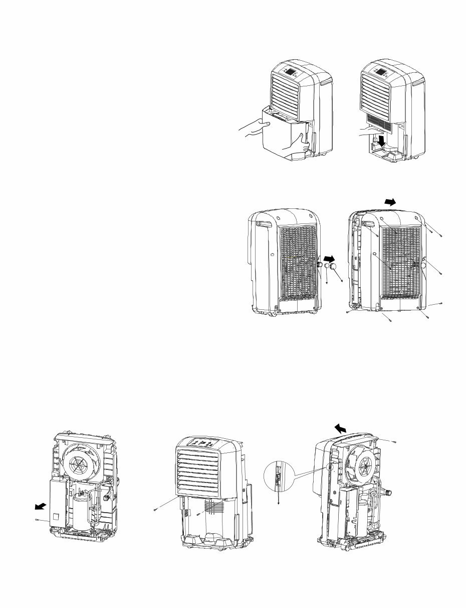
3.1.1 BUCKET AND AIR FILTER
1. Press the power button off.
2. Disconnect the power supply.
3. Remove the bucket. (See Figure 9)
4. Pull out the air filter.
(See Figure 10)
3.1.2 HOSE COVER AND REAR GRILLE
2. Remove 10 screws which fasten the rear grille.
3. Pull the rear grille backward .(See Figure 12)
3.1.3. CONTROL BOX COVER AND FRONT GRILLE
1. Remove the Rear Grille according to the procedure above.
2. Remove 2 screws that fasten Control box cover.
(See Figure 13)
3. Remove cover on Control box.
—9—
3. DISASSEMBLY INSTRUCTIONS
Figure 9 Figure 10
Figure 11 Figure 12
1. Remove the hose cover and hose cap.
(See Figure 11)
Figure 13
4. Remove 4 screws that secure the front grille.
6. Remove two hooks out of shroud and then pull the front grille forward.
(See Figure 14-1,14-2)
Figure 14-1 Figure 14-2
5. Disconnect the leads between diplay PCB and other parts.
Cap
Cover
hook
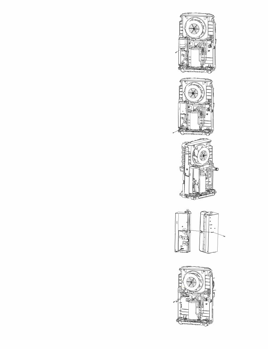
3.2 CONTROL PARTS
3.2.2 POWER CORD ASSEMBLY
1. After remove the cover and the capacitor, remove the screw
that holds the ground wire in power cord Assy.
2. Disconnect the remaining leads of the power cord
from the PWB(PCB) ASSEMBLY, MAIN, then
remove it from the control box.(See Figure 16)
3.2.4 PWB(PCB) ASSEMBLY, MAIN
1.Disconnect all leads of the motor and the compressor
from PWB(PCB) ASSEMBLY, MAIN.
1. Remove the screw which fastens the PWB(PCB)
ASSEMBLY, MAIN and pull it out after unhooking
from 2 rectangular holes of the control box (lower).
(See Figure 18)
3.2.5 MICRO SWITCH ASSEMBLY
1. After remove the control box according to the
the procedure above.
—10—
Figure 17
Figure 16
Figure 19
Figure 15
3.2.1 CAPACITOR
1. Remove the screw that fastens the capacitor.
(See Figure 15)
3.2.3 CONTROL BOX
Figure 18
2. Remove two screws which fasten the control box
and then pull the control box out of the product.
(See Figure 17)
Power cord bushing
screw
2. Remove the screws and pull out the micro
switch from the drain pan. (See Figure 19)
2. Remove capacitor from the control box and then
disconnect all leads from it.
You're Reading a Preview
What's Included?
 Lifetime Access
Fast Download Speeds
Online & Offline Access
Access PDF Contents & Bookmarks
Full Search Facility
Print one or all pages of your manual
$28.99
LG LD301EL Dehumidifier Service Manual
Viewed 11 Times Today

What's Included?
Lifetime Access
Fast Download Speeds
Online & Offline Access
Access PDF Contents & Bookmarks
Full Search Facility
Print one or all pages of your manual
$28.99

Secure transaction
What's Included?
Lifetime Access
Fast Download Speeds
Online & Offline Access
Access PDF Contents & Bookmarks
Full Search Facility
Print one or all pages of your manual
Description
The LG LD301EL Dehumidifier Service Manual is an essential resource for both professional mechanics and DIY enthusiasts. This manual provides comprehensive information in English and spans 19 pages. It includes circuit diagrams, disassembly instructions, troubleshooting guides, and exploded views, making it an invaluable tool for servicing the LG LD301EL dehumidifier.
Whether you are using Windows or MAC, this manual is available in a format that is easy to access and utilize for all your repair needs.


